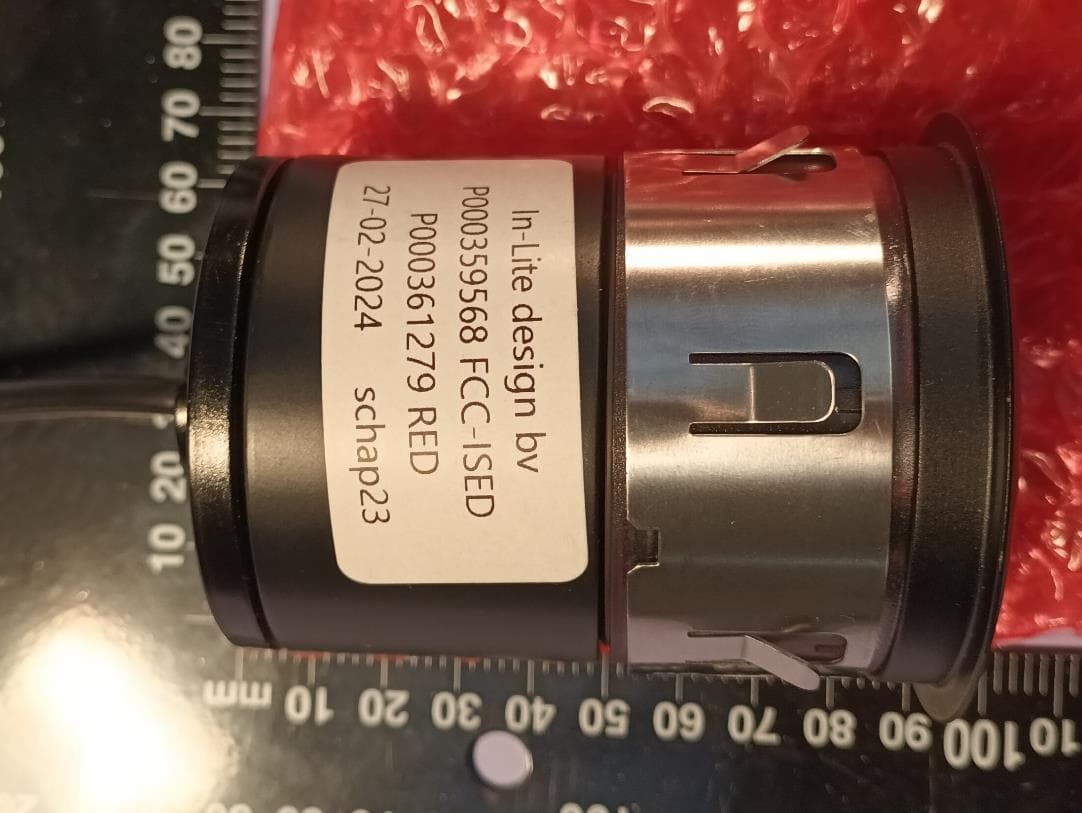
2AU26-SMARTMOVEMotion sensor G3
in-lite
Click to zoom
Application Details
- Equipment Class
- DTS - Digital Transmission System
- Date of Grant
- Apr 01, 2020
- Application Purpose
- Original Equipment
- Date of Application
- Mar 31, 2020
- Equipment Note
- Motion sensor G3
- Frequency Range
- 2402.00000000 - 2480.00000000
- Company
- in-lite
- Country
- Netherlands
Documents & Files
Document Text
Text extracted from the exhibit documents filed with the FCC. Open a document above to read the original.
Users Manual
in-lite INSTALLATION MANUAL SMART HUB-150 www.in-lite.com 03-09-2019 INSTALLATION MANUAL SMART HUB-150 12 V SMART MOVE Attention This product may only be used within the in-lite system. If components are used in the system that do not originate from in-lite, the warranty no longer applies. Install the in- lite system components (fixtures, transformers, mini-connectors, Easy-Locks and cable connectors) so that they can easily be replaced Never use the in-lite low-voltage cable directly connected to 100-230V. This cable is only meant for use with the components of the in-lite 12 Volt (low- voltage) system. in-lite INSTALLATION MANUAL SMART HUB-150 www.in-lite.com 03-09-2019 Contents 1x SMART HUB-150 INPUT : 230 V~, 50 Hz OUTPUT HUB-150: 12 V~, 12.5 A max., 150 VA Or, 1x SMART HUB-150 INPUT : 120 V~, 60 Hz OUTPUT HUB-150: 12 V~, 12.5 A max., 150 VA Dimensions 22 8 x 143 x 82 mm / 9.0 x 5.6 x 3.2 inches 2x screws Optional 1x SMART MOVE (motion sensor) Frequency : 2400-2480 MHz Modulation type : GF SK/DPSK Please read the following instructions before installing. You are advised to keep these installation instructions in a safe place. Although a 12 V system is safe, we advise you to have a qualified electrician check the installation. Use The SMART HUB-150 transformer is controlled by the in-lite app, suitable for Android and iOS phones or tablets produced, for example, by Samsung and Apple. The transformer is fitted with an integrated timer and an astronomical clock. You can make use of various options whereby the lamps are activated during the hours of darkness or for a certain time period you can set yourself. You can also manually switch the lamps ON and OFF at any time. Bluetooth Low Energy The transformer connects to the phone or tablet using Bluetooth Low Energy. BLE is a new low-energy form of Bluetooth and is more user-friendly and more secure than, for instance Wi-Fi. Three power lines A total of 150 VA in fixtures can be connected to the SMART HUB-150. Three power cables can easily be connected to the transformer using the Easy-Connect click connectors. With one transformer you’re able to create three lighting zones in your outdoor space. It’s not necessary to evenly divide the maxiumum of 150 VA among the three lines. It’s also possible to use only 1 or 2 of the 3 power lines. in-lite INSTALLATION MANUAL SMART HUB-150 www.in-lite.com 03-09-2019 Safety The external flexible cord of this product cannot be replaced; if the cord is damaged, the product shall be scrapped. When the transformer is connected in a wrong way (short circuit) or it encounters an overload, the “Off-led” will blink to signal the installer. Above a certain level of overload the transformer will shut down and reset itself. This procedure will loop until the connection has be done right or the load is reduced to an acceptable level. This product has triple protection. It’s based on 3 mechanisms: 1. Current monitoring by software, 2. Voltage monitoring after PTC’s (3x 9A PTC), 3. Transformer temperature monitoring (thermal resettable fuse inside toroid transformer). The software protection is based on one true-RMS current measurement and two voltage measurements. If the external load is increased, the following levels are reached for SMART HUB-150: • Detection levels calibrated for each product at 100% of nominal load (150 VA). • If the current exceeds 120% for a few seconds (>180VA), the “off- Led” (around the on/off-button) starts blinking slowly until the load is decreased below 120%. • If the current exceeds 140% for a few seconds (>210VA), the relay is switched off and the “off- Led” starts blinking fast until the on/off-button is activated (reset after overload). • If the current exceeds 200% (>300VA), the relay is switched-off immediately until the on/off-button is activated (reset after short-circuit). • If the customer resets too many times during overload/short-circuit the 3 PTCs on the connection PCB become hot and the output voltage will become too low, which is measured by the software. The output will be disabled for 1 minute to allow cooling down. • Finally, if all of the above protections fail the temperature sensing switch inside the transformer will break the input current if its temperature rise is too high. This mechanism resets automatically after cooling down. The control of the relay is synchronized with the mains input, it switches on and off during the zero crossing off the current to prevent induction voltages (spikes). If the supply voltage for the control part becomes too low (long power dips) the output will be disabled. After restoring of the mains supply the product will start again in the last known mode. in-lite INSTALLATION MANUAL SMART HUB-150 www.in-lite.com 03-09-2019 IC Statement This device complies with Industry Canada licence-exempt RSS standard(s). Operation is subject to the following two conditions: 1) this device may not cause interference and 2) this device must accept any interference, including interference that may cause undesired operation of the device Le présent appareil est conforme aux CNR d'Industrie Canada applicables aux appareils radio exempts de licence. L'exploitation est autorisée aux deux conditions suivantes : (1) l'appareil ne doit pas produire de brouillage, et (2) l'utilisateur de l'appareil doit accepter tout brouillage radioélectrique subi, même si le brouillage est susceptible d'en compromettre le fonctionnement. FCC Statement This equipment has been tested and found to comply with the limits for a Class C digital device, pursuant to Part 15 of the FCC Rules. These limits are designed to provide reasonable protection against harmful interference in a residential installation. This equipment generates, uses and can radiate radio frequency energy and, if not installed and used in accordance with the instructions, may cause harmful interference to radio communications. However, there is no guarantee that interference will not occur in a particular in…
Text truncated - open the document above for the full version.
Users Manual
in-lite INSTALLATION MANUAL SMART HUB-150 www.in-lite.com 03-09-2019 INSTALLATION MANUAL SMART HUB-150 12 V Attention This product may only be used within the in-lite system. If components are used in the system that do not originate from in-lite, the warranty no longer applies. Install the in- lite system components (fixtures, transformers, mini-connectors, Easy-Locks and cable connectors) so that they can easily be replaced Never use the in-lite low-voltage cable directly connected to 100-230V. This cable is only meant for use with the components of the in-lite 12 Volt (low- voltage) system. in-lite INSTALLATION MANUAL SMART HUB-150 www.in-lite.com 03-09-2019 Contents 1x SMART HUB-150 INPUT : 230 V~, 50 Hz OUTPUT HUB-150: 12 V~, 12.5 A max., 150 VA Or, 1x SMART HUB-150 INPUT : 120 V~, 60 Hz OUTPUT HUB-150: 12 V~, 12.5 A max., 150 VA Dimensions 22 8 x 143 x 82 mm / 9.0 x 5.6 x 3.2 inches 2x screws Optional SMART MOVE (motion sensor) Please read the following instructions before installing. You are advised to keep these installation instructions in a safe place. Although a 12 V system is safe, we advise you to have a qualified electrician check the installation. Use The SMART HUB-150 transformer is controlled by the in-lite app, suitable for Android and iOS phones or tablets produced, for example, by Samsung and Apple. The transformer is fitted with an integrated timer and an astronomical clock. You can make use of various options whereby the lamps are activated during the hours of darkness or for a certain time period you can set yourself. You can also manually switch the lamps ON and OFF at any time. Bluetooth Low Energy The transformer connects to the phone or tablet using Bluetooth Low Energy. BLE is a new low-energy form of Bluetooth and is more user-friendly and more secure than, for instance Wi-Fi. Three power lines A total of 150 VA in fixtures can be connected to the SMART HUB-150. Three power cables can easily be connected to the transformer using the Easy-Connect click connectors. With one transformer you’re able to create three lighting zones in your outdoor space. It’s not necessary to evenly divide the maxiumum of 150 VA among the three lines. It’s also possible to use only 1 or 2 of the 3 power lines. in-lite INSTALLATION MANUAL SMART HUB-150 www.in-lite.com 03-09-2019 Safety The external flexible cord of this product cannot be replaced; if the cord is damaged, the product shall be scrapped. When the transformer is connected in a wrong way (short circuit) or it encounters an overload, the “Off-led” will blink to signal the installer. Above a certain level of overload the transformer will shut down and reset itself when the touch pad is activated manually. This procedure will loop until the connection has be done right or the load is reduced to an acceptable level. This product has triple protection. It’s based on 3 mechanisms: 1. Current monitoring by software, 2. Voltage monitoring after PTC’s (3x 9A PTC), 3. Transformer temperature monitoring (thermal resettable fuse inside toroid transformer). The software protection is based on one true-RMS current measurement and two voltage measurements. If the external load is increased, the following levels are reached for SMART HUB-150: • Detection levels calibrated for each product at 100% of nominal load (150 VA). • If the current exceeds 120% for a few seconds (>180VA), the “off- Led” (around the on/off-button) starts blinking slowly until the load is decreased below 120%. • If the current exceeds 140% for a few seconds (>210VA), the relay is switched off and the “off- Led” starts blinking fast until the on/off-button is activated (reset after overload). • If the current exceeds 200% (>300VA), the relay is switched-off immediately until the on/off-button is activated (reset after short-circuit). • If the customer resets too many times during overload/short-circuit the 3 PTCs on the connection PCB become hot and the output voltage will become too low, which is measured by the software. The output will be disabled for 1 minute to allow cooling down. • Finally, if all of the above protections fail the temperature sensing switch inside the transformer will break the input current if its temperature rise is too high. This mechanism resets automatically after cooling down. The control of the relay is synchronized with the mains input, it switches on and off during the zero crossing off the current to prevent induction voltages (spikes). If the supply voltage for the control part becomes too low (long power dips) the output will be disabled. After restoring of the mains supply the product will start again in the last known mode. in-lite INSTALLATION MANUAL SMART HUB-150 www.in-lite.com 03-09-2019 Installation The SMART HUB-150 is easy to install. After mounting the transformer and downloading and installing the in- lite application (app), the system is ready for connection. All lights can be controlled with the in-lite app on a smart phone or tablet. The app, which is suitable for an Android and iOS device, can be downloaded from the app store and installed on your device. The in-lite app makes it possible to communicate with the transformer by a Bluetooth connection. The app automatically recognizes which lines are in use. In the app you can turn light sections (total 3) “ON” and “OFF”. You can also set different scenarios based on sunset and sunrise, time of the day and/or movement detection (with accessory SMART MOVE). It’s possible to share the in-lite app with other people like familiy members. The Share function makes it possible to quickly link an extra device. The settings are duplicated so there’s no need to set again for the linked device. in-lite INSTALLATION MANUAL SMART HUB-150 www.in-lite.com 03-09-2019 Installation step by step Although the transformer is designed to withstand inclement weather, you are recommended not to place it close to a sprayer system. Place the transformer at least 50 cm above the ground and in th…
Text truncated - open the document above for the full version.
External Photos
External Photo Module Product name FCC ID : SMART MOVE : 2AU26-SMARTMOVE ISED ID : 25679-SMARTMOVE 190800657 Ver 1.00 190800657 Ver 1.00 Table of Contents 1 External Photos ....................................................................................................................................... 3 1.1 Front View ............................................................................................................................................. 3 1.2 Back view ............................................................................................................................................... 3 190800657 Ver 1.00 1 External Photos 1.1 Front View 1.2 Back view
ID Label/Location Info
Label location G3 transformer (SMART HUB-150) + G3 motion sensor (SMART MOVE)
Internal Photos
Internal Photo Module Product name FCC ID : SMART MOVE : 2AU26-SMARTMOVE ISED ID : 25679-SMARTMOVE 190800657 Ver 1.00 190800657 Ver 1.00 Table of Contents 1 Internal view ........................................................................................................................................... 3 190800657 Ver 1.00 1 Internal view
RF Exposure Info
Page 1 of 5 FCC RF Exposure Report Product name : Motion sensor G3 Applicant : in-lite FCC ID : 2AU26-SMARTMOVE Test report No. : 190800657 V1.00 FCC RF exposure Report number: 190800657 V1.00 FCC RF exposure Page 1 of 5 Laboratory information Accreditation Telefication is designated by the FCC as an Accredited Test Firm for compliance testing of equipment subject to Certification under Parts 15 & 18. The Designation number is: NL0001 The Industry Canada registration number for the 3 meter test chamber of Telefication is: 4173A-1. Documentation Telefication complies with the accreditation criteria for test laboratories as laid down in ISO/IEC 17025:2005. The accreditation covers the quality system of the laboratory as well as the specific activities as described in the authorized annex bearing the accreditation number L021 and is granted on 30 November 1990 by the Dutch Council For Accreditation (RvA: Raad voor Accreditatie). The test report must always be reproduced in full; reproduction of an excerpt only is subject to written approval of the testing laboratory. The documentation of the testing performed on the tested devices is archived for 10 years at Telefication Netherland. Testing Location Test Site Telefication BV Test Site location Edisonstraat 12a 6902 PK Zevenaar The Netherlands Tel. +31316583180 Fax. +31316583189 Test Site FCC NL0001 Report number: 190800657 V1.00 FCC RF exposure Page 2 of 5 Revision History Version Date Remarks By v1.00 25-01-2020 Release version PS Report number: 190800657 V1.00 FCC RF exposure Page 3 of 5 Table of Contents Revision History .............................................................................................................................................. 2 1 General Description ................................................................................................................................. 4 1.1 Applicant ................................................................................................................................................ 4 1.2 Manufacturer ........................................................................................................................................ 4 1.3 Tested Equipment Under Test (EUT) ..................................................................................................... 4 1.4 MPE Calculation Method ....................................................................................................................... 5 1.5 Antenna ................................................................................................................................................. 5 1.6 Calculation results ................................................................................................................................. 5 Report number: 190800657 V1.00 FCC RF exposure Page 4 of 5 1 General Description 1.1 Applicant Client name: in-lite design bv Address Stephensonweg 18 Zip code: 4207 HB Gorinchem Telephone: +31 18 46 88 760 Contact name: Wilbrand Menzo E-mail: [email protected] 1.2 Manufacturer Manufacturer name: in-lite design bv Address: Stephensonweg 18 Zip code: 4207 HB Gorinchem Telephone: +31 18 46 88 760 Contact name:: Wilbrand Menzo E-mail: [email protected] 1.3 Tested Equipment Under Test (EUT) Product name: Motion sensor G3 Brand name: SMART MOVE Product type: Wideband data transmission equipment FCC ID: 2AU26-SMARTMOVE ISED ID 25679-SMARTMOVE Model(s): SMART MOVE Software version: -- Hardware version: -- Report number: 190800657 V1.00 FCC RF exposure Page 5 of 5 1.4 MPE Calculation Method Calculation method of RF Safety Distance: =10∗ ∗ 4 Where: PD = Power Density in / Pout = Output power in mW G = Gain of antenna R = Distance between observation point and centre of the radiator in cm 1.5 Antenna Technology BLE Antenna type PCB antenna Antenna gain 3.3 dBi 1.6 Calculation results Technology Frequency (MHz) Max power (mW) Antenna gain (numeric) Distance (cm) Power density ( / ) Limit ( / ) BLE 2480 4.37 2.14 20 0.02 10
Test Report
FCC and ISED Test report for subparts 15C, sections 15.207 and 15.247; RSS-247, RSS-Gen Product name : Motion sensor G3 Applicant : in-lite FCC ID : 2AU26-SMARTMOVE IC ID : 25679-SMARTMOVE Test report No. : 190800657 02 V1.00 Report number: 190800657 02 V1.00 Page 1 of 22 Laboratory information Accreditation Telefication complies with the accreditation criteria for test laboratories as laid down in ISO/IEC 17025:2005. The accreditation covers the quality system of the laboratory as well as the specific activities as described in the authorized annex bearing the accreditation number L021 and is granted on 30 November 1990 by the Dutch Council For Accreditation (RvA: Raad voor Accreditatie). Telefication is designated by the FCC as an Accredited Test Firm for compliance testing of equipment subject to Certification under Parts 15 & 18. The Designation number is: NL0001. Telefication is a Wireless Device Testing laboratory recognized by Innovation, Science and Economic Development Canada to test to Canadian radio equipment requirements. The Industry Canada registration number for the 3 meter test chamber of Telefication is: 4173A-1. Telefication is a registered Conformity Assessment body (CAB) under the Japan-EC MRA (Agreement on Mutual Recognition between Japan and the European Community). The registration number is: 201. Documentation The test report must always be reproduced in full; reproduction of an excerpt only is subject to written approval of the testing laboratory. The documentation of the testing performed on the tested devices is archived for 10 years at Telefication Netherlands. Testing Location Test Site Telefication BV Test Site location Edisonstraat 12a 6902 PK Zevenaar The Netherlands Tel. +31316583180 Fax. +31316583189 Test Site FCC NL0001 Report number: 190800657 02 V1.00 Page 2 of 22 Revision History Version Date Remarks By v0.50 23-11-2019 First draft PS v1.00 26-11-2019 First issue PS Report number: 190800657 02 V1.00 Page 3 of 22 Table of Contents Revision History .............................................................................................................................................. 2 Summary of Test results .................................................................................................................................. 5 1 General Description ................................................................................................................................. 6 1.1 Applicant ................................................................................................................................................ 6 1.2 Manufacturer ........................................................................................................................................ 6 1.3 Tested Equipment Under Test (EUT) ..................................................................................................... 6 1.4 Product specifications of Equipment under test ................................................................................... 7 1.5 Environmental conditions...................................................................................................................... 7 1.6 Measurement standards ....................................................................................................................... 7 1.7 Applicable standards ............................................................................................................................. 7 1.8 Observation and remarks ...................................................................................................................... 7 1.9 Conclusions ............................................................................................................................................ 8 2 Test configuration of the Equipment Under Test ..................................................................................... 9 2.1 Test mode .............................................................................................................................................. 9 2.2 Tested channels ..................................................................................................................................... 9 2.3 Test setups ............................................................................................................................................. 9 2.4 Equipment used in the test configuration ........................................................................................... 10 2.5 Sample calculations ............................................................................................................................. 10 3 Test results ............................................................................................................................................ 11 3.1 Spurious emissions (incl. spurious emissions in the restricted bands) ................................................ 11 3.1.1 Limit ................................................................................................................................................. 11 3.1.2 Measurement instruments ............................................................................................................. 11 3.1.3 Test setup ........................................................................................................................................ 11 3.1.4 Test procedure ................................................................................................................................ 11 3.1.5 Test results of the radiated spurious emission measurements ...................................................... 11 3.2 20 dB bandwidth Measurement .......................................................................................................... 15 3.2.1 Limit .........................................................................................…
Text truncated - open the document above for the full version.
Test Setup Photos
Test Setup Photo Module Product name FCC ID : Motion sensor G3 : 2AU26-SMARTMOVE ISED ID : 25679-SMARTMOVE 190800657 02 190800657 02 Table of Contents 1 Test Setup Photos .................................................................................................................................... 3 1.1 Radiated spurious emissions measurement 0.03 – 1 GHz ..................................................................... 3 1.2 Radiated spurious emissions measurement 1 – 18 GHz ........................................................................ 3 1.3 SMARTMOVE on the test table .............................................................................................................. 4 190800657 02 1 Test Setup Photos 1.1 Radiated spurious emissions measurement 0.03 – 1 GHz 1.2 Radiated spurious emissions measurement 1 – 18 GHz 190800657 02 1.3 SMARTMOVE on the test table
Contact Information
Applicant
Wilbrand Menzo
Technical Contact
in-lite design bvWilbrand Menzo
[email protected]31184688760
Stephensonweg 18, Gorinchem · Netherlands
Non-Technical Contact
in-lite design bvWilbrand Menzo
[email protected]31184688760
Test Firm
Kiwa Nederland B.V.Willem Jong
[email protected]+31 889983621
Technical Specifications
| # | Rule Parts | Frequency Range | Power Output |
|---|---|---|---|
| 1 | 15C | 2.40 GHz - 2.48 GHz | 170.00 mW |
Other Applications from in-lite
2AU26-SMARTFLUX
Feb 19, 2026SMART FLUX
Equipment Class
DTS - Digital Transmission System
2AU26-SMARTHUB150
Apr 01, 2020G3 transformer US/C
Equipment Class
DTS - Digital Transmission System