2AU5C-VIPSB01Indoor Positioning System
RACELOGIC LIMITED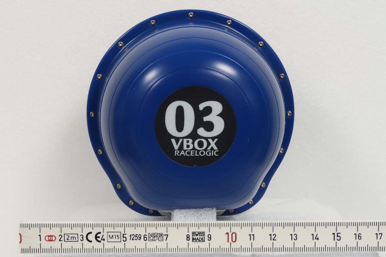
Click to zoom
Application Details
- Equipment Class
- UWB - Ultra Wideband Transmitter
- Date of Grant
- Feb 13, 2020
- Application Purpose
- Original Equipment
- Date of Application
- Feb 10, 2020
- Equipment Note
- Indoor Positioning System
- Frequency Range
- 6128.20000000 - 6655.90000000
- Company
- RACELOGIC LIMITED
- Country
- United Kingdom
Documents & Files
Document Text
Text extracted from the exhibit documents filed with the FCC. Open a document above to read the original.
Users Manual
VBOX Indoor Positioning System User Guide •01 - VBOX IPS Introduction •02 - VBOX IPS Hardware Installation •03 - VBOX IPS Rover Connection to VBOX 3i •04 - VBOX IPS Site Configuration •05 - VBOX IPS Using with a VBOX 3i/Standalone •06 - VBOX IPS Troubleshooting •VBOX IPS - PIN OUTS •VBOX IPS - Technical Specification •VBOX IPS - Upgrading Firmware •VBOX IPS - Regulatory Information 1 01 - VBOX IPS Introduction Overview VBOX Indoor Positioning System uses a network of fixed beacons in set locations that communicate with a receiver mounted on the roof of a vehicle using Ultra Wideband (UWB), to measure position and speed where you cannot use GNSS signals. A minimum of eight beacons are required and a site survey must be carried out as part of the installation, to ensure the optimum accuracy. Doing so means the exact location of each beacon is known which can then be shared with the rover enabling it to calculate its location to centimetre level accuracy. The rover features an integrated VBOX IMU04 (Inertial Measurement Unit) for precise pitch, roll and yaw angular data. It also connects directly to an IMU04 enabled VBOX 3i, enabling additional parameters from the vehicle’s CAN bus to be logged. Offering seamless integration between indoor and outdoor environments, the system can be used for high dynamic applications and the rover will automatically connect to the nearest beacons in range. Features •Can be used indoors and outdoors, switching seamlessly between environments. •Centimetre level accuracy in areas off limits to GPS based systems. •Small, rugged and low powered. •Only one rover is required, featuring an integrated VBOX IMU with Kalman filter to reduce noise and errors in the data. •Connects directly to a VBOX 3i data logger using only one cable for simple configuration. •A minimum of 8 and maximum of 250 beacons can be installed in each location allowing continuous coverage of tracks up to 3.5 km long. •Simple one time configuration either by Bluetooth or serial cable (RS232). •100 Hz update and low latency for high dynamic applications. •The rover automatically connects to the nearest beacons for optimum accuracy. •Each beacon is numbered for simple installation. https://racelogic.support/01VBOX_Automotive/VBOX_Indoor_Positioning_System/VBOX_IPS_User_Guide/ 2 Connectors https://racelogic.support/01VBOX_Automotive/VBOX_Indoor_Positioning_System/VBOX_IPS_User_Guide/ 3 02 - VBOX IPS Hardware Installation Beacon (VIPS-B-V1) Installation When first considering a VIPS installation or demonstration, it is important to understand the shape and size of the test area and thus the minimum number of beacons that will be required. The VBOX IPS will need at least 6 beacons in view at any one time to compute a solution. For a simple installation, Racelogic recommend placing the beacons in a ‘Square’ formation with spacing between the beacons of around 25–30 m, as below. If operating in an outdoor/indoor mode, then the rover will not switch to use the VBOX IPS until 6 beacons are in view. This means that it is only the first 6 beacons that will need to be placed closer together to ensure that 6 beacons are in view before the vehicle enters the test area. The remaining beacons can be placed with a greater separation so long as https://racelogic.support/01VBOX_Automotive/VBOX_Indoor_Positioning_System/VBOX_IPS_User_Guide/ 4 the vehicle is always within a 60 m radius of at least 6 beacons. For greater accuracy, it is recommended that the beacons are placed between 3 – 5 m above ground (i.e. above the roof of the test vehicle) and that each beacon varies in height by at least 300 mm to the nearest beacons, alternating in a high-low pattern. When mounting the VIPS beacons, there are a couple of considerations that need to be made. It is important when mounting the beacons that they are not mounted within at least 200 mm (or greater if possible) of an object, other than the surface the beacon is mounted to, that could cause reflections (e.g.a wall or metal structure) and that the beacons are mounted in the correct orientation in relation to the expected orientation of the Rover when in use. The beacons require a9 – 36 V power sourcethat is connected to the2 wayLemo connector. Theother Lemo connectoron the beacon is for Firmware upgrades and should be covered with the supplied splashproof plug to ensure waterproofness. The VIPS beacons have 4 magnets on the base allowing for easy installation onto any ferrous surface, however Racelogic can supply metallic plates that can attach to a tripod for quick installations. SuitableBeacon Orientations ✔ Side by side ✔ Side by side with small height difference ✔ Side by side with large height difference, tops towards each other https://racelogic.support/01VBOX_Automotive/VBOX_Indoor_Positioning_System/VBOX_IPS_User_Guide/ 5 ✗✗ Side by side with large height difference ✗✗ Tops together ✗✗ Tops to base ✗✗ Base to base ✗✗ Side to base ✗✗ Side by side with large height difference, tops away from each other https://racelogic.support/01VBOX_Automotive/VBOX_Indoor_Positioning_System/VBOX_IPS_User_Guide/ 6 Rover (VIPS-R-V2) Installation The VIPS Rover looks similar to the Beacon, however the rover contains an internal IMU and so care should be taken to ensure that the Rover is mounted on a section of the roof that has the least vibration. This is usually towards the rear of the vehicle, just in front of the rear windshield. The rover should also be mounted in a way such that it has a clear view to the beacons and away from any objects that may block that view (Roof bars, radio antennas etc). https://racelogic.support/01VBOX_Automotive/VBOX_Indoor_Positioning_System/VBOX_IPS_User_Guide/ 7 03 - VBOX IPS Rover Connection to VBOX 3i The Rover unit can connectto a standard VBOX 3i and switches seamlessly between GPS and the indoor positioning system, allowing you to use your original hardware for both outdoor and indoor testing.As the VIPS is designed to be used with IMU in…
Text truncated - open the document above for the full version.
External Photos
External Photos – 2AU5C-VIPSB01 Top Bottom Front Rear Left Right
ID Label/Location Info
74.5 124 124 48 62.50 22 48 28 87 A B 234561 57824613 E D C FF D B A E C RACELOGIC Unit 10 Swan Business Centre, Osier Way, Buckingham, MK18 1TB. Tel: +44 (0)1280 823803 1 VIPS Dimensions VIPS Dimensions Redmine No. N/A 12/03/19 12/03/19 12/03/19 A GOLDMAN S HOOPER A GOLDMAN WEIGHT: 350g A3 SHEET 1 OF 1SCALE:1:1 DWG NO. TITLE: REVISION DO NOT SCALE DRAWING MATERIAL: DATESIGNATURENAME DEBURR AND BREAK SHARP EDGES FINISH: UNLESS OTHERWISE SPECIFIED: DIMENSIONS ARE IN MILLIMETRES SURFACE FINISH: TOLERANCES: LINEAR: ANGULAR: APPV'D CHK'D DRAWN
ID Label/Location Info
C D E B F A 2314 C F E A B D 2143 DRAWN CHK'D APPV'D UNLESS OTHERWISE SPECIFIED: DIMENSIONS ARE IN MILLIMETERS SURFACE FINISH: TOLERANCES: LINEAR: +/-0.01mm ANGULAR: FINISH: DEBURR AND BREAK SHARP EDGES NAMESIGNATUREDATE MATERIAL: DO NOT SCALE DRAWING REVISION TITLE: DWG NO. SCALE:1:1 SHEET 1 OF 1 A4 Matt silver Polyester 50μm Thick Per manent Adhesive Backing Polypropylene Over laminate Hot Foil Prin ted Black WEIGHT: A GOLDMAN A ANSELL S HOOPER 27/11/19 Redmine No. N/A VIPS BEACON Serial Number Sticker STK0034 1 RACELOGIC Unit 10 Swan Business Centr e, Osier Way, Buckingham, MK18 1TB. Tel: +44 (0)1280 823803 27/11/19 27/11/19 Cutter size 48mm x 28mm 3mm Radius Corners 6V to 30V DC Power 0.5W VIPS-B-V1 FCC ID: 2AU5C-VIPSB01 IC: 25649-VIPSB01 This device contains FCC ID: SQGBT900 IC: 3147A-BT900
Internal Photos
Internal Photos – 2AU5C-VIPSB01 Beacon digital side 1 Beacon Digital side 2 Boards in housing RF board antenna side RF board component side – no shield RF board component side – with shield
RF Exposure Info
Test Number: 458-19R1 Issue Date: 2/7/2020 Page 43 of 52 Compliance Worldwide, Inc. - 357 Main Street - Sandown, NH 03873 (603) 887 3903 Fax (603) 887 6445 www.complianceworldwide.com 6. Measurement Data (continued) 6.11. Public Exposure to Radio Frequency Energy Levels (1.1307 (b)(2)) 6.11.1. SAR Test Exclusion Calculation Requirement: Portable devices as defined in § 2.1093 of this chapter operating under Part 15 are subject to radio frequency radiation exposure requirements as specified in 1.1307(b)(2) and 2.1093 of this chapter. For a 1-g SAR, the test exclusion result must be ≤ 3.0. Test Notes: The 1-g and 10-g SAR test exclusion thresholds for 100 MHz to 6 GHz at test separation distances ≤ 50 mm are determined by the following formula: SAR Test Exclusion = (1) P MAX mW Maximum power of channel, including tune-up tolerance d MIN mm Minimum test separation distance, mm (≤ 50 mm) f (GHz) GHz f (GHz) is the RF channel transmit frequency in GHz (>100 MHz and <6 GHz) (1) FCC OET 447498 - Mobile and Portable Devices RF Exposure Procedures and Equipment Authorization Policies. Result: The device under test meets the exclusion requirement detailed in FCC OET 447498. Channel: 4, 64M Input: P MAX 0.320 mW d MIN 5.000 mm f (GHz) 3.744 GHz Test Exclusion: 0.124 Limit Exemption: 3.000 1 Taken from the peak data in Section 6.5 of this test report (converted to mW). The device does not exceed the test limit exemption and therefore a routine SAR Evaluation is not required. Note: The Laird Connectivity BT900 module is used for setup and configuration of the device and is not used/operated simultaneously with the UWB radio. P MAX d MIN x √f (GHz) Test Number: 458-19R1 Issue Date: 2/7/2020 Page 44 of 52 Compliance Worldwide, Inc. - 357 Main Street - Sandown, NH 03873 (603) 887 3903 Fax (603) 887 6445 www.complianceworldwide.com 6. Measurement Data (continued) 6.11.2 RF Exposure for devices that operate above 6 GHz (1.1310) Requirements: 2.1093(b): A portable device is defined as a transmitting device designed to be used so that the radiating structure(s) of the device is/are within 20 centimeters of the body of the user. 2.1093 (d): Portable devices that transmit at frequencies above 6 GHz are to be evaluated in terms of the MPE limits specified 47 CFR 1.1310. Measurements and calculations to demonstrate compliance with MPE Field strength or power density limits for device operating above 6 GHz should be made at a minimum distance of 5 cm from the radiating source. 1.1310, Table 1: Limits for Maximum Permissible Exposure (MPE), Section (B): Limits for General Population/Uncontrolled Exposure for devices that operate between 1500 to 100,000 MHz is 1.0 mW/cm 2 using a 30 minute averaging time. Center Frequency (GHz) MPE Distance (cm) DUT Peak Output Power (dBm) DUT Antenna Gain (dBi) DUT Peak Power (mW) Power Density FCC Limit (mW/cm 2 ) (mW/cm 2 ) (W/m 2 ) (1) (2) (3) (4) (5) 6.488 5 -4.66 0.0 0.342 0.0010886 0.0108855 1 1. Reference CFR 2.1093(b): For purposes of this section, a portable device is defined as a transmitting device designed to be used so that the radiating structure(s) of the device is/are within 5 centimeters of the body of the user. 2. Section 6.7 of this test report. Measured Peak Power at 3 Meters. 3. Antenna Gain included in the measured values of Section 6.7 4. Power density is calculated from field strength measurement and antenna gain. 5. Reference CFR 1.1310, Table 1: Limits for Maximum Permissible Exposure (MPE), Section (B): Limits for General Population/Uncontrolled Exposure. Note: The Laird Connectivity BT900 module is used for setup and configuration of the device and is not used/operated simultaneously with the UWB radio. PD = OP + AG (4 x π x d²)
Test Report
Compliance Worldwide, Inc. - 357 Main Street - Sandown, NH 03873 (603) 887 3903 Fax (603) 887 6445 www.complianceworldwide.com COMPLIANCE WORLDWIDE INC. TEST REPORT 458-19 In Accordance with the Requirements of FCC TITLE 47 CFR Part 15.519, Subpart F Technical Requirements for Handheld UWB Systems ISED RSS-220, Issue 1 (March 2009) + Amendment 1 (July 2018) Devices Using Ultra-Wideband (UWB) Technology Issued to Racelogic Limited Unit 10 Swan Business Centre Osier Way Buckingham, UK MK18 1TB For the Beacon Model: VIPS-B-V1 FCC ID: 2AU5C-VIPSB01 IC: 25649-VIPSB01 Report Issued on January 20, 2020 Tested By This test report shall not be reproduced, except in full, without written permission from Compliance Worldwide, Inc. Test Number: 458-19 Issue Date: 1/20/2020 Page 2 of 52 Compliance Worldwide, Inc. - 357 Main Street - Sandown, NH 03873 (603) 887 3903 Fax (603) 887 6445 www.complianceworldwide.com Table of Contents 1. Scope .................................................................................................................................................. 3 2. Product Details ................................................................................................................................... 3 2.1. Manufacturer ............................................................................................................................. 3 2.2. Model Number ........................................................................................................................... 3 2.3. Serial Number ........................................................................................................................... 3 2.4. Description ................................................................................................................................ 3 2.5. Power Source ............................................................................................................................ 3 2.6. Hardware Revision .................................................................................................................... 3 2.7. Software Revision ..................................................................................................................... 3 2.8. Modulation Type ........................................................................................................................ 3 2.9. Operating Frequency ................................................................................................................ 3 2.10. EMC Modifications .................................................................................................................. 3 3. Product Configuration ......................................................................................................................... 3 3.1. Operational Characteristics & Software .................................................................................... 3 3.2. EUT Hardware .......................................................................................................................... 3 3.3. EUT Cables/Transducers .......................................................................................................... 3 3.4. Support Equipment ................................................................................................................... 3 3.5. Test Setup ................................................................................................................................. 4 3.6. EUT Orientation Diagram .......................................................................................................... 4 4. Measurements Parameters ................................................................................................................ 5 4.1. Measurement Equipment Used to Perform Test ...................................................................... 5 4.2. Measurement & Equipment Setup ............................................................................................ 6 4.3. Measurement Procedure .......................................................................................................... 6 4.4. Measurement Uncertainty ......................................................................................................... 6 5. Measurement Summary ..................................................................................................................... 7 6. Measurement Data ............................................................................................................................. 8 6.1. Antenna Requirement ............................................................................................................... 8 6.2. Operational Requirements ........................................................................................................ 9 6.3. UWB Bandwidth ...................................................................................................................... 11 6.4. Radiated Emissions below 960 MHz ...................................................................................... 13 6.5. Radiated Emissions above 960 MHz ...................................................................................... 22 6.6. Radiated Emissions in the GPS Bands................................................................................... 32 6.7. RMS Emissions of UWB Transmission ................................................................................... 35 6.8. Peak Emissions in a 50 MHz Bandwidth ................................................................................ 38 6.9. Conducted Emissions Test Setup ........................................................................................... 41 6.10. 99% Emission Bandwidth ..................................................................................................... 42 6.12. Public Exposure to Radio Frequency Energy Levels......…
Text truncated - open the document above for the full version.
Test Setup Photos
Test Number: 458-19 Issue Date: 1/20/2020 Page 47 of 52 Compliance Worldwide, Inc. - 357 Main Street - Sandown, NH 03873 (603) 887 3903 Fax (603) 887 6445 www.complianceworldwide.com 8. Test Images 8.1. Spurious and Harmonic Emissions – 30 kHz to 30 MHz Front Test Number: 458-19 Issue Date: 1/20/2020 Page 48 of 52 Compliance Worldwide, Inc. - 357 Main Street - Sandown, NH 03873 (603) 887 3903 Fax (603) 887 6445 www.complianceworldwide.com 8. Test Images 8.2. Spurious and Harmonic Emissions – 30 kHz to 30 MHz Rear Test Number: 458-19 Issue Date: 1/20/2020 Page 49 of 52 Compliance Worldwide, Inc. - 357 Main Street - Sandown, NH 03873 (603) 887 3903 Fax (603) 887 6445 www.complianceworldwide.com 8. Test Images 8.3. Spurious and Harmonic Emissions – 30 MHz to 1 GHz Rear Test Number: 458-19 Issue Date: 1/20/2020 Page 50 of 52 Compliance Worldwide, Inc. - 357 Main Street - Sandown, NH 03873 (603) 887 3903 Fax (603) 887 6445 www.complianceworldwide.com 8. Test Images 8.4. Spurious and Harmonic Emissions – 1 to 18 GHz Front Test Number: 458-19 Issue Date: 1/20/2020 Page 51 of 52 Compliance Worldwide, Inc. - 357 Main Street - Sandown, NH 03873 (603) 887 3903 Fax (603) 887 6445 www.complianceworldwide.com 8. Test Images 8.5. Spurious and Harmonic Emissions – 1 to 18 GHz Rear Test Number: 458-19 Issue Date: 1/20/2020 Page 52 of 52 Compliance Worldwide, Inc. - 357 Main Street - Sandown, NH 03873 (603) 887 3903 Fax (603) 887 6445 www.complianceworldwide.com 8. Test Images 8.6. Spurious and Harmonic Emissions – 18 to 40 GHz Side View
Contact Information
Applicant
Simon Hooper(Hardware Manager)
Test Firm
Compliance Worldwide, Inc.Deb Bourbeau
Technical Specifications
| # | Rule Parts | Frequency Range | Power Output |
|---|---|---|---|
| 2 | 15F | 6.13 GHz - 6.66 GHz | - |
Other Applications from RACELOGIC LIMITED
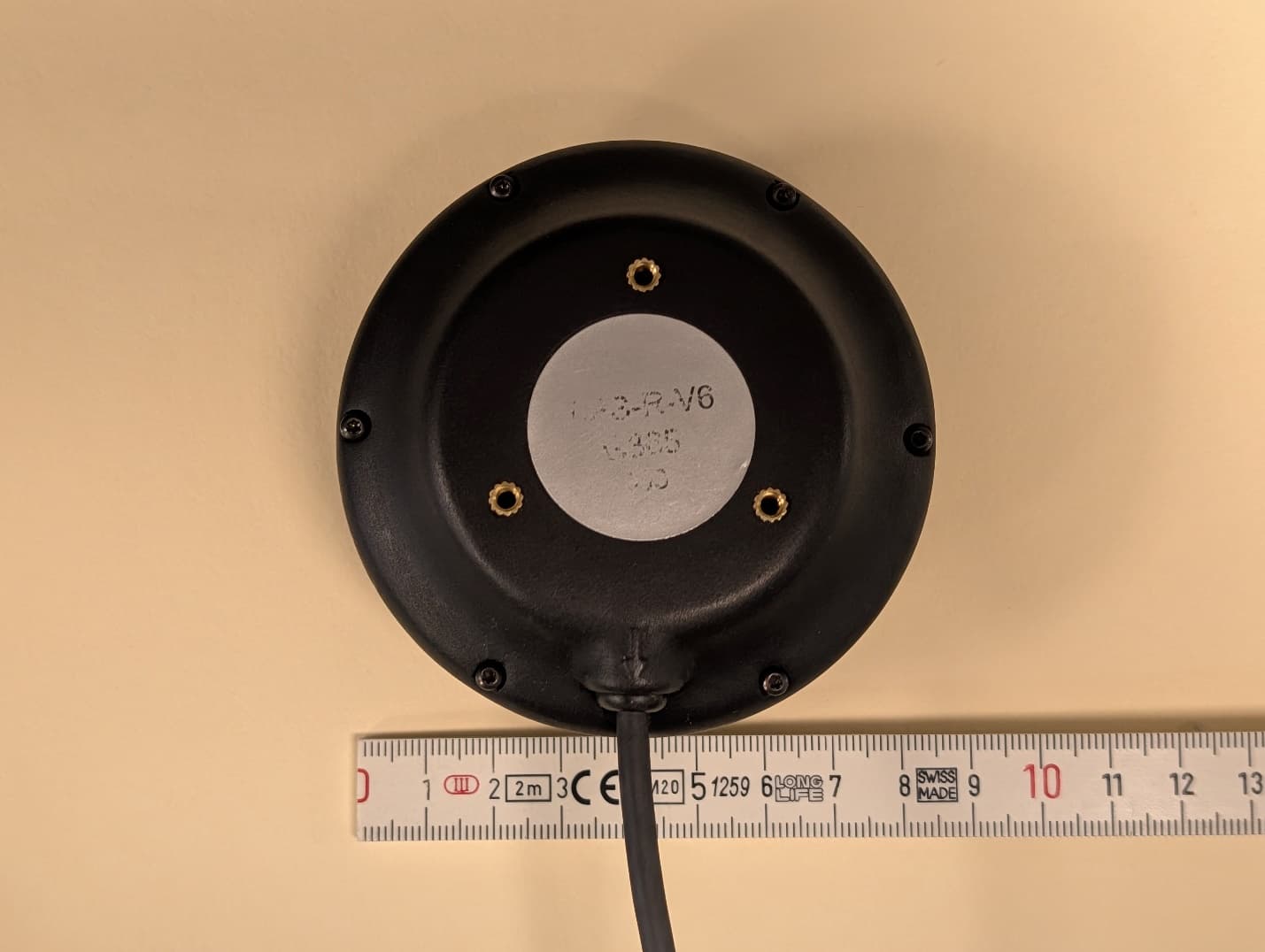
2AU5C-VIPSR06
Jul 01, 2026The VIPS Rover V6 is a highly effective indoor positioning solution.
Equipment Class
UWB - Ultra Wideband Transmitter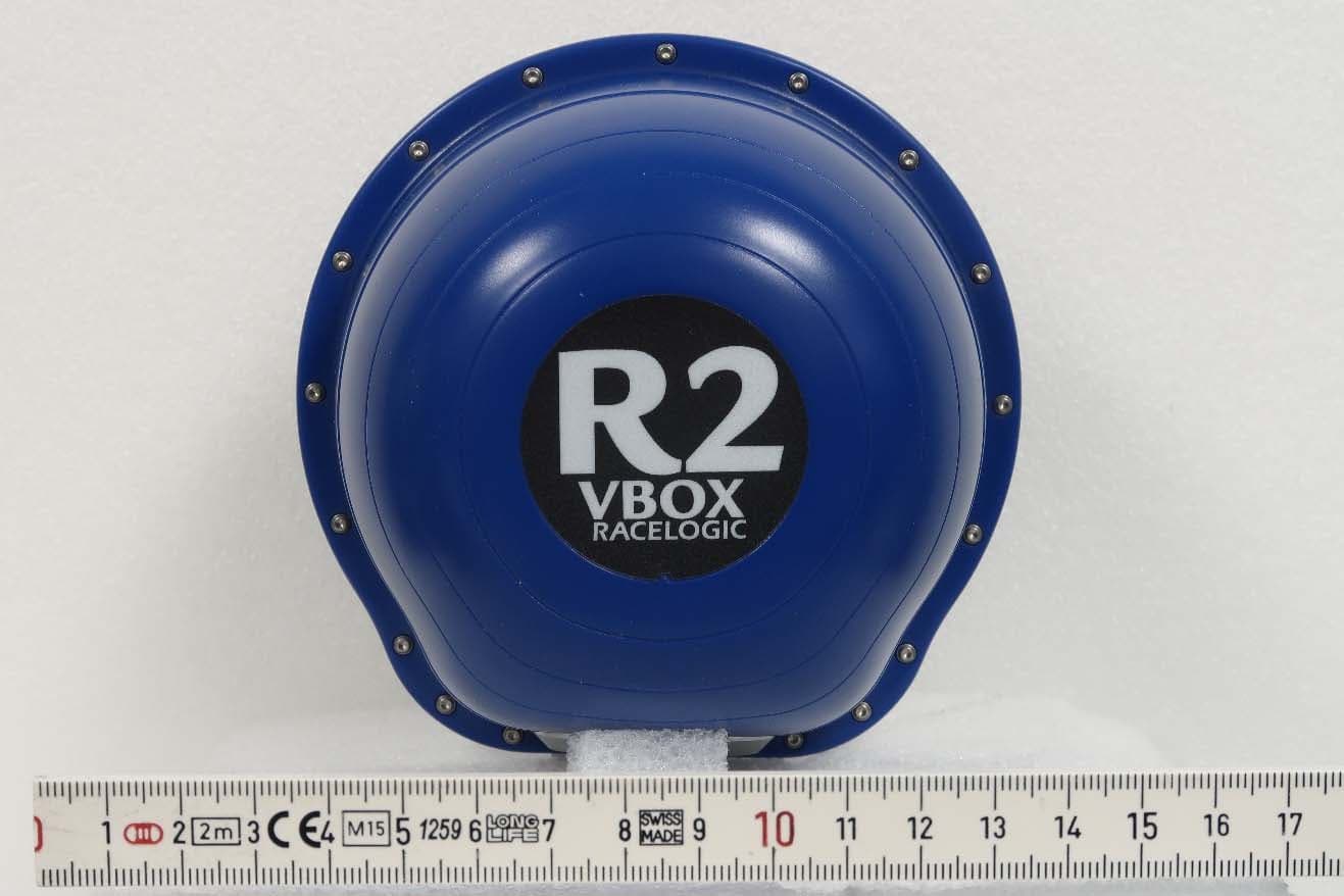
2AU5C-VIPSR01
Feb 13, 2020Indoor Positioning System
Equipment Class
UWB - Ultra Wideband Transmitter