2AU6EDNS-5B12Wireless USB Adapter
Shenzhen Denos Trade Co., Ltd.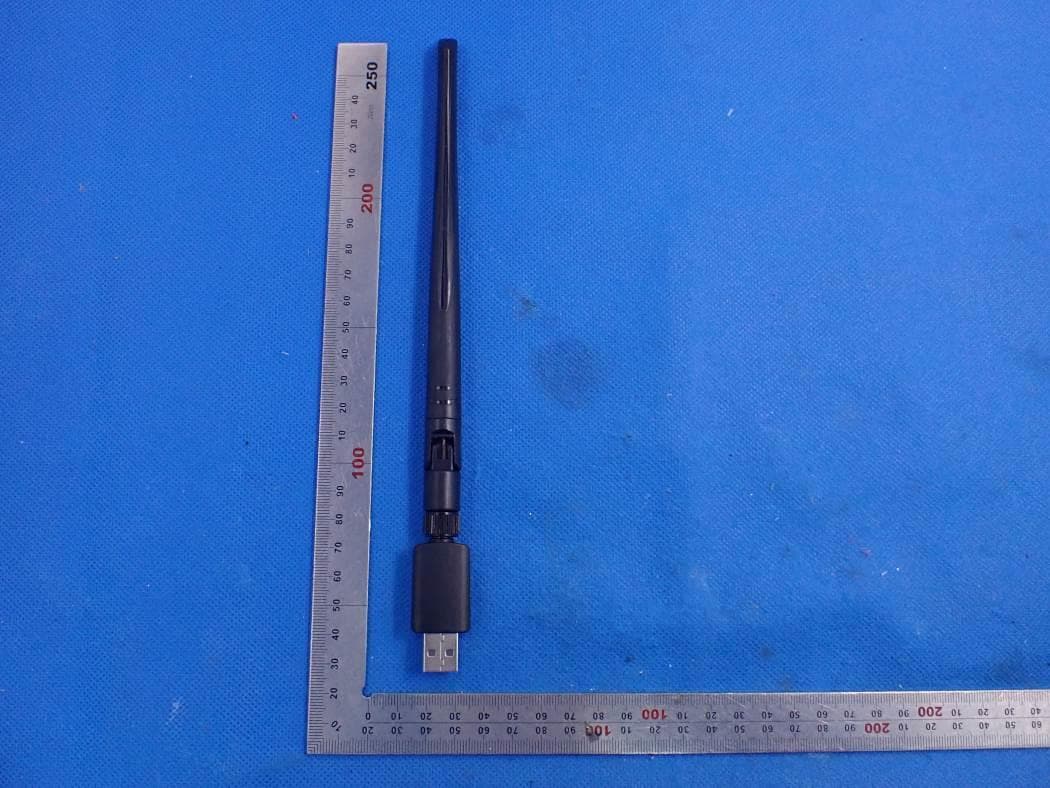
Click to zoom
Application Details
- Equipment Class
- DTS - Digital Transmission System
- Date of Grant
- Jan 04, 2021
- Application Purpose
- Original Equipment
- Date of Application
- Jan 04, 2021
- Equipment Note
- Wireless USB Adapter
- Frequency Range
- 2412.00000000 - 2462.00000000
- Country
- China
Documents & Files
Document Text
Text extracted from the exhibit documents filed with the FCC. Open a document above to read the original.
Users Manual
WiFi Adapter (without Driver) User Guide(For Windows) Easy Setup: Plug & Play automatically Step 1 Connect the USB interface of the WiFi adapter to computer USB port (Supprt USB2.0/3.0) Step 2 The computer control panel opens the AutoPlay function or check “Driver_Disk” to install the driver software Step 3 Select proper file for your system”Windows/Mac” Choose your network and enter the password WiFi Adapter (ohne Fahrer) Benutzerhandbuch (Für Windows) Einfache Einstellung: Stecker & Automatisch spielen Schritt 1 Verbinden Sie die USB Schnittstelle des WiFi Adapter mit dem USB Anschluss des Computers (Unterstützung USB2.0 / 3.0) Schritt 2 Das Computer-Kontrollfeld öffnet die Autoplay-Funktion oder überprüft "Driver_Disk", um die Treibersoftware zu installieren Schritt 3 Wählen Sie die passende Datei für Ihr "Windows / Mac" System. Wählen Sie Ihr Netzwerk und Ihr Passwort eingeben. Wählen Sie die passende Datei für Ihr "Windows / Mac" System. Doppelklick en und ausführen WiFi Adaptateur (sans chauffeur) Guide de l'utilisateur (Pour Windows) Installation facile: Fiche & Jouer automatiquement Étape 1 Connectez l'interface USB de WiFi adaptateur au port USB de l'ordinateur (Support USB2.0 / 3.0) Étape 2 Le panneau de commande de l'ordinateur ouvre la fonction de lecture automatique ou vérifie "Driver_Disk" pour installer le pilote Étape 3 Choisissez le fichier approprié pour votre système "Windows / Mac" Choisissez votre réseau et entrez votre mot de passe Choisissez le fichier approprié pour votre système "Windows / Mac" Double-cliq uez et lancez WiFiアダプタ (ドライバなし) ユーザーガイド(Windowsの場合) 簡単セットアップ: 自動的にプラグ&起動 ステップ1 WiFiアダプタのUSBインターフェイスをコンピュータのUSBポートに接続します。 (サポートUSB2.0 / 3.0) ステップ2 コンピュータのコントロールパネルが自動再生機能を開くか、または「ドライバディスク」をチェックしてドライバ ソフトウェアをインストールします。 ステップ3 "Windows もしくは Mac"のお使いのシステムに適したファイルを選択してください。 "Windows もしくは Mac"のお使いのシステムに適したファイルを選択してください。 ダブルクリッ クして実行し ます。 ネットワークを選択してパスワードを入力してください。 WiFi Adaptador (Sin conductor) Guía del usuario (Para Windows) Configuración fácil: Enchufe & Jugar automáticamente Paso 1 Conecte la interfaz USB del WiFi adaptador al puerto USB de la computadora (Compatible con USB2.0 / 3.0) Paso 2 El panel de control de computadora abre la función de reproducción automática o marca "Driver_Disk" para instalar el software del controlador Paso 3 Elija el archivo apropiado para su sistema "Windows / Mac" Elija su red e ingrese su contraseña Elija el archivo apropiado para su sistema "Windows / Mac" Hacer doble clic y ejecutar WiFi Adattatore (Nessun Driver) Guida utente (Per Windows) Facile installazione: Spina & Gioca automaticamente Passo 1 Collegare l'interfaccia USB dell WiFi adattatore alla porta USB del computer (Supporto USB 2.0 / 3.0) Passo 2 Il pannello di controllo del computer apre la funzione di autoplay o controlla "Driver_Disk" per installare il software del driver Passo 3 Scegli il file appropriato per il tuo sistema "Windows / Mac" Scegli la tua rete e inserisci la tua password Scegli il file appropriato per il tuo sistema "Windows / Mac" Doppio clic ed esegui NOTE: This equipment has been tested and found to comply with the limits for a Class B digital device, pursuant to part 15 of the FCC Rules. These limits are designed to provide reasonable protection against harmful interference in a residential installation. This equipment generates uses and can radiate radio frequency energy and, if not installed and used in accordance with the instructions, may cause harmful interference to radio communications. However, there is no guarantee that interference will not occur in a particular installation. If this equipment does cause harmful interference to radio or television reception, which can be determined by turning the equipment off and on, the user is encouraged to try to correct the interference by one or more of the following measures: - Reorient or relocate the receiving antenna. - Increase the separation between the equipment and receiver. -Connect the equipment into an outlet on a circuit different from that to which the receiver is connected. -Consult the dealer or an experienced radio/TV technician for help Changes or modifications not expressly approved by the party responsible for compliance could void the user's authority to operate the equipment. This device complies with Part 15 of the FCC Rules. Operation is subject to the following two conditions: (1) this device may not cause harmful interference, and (2) this device must accept any interference received, including interference that may cause undesired operation.
Cover Letter(s)
Shenzhen Denos Trade Co., Ltd. Dec.31, 2020 Office of Engineering Technology Federal Communications Commission 7435 Oakland Mills Road Columbia, MD 21046 USA Subject: Explanation of differences between product types FCC ID : 2AU6EDNS-5B12 Model Number: 5B12, 5B10 To Whom It May Concern: We, The Shenzhen Denos Trade Co., Ltd. hereby declare that the model : 5B10 is identical with the model : 5B12, except the model name. Except for the different above, no other modification is performed. Sincerely, Signature: Shenzhen Denos Trade Co., Ltd. Contact person: ZhiXiong Fang
Cover Letter(s)
Shenzhen Denos Trade Co., Ltd. Agent Authorization Company: Shenzhen Denos Trade Co., Ltd. Address: Room 610, Shibida Building, No. 55 ZhenHua Rd, Futian District, Shen Zhen, GuangDong, China Product Name: Wireless USB Adapter Model Number(s): 5B12, 5B10 Product Description: Wireless USB Adapter We authorize MiCOM Labs Inc., 575 Boulder Court, Pleasanton, California 94566, USA, to act on our behalf on all matters concerning the certification of above named equipment. We declare that MiCOM Labs Inc. is allowed to forward all information related to the approval and certification of equipment to the regulatory agencies as required and to discuss any issues concerning the approval application. Any and all acts carried out by MiCOM Labs on our behalf shall have the same effect as acts of our own. Signature: Date: 2020-12-31 Name: ZhiXiong Fang Company: Shenzhen Denos Trade Co., Ltd.
Cover Letter(s)
Shenzhen Denos Trade Co., Ltd. Office of Engineering Technology Federal Communications Commission 7435 Oakland Mills Road Columbia, MD 21046 USA Date: 2020-12-31 Subject; Request for Confidentiality FCC ID: 2AU6EDNS-5B12 To Whom It May Concern, Pursuant to the provisions of the Commission’s rules Title 47 Sections §0.457 and §0.459, we are requesting the Commission to withhold the following attachment(s) as confidential documents from public disclosure indefinitely. These documents contain detailed system and equipment descriptions and are considered as proprietary information in operation of the equipment. The public disclosure of these documents might be harmful to our company and would give competitors an unfair advantage in the market. Schematic Diagram Block Diagram Parts List Operational Description FCC Software Security Description In additional to above mentioned documents, in order to comply with the marketing regulations in Title 47 CFR §2.803 and the importation rules in Title 47 CFR §2.1204, while ensuring that business sensitive information remains confidential until the actual marketing of newly authorized devices, we request Short Term Confidentiality of the following attachment(s); External Photos Test Setup Photos Internal Photos User Manual For 45 days, pursuant to Public Notice DA 04-1705. OR For 180 days pursuant to KDB 726920 D01. It is our understanding that all measurement test reports, FCC ID label format and correspondence during the certification review process cannot be granted as confidential documents and this information will be available for public review once the grant of equipment authorization is issued. Sincerely Shenzhen Denos Trade Co., Ltd. Contact person: ZhiXiong Fang
External Photos
External Photos TOP VIEW OF EUT BOTTOM VIEW OF EUT FRONT VIEW OF EUT BACK VIEW OF EUT LEFT VIEW OF EUT RIGHT VIEW OF EUT
ID Label/Location Info
FCC ID Label Location FCC ID: 2AU6EDNS-5B12
Internal Photos
Internal Photos OPEN VIEW OF EUT-1 OPEN VIEW OF EUT-2 OPEN VIEW OF EUT-3 INTERNAL VIEW OF EUT-1 Antenna INTERNAL VIEW OF EUT-2
RF Exposure Info
RF EXPOSURE EVALUATION 1. PRODUCT INFORMATION Product Description Wireless USB Adapter Model Name 5B12, 5B10 FCC ID 2AU6EDNS-5B12 2. EVALUATION METHOD According to 447498 D01 General RF Exposure Guidance v05 The 1-g and 10-g SAR test exclusion thresholds for 100 MHz to 6 GHz at test separation distances ≤ 50 mm are determined by: [(max. power of channel, including tune-up tolerance, mW)/(min. test separation distance, mm)] ·[√f(GHz)] ≤ 3.0 for 1-g SAR and ≤ 7.5 for 10-g extremity SAR. Where f(GHz) is the RF channel transmit frequency in GHz Power and distance are rounded to the nearest mW and mm before calculation 3. CALCULATION According to the follow transmitter output power(P t )formula: P t =(E x d) 2 /(30 x g t ) P t =transmitter output power in watts g t =numeric gain of the transmitting antenna (unitess) E=electric field strength in V/m d=measurement distance in meters (m) For 2.4G WIFI P t =9.19dBm=8.30mW The result for RF exposure evaluation SAR=(8.30mW /5mm) .[√2.412(GHz)]= 2.57<3.0 for 1-g SAR For 5G WIFI P t =5.72dBm=3.73mW The result for RF exposure evaluation SAR=(3.73mW /5mm) .[√5.19(GHz)]=1.70<3.0 for 1-g SAR Note: The 2.4G WIFI and 5G WIFI can not transmit simultaneously. 4. CONCLUSION The SAR evaluation is not required.
Test Report
Page 1 of 86 Report No.: AGC00688201219FE05 FCC ID : 2AU6EDNS-5B12 APPLICATION PURPOSE : Original Equipment PRODUCT DESIGNATION : Wireless USB Adapter BRAND NAME : Techkey MODEL NAME : 5B12, 5B10 APPLICANT : Shenzhen Denos Trade Co., Ltd. DATE OF ISSUE : Dec. 30, 2020 STANDARD(S) TEST PROCEDURE(S) : FCC Part 15.247 REPORT VERSION : V1.0 Attestation of Global Compliance (Shenzhen) Co., Ltd FCC Test Report Report No.: AGC00688201219FE05 Page 2 of 86 EPORT REVISE RECORD Report Version Revise Time Issued Date Valid Version Notes V1.0 / Dec. 30, 2020 Valid Initial Release Report No.: AGC00688201219FE05 Page 3 of 86 TABLE OF CONTENTS 1. VERIFICATION OF CONFORMITY ............................................................................................................... 5 2. GENERAL INFORMATION ............................................................................................................................ 6 2.1. PRODUCT DESCRIPTION ..................................................................................................................... 6 2.2. TABLE OF CARRIER FREQUENCYS ..................................................................................................... 6 2.3. IEEE 802.11N MODULATION SCHEME .................................................................................................. 7 2.4. RELATED SUBMITTAL(S) / GRANT (S) .................................................................................................. 7 2.5. TEST METHODOLOGY .......................................................................................................................... 7 2.6. SPECIAL ACCESSORIES ....................................................................................................................... 7 2.7. EQUIPMENT MODIFICATIONS .............................................................................................................. 7 2.8. ANTENNA REQUIREMENT .................................................................................................................... 8 3. MEASUREMENT UNCERTAINTY ................................................................................................................. 9 4. DESCRIPTION OF TEST MODES ............................................................................................................... 10 5. SYSTEM TEST CONFIGURATION ............................................................................................................. 11 5.1. CONFIGURATION OF EUT SYSTEM .................................................................................................... 11 5.2. EQUIPMENT USED IN EUT SYSTEM .................................................................................................... 11 5.3. SUMMARY OF TEST RESULTS ............................................................................................................. 11 6. TEST FACILITY ........................................................................................................................................... 12 7. OUTPUT POWER ........................................................................................................................................ 13 7.1. MEASUREMENT PROCEDURE ........................................................................................................... 13 7.2. TEST SET-UP (BLOCK DIAGRAM OF CONFIGURATION) ................................................................... 13 7.3. LIMITS AND MEASUREMENT RESULT ............................................................................................... 14 8. 6 DB BANDWIDTH ...................................................................................................................................... 16 8.1. MEASUREMENT PROCEDURE ........................................................................................................... 16 8.2. TEST SET-UP (BLOCK DIAGRAM OF CONFIGURATION) ................................................................... 16 8.3. LIMITS AND MEASUREMENT RESULTS ............................................................................................. 17 9. CONDUCTED SPURIOUS EMISSION ........................................................................................................ 25 Report No.: AGC00688201219FE05 Page 4 of 86 9.1. MEASUREMENT PROCEDURE ........................................................................................................... 25 9.2. TEST SET-UP (BLOCK DIAGRAM OF CONFIGURATION) ................................................................... 25 9.3. MEASUREMENT EQUIPMENT USEDJN ............................................................................................. 25 9.4. LIMITS AND MEASUREMENT RESULT ............................................................................................... 25 10. MAXIMUM CONDUCTED OUTPUT POWER SPECTRAL DENSITY ....................................................... 42 10.1 MEASUREMENT PROCEDURE .......................................................................................................... 42 10.2 TEST SET-UP (BLOCK DIAGRAM OF CONFIGURATION) .................................................................. 42 10.3 MEASUREMENT EQUIPMENT USED ................................................................................................. 42 10.4 LIMITS AND MEASUREMENT RESULT .............................................................................................. 42 11. RADIATED EMISSION ............................................................................................................................... 50 11.1. MEASUREMENT PROCEDURE ......................................................................................................... 50 11.2. TEST SETUP ....................................................................................................................................... 51 11.3. LIMITS AND MEASUREMENT RESULT ......…
Text truncated - open the document above for the full version.
Test Report
Report No.: AGC00688201219FE05 Page 41 of 86 TEST PLOT OF OUT OF BAND EMISSIONS THE WORST CASE OF 802.11n40 FOR MODULATION IN HIGH CHANNEL Note: Emissions from 2483.5-2500MHz which fall in the restricted bands had been considered with the radiated emission limits specified. Report No.: AGC00688201219FE05 Page 42 of 86 10. MAXIMUM CONDUCTED OUTPUT POWER SPECTRAL DENSITY 10.1 MEASUREMENT PROCEDURE (1). Connect EUT RF output port to the Spectrum Analyzer through an RF attenuator (2). Set the EUT Work on the top, the middle and the bottom operation frequency individually. (3). Set SPA Trace 1 Max hold, then View. Note: The method of PKPSD in the ANSI C63.10 (2013) item 11.10 was used in this testing. 10.2 TEST SET-UP (BLOCK DIAGRAM OF CONFIGURATION) Refer To Section 8.2. 10.3 MEASUREMENT EQUIPMENT USED Refer To Section 6. 10.4 LIMITS AND MEASUREMENT RESULT TEST ITEM POWER SPECTRAL DENSITY TEST MODE 802.11b with data rate 1 Channel No. Power density (dBm/20kHz) Power density (dBm/3kHz) Limit (dBm/3kHz) Result Low Channel -5.502 -13.74 8 Pass Middle Channel -5.941 -14.18 8 Pass High Channel -6.113 -14.35 8 Pass TEST ITEM POWER SPECTRAL DENSITY TEST MODE 802.11g with data rate 6 Channel No. Power density (dBm/20kHz) Power density (dBm/3kHz) Limit (dBm/3kHz) Result Low Channel -10.789 -19.03 8 Pass Middle Channel -10.700 -18.94 8 Pass High Channel -10.534 -18.77 8 Pass Report No.: AGC00688201219FE05 Page 43 of 86 TEST ITEM POWER SPECTRAL DENSITY TEST MODE 802.11n 20 with data rate 6.5 Channel No. Power density (dBm/20kHz) Power density (dBm/3kHz) Limit (dBm/3kHz) Result Low Channel -9.984 -18.22 8 Pass Middle Channel -10.070 -18.31 8 Pass High Channel -10.196 -18.44 8 Pass TEST ITEM POWER SPECTRAL DENSITY TEST MODE 802.11n 40 with data rate 13.5 Channel No. Power density (dBm/20kHz) Power density (dBm/3kHz) Limit (dBm/3kHz) Result Low Channel -13.737 -21.98 8 Pass Middle Channel -13.181 -21.42 8 Pass High Channel -13.738 -21.98 8 Pass Note: PSD Standard Measurement = Test Measurement -10Log (20KHz / 3KHz) Report No.: AGC00688201219FE05 Page 44 of 86 802.11b TEST RESULT TEST PLOT OF SPECTRAL DENSITY FOR LOW CHANNEL TEST PLOT OF SPECTRAL DENSITY FOR MIDDLE CHANNEL Report No.: AGC00688201219FE05 Page 45 of 86 TEST PLOT OF SPECTRAL DENSITY FOR HIGH CHANNEL 802.11g TEST RESULT TEST PLOT OF SPECTRAL DENSITY FOR LOW CHANNEL Report No.: AGC00688201219FE05 Page 46 of 86 TEST PLOT OF SPECTRAL DENSITY FOR MIDDLE CHANNEL TEST PLOT OF SPECTRAL DENSITY FOR HIGH CHANNEL Report No.: AGC00688201219FE05 Page 47 of 86 802.11n 20 TEST RESULT TEST PLOT OF SPECTRAL DENSITY FOR LOW CHANNEL TEST PLOT OF SPECTRAL DENSITY FOR MIDDLE CHANNEL Report No.: AGC00688201219FE05 Page 48 of 86 TEST PLOT OF SPECTRAL DENSITY FOR HIGH CHANNEL 802.11n 40 TEST RESULT TEST PLOT OF SPECTRAL DENSITY FOR LOW CHANNEL Report No.: AGC00688201219FE05 Page 49 of 86 TEST PLOT OF SPECTRAL DENSITY FOR MIDDLE CHANNEL TEST PLOT OF SPECTRAL DENSITY FOR HIGH CHANNEL Report No.: AGC00688201219FE05 Page 50 of 86 11. RADIATED EMISSION 11.1. MEASUREMENT PROCEDURE 1. The EUT was placed on the top of the turntable 0.8 or 1.5 meter above ground. The phase center of the receiving antenna mounted on the top of a height-variable antenna tower was placed 3 meters far away from the turntable. 2. Power on the EUT and all the supporting units. The turntable was rotated by 360 degrees to determine the position of the highest radiation. 3. The height of the broadband receiving antenna was varied between one meter and four meters above ground to find the maximum emissions field strength of both horizontal and vertical polarization. 4. For each suspected emissions, the antenna tower was scan (from 1 M to 4 M) and then the turntable was rotated (from 0 degree to 360 degrees) to find the maximum reading. 5. Set the test-receiver system to Peak or CISPR quasi-peak Detect Function with specified bandwidth under Maximum Hold Mode. 6. For emissions above 1GHz, use 1MHz RBW and 3MHz VBW for peak reading. Place the measurement antenna away from each area of the EUT determined to be a source of emissions at the specified measurement distance, while keeping the measurement antenna aimed at the source of emissions at each frequency of significant emissions, with polarization oriented for maximum response. The measurement antenna may have to be higher or lower than the EUT, depending on the radiation pattern of the emission and staying aimed at the emission source for receiving the maximum signal. The final measurement antenna elevation shall be that which maximizes the emissions. The measurement antenna elevation for maximum emissions shall be restricted to a range of heights of from 1 m to 4 m above the ground or reference ground plane. 7. When the radiated emissions limits are expressed in terms of the average value of the emissions, and pulsed operation is employed, the measurement field strength shall be determined by averaging over one complete pulse train, including blanking intervals, as long as the pulse train does not exceed 0.1 seconds. As an alternative (provided the transmitter operates for longer than 0.1 seconds) or in cases where the pulse train exceeds 0.1 seconds, the measured field strength shall be determined from the average absolute voltage during a 0.1 second interval during which the field strength is at its maximum values. 8.If the emissions level of the EUT in peak mode was 3 dB lower than the average limit specified, then testing will be stopped and peak values of EUT will be reported, otherwise, the emissions which do not have 3 dB margin will be repeated one by one using the quasi-peak method for below 1GHz. 9. For testing above 1GHz, the emissions level of the EUT in peak mode was lower than average limit (that means the emissions level in peak mode also complies with the limit in average mode), then testing will be stopped and peak values of EUT will be reported, otherwise, the emissions will be measured in average mode again and reported. 10. In ca…
Text truncated - open the document above for the full version.
Test Report
Report No.: AGC00688201219FE05 Page 73 of 86 EUT Wireless USB Adapter Model Name 5B12 Temperature 25°C Relative Humidity 60% Pressure 960hPa Test Voltage Normal Voltage Test Mode 802.11n 40with data rate 13.5 2452MHZ Antenna Horizontal PK AV RESULT: PASS Report No.: AGC00688201219FE05 Page 74 of 86 EUT Wireless USB Adapter Model Name 5B12 Temperature 25°C Relative Humidity 60% Pressure 960hPa Test Voltage Normal Voltage Test Mode 802.11n 40 with data rate 13.5 2452MHZ Antenna Vertical PK AV RESULT: PASS Report No.: AGC00688201219FE05 Page 75 of 86 13. FCC LINE CONDUCTED EMISSION TEST 13.1. LIMITS OF LINE CONDUCTED EMISSION TEST Frequency Maximum RF Line Voltage Q.P.( dBuV) Average( dBuV) 150kHz~500kHz 66-56 56-46 500kHz~5MHz 56 46 5MHz~30MHz 60 50 Note: 1. The lower limit shall apply at the transition frequency. 2. The limit decreases linearly with the logarithm of the frequency in the range 0.15 MHz to 0.50 MHz. 13.2. BLOCK DIAGRAM OF LINE CONDUCTED EMISSION TEST EUT & Support Units Report No.: AGC00688201219FE05 Page 76 of 86 13.3. PRELIMINARY PROCEDURE OF LINE CONDUCTED EMISSION TEST 1. The equipment was set up as per the test configuration to simulate typical actual usage per the user’s manual. When the EUT is a tabletop system, a wooden table with a height of 0.8 meters is used and is placed on the ground plane as per ANSI C63.10 (see Test Facility for the dimensions of the ground plane used). When the EUT is a floor-standing equipment, it is placed on the ground plane which has a 3-12 mm non-conductive covering to insulate the EUT from the ground plane. 2. Support equipment, if needed, was placed as per ANSI C63.10. 3. All I/O cables were positioned to simulate typical actual usage as per ANSI C63.10. 4. All support equipments received AC120V/60Hz power from a LISN, if any. 5. The EUT received DC 5V power from PC which received AC120V/60Hz power from a LISN. 6. The test program was started. Emissions were measured on each current carrying line of the EUT using a spectrum Analyzer / Receiver connected to the LISN powering the EUT. The LISN has two monitoring points: Line 1 (Hot Side) and Line 2 (Neutral Side). Two scans were taken: one with Line 1 connected to Analyzer / Receiver and Line 2 connected to a 50 ohm load; the second scan had Line 1 connected to a 50 ohm load and Line 2 connected to the Analyzer / Receiver. 7. Analyzer / Receiver scanned from 150 kHz to 30MHz for emissions in each of the test modes. 8. During the above scans, the emissions were maximized by cable manipulation. 9. The test mode(s) were scanned during the preliminary test. Then, the EUT configuration and cable configuration of the above highest emission level were recorded for reference of final testing. 13.4. FINAL PROCEDURE OF LINE CONDUCTED EMISSION TEST 1. EUT and support equipment was set up on the test bench as per step 2 of the preliminary test. 2. A scan was taken on both power lines, Line 1 and Line 2, recording at least the six highest emissions. Emission frequency and amplitude were recorded into a computer in which correction factors were used to calculate the emission level and compare reading to the applicable limit. If EUT emission level was less –2dB to the A.V. limit in Peak mode, then the emission signal was re-checked using Q.P and Average detector. 3. The test data of the worst case condition(s) was reported on the Summary Data page. Report No.: AGC00688201219FE05 Page 77 of 86 13.5. TEST RESULT OF LINE CONDUCTED EMISSION TEST Line Conducted Emission Test Line 1-L Report No.: AGC00688201219FE05 Page 78 of 86 Line Conducted Emission Test Line 2-N RESULT: PASS Report No.: AGC00688201219FE05 Page 79 of 86 APPENDIX A: PHOTOGRAPHS OF TEST SETUP FCC RADIATED EMISSION TEST SETUP BELOW 1GHZ FCC RADIATED EMISSION TEST SETUP ABOVE 1GHZ Report No.: AGC00688201219FE05 Page 80 of 86 CONDUCTED EMISSION TEST SETUP CONDUCTED TEST SETUP Report No.: AGC00688201219FE05 Page 81 of 86 APPENDIX B: PHOTOGRAPHS OF EUT TOP VIEW OF EUT BOTTOM VIEW OF EUT Report No.: AGC00688201219FE05 Page 82 of 86 FRONT VIEW OF EUT BACK VIEW OF EUT Report No.: AGC00688201219FE05 Page 83 of 86 LEFT VIEW OF EUT RIGHT VIEW OF EUT Report No.: AGC00688201219FE05 Page 84 of 86 OPEN VIEW OF EUT-1 OPEN VIEW OF EUT-2 Report No.: AGC00688201219FE05 Page 85 of 86 OPEN VIEW OF EUT-3 INTERNAL VIEW OF EUT-1 Antenna Report No.: AGC00688201219FE05 Page 86 of 86 INTERNAL VIEW OF EUT-2 ----END OF REPORT---- Conditions of Issuance of Test Reports 1. All samples and goods are accepted by the Attestation of Global Compliance (Shenzhen) Co., Ltd (the “Company”) solely for testing and reporting in accordance with the following terms and conditions. The company provides its services on the basis that such terms and conditions constitute express agreement between the company and any person, firm or company requesting its services (the “Clients”). 2. Any report issued by Company as a result of this application for testing services (the “Report”) shall be issued in confidence to the Clients and the Report will be strictly treated as such by the Company. It may not be reproduced either in its entirety or in part and it may not be used for advertising or other unauthorized purposes without the written consent of the Company. The Clients to whom the Report is issued may, however, show or send it, or a certified copy thereof prepared by the Company to its customer, supplier or other persons directly concerned. The Company will not, without the consent of the Clients, enter into any discussion or correspondence with any third party concerning the contents of the Report, unless required by the relevant governmental authorities, laws or court orders. 3.The Company shall not be called or be liable to be called to give evidence or testimony on the Report in a court of law without its prior written consent, unless required by the relevant governmental authorities, laws or court orders. 4. The non-CMA report issued by AGC is only permitted to be used by the client …
Text truncated - open the document above for the full version.
Test Setup Photos
Test Setup Photos FCC LINE CONDUCTED EMISSION TEST SETUP FCC RADIATED EMISSION TEST SETUP BELOW 1GHZ FCC RADIATED EMISSION TEST SETUP ABOVE 1GHZ CONDUCTED TEST SETUP
Contact Information
Applicant
ZhiXiong Fang
Technical Contact
Test Firm
Attestation of Global Compliance (Shenzhen) Co., LDoris Li
[email protected]+86-755-25234088
Technical Specifications
| # | Rule Parts | Frequency Range | Power Output |
|---|---|---|---|
| 1 | 15C | 2.41 GHz - 2.46 GHz | 32.50 mW |
Other Applications from Shenzhen Denos Trade Co., Ltd.
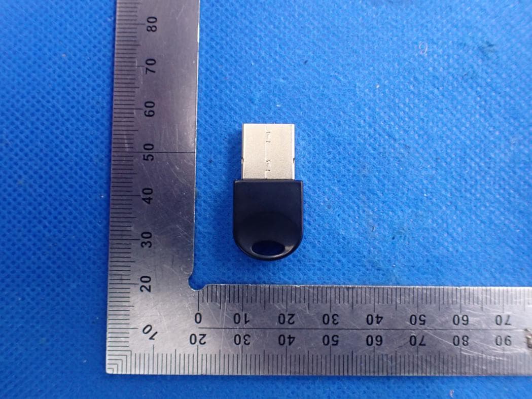
2AU6EDNS-T002
Dec 30, 2020Bluetooth USB Adapter
Equipment Class
DSS - Part 15 Spread Spectrum Transmitter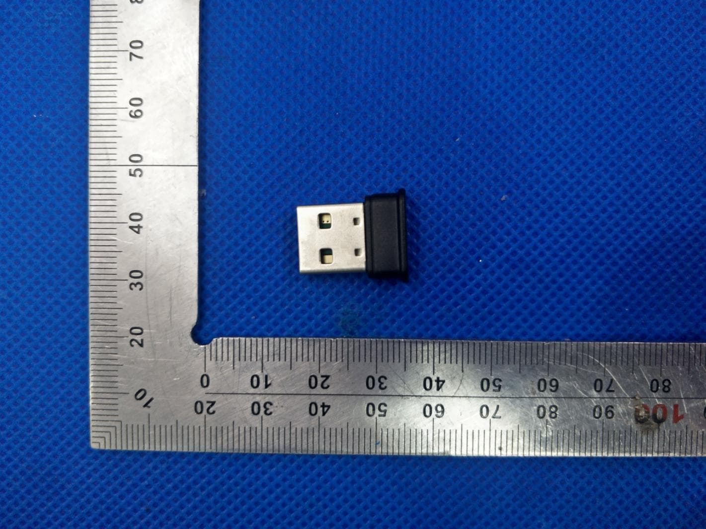
2AU6EDNS-T001
Jul 07, 2020Bluetooth USB Adapter
Equipment Class
DSS - Part 15 Spread Spectrum Transmitter