2AU75AT-88EYEWEAR SMART
Shenzhen Aita Technology Co., Ltd.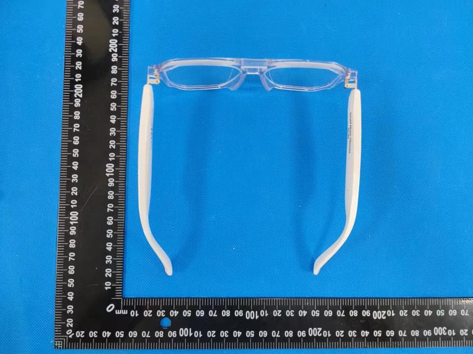
Click to zoom
Application Details
- Equipment Class
- DSS - Part 15 Spread Spectrum Transmitter
- Date of Grant
- Mar 23, 2022
- Application Purpose
- Original Equipment
- Date of Application
- Mar 23, 2022
- Equipment Note
- EYEWEAR SMART
- Frequency Range
- 2402.00000000 - 2480.00000000
- Country
- China
Documents & Files
Document Text
Text extracted from the exhibit documents filed with the FCC. Open a document above to read the original.
Users Manual
User Manual ➢Introduction: Thanks for choosing our products! Please carefully read this manual book before using so that the products can be used in the best way and avoid dangerous and illegal operation.It will not be advised if some contents of this manual book changed for a better function or performance. ➢Reminding: 1.Please carefully read this manual book before using and remain it for future consulting. 2.Please charge the product fully for the first ti- me. 3.Please charge it before use when the product doesn't charge for a long time (more than 2 weeks). ➢Warning: 1.Do not dismantle or repair the product for any reason, or it will cause fire, electronic breakdown or a complete damage to the product. 2.Do not put the product in a temperature less than -10°C or above 50°C. 3.Do not wet the product with liquid or soak it in liquid. 4.Do not put the glasses in the sunshine for a long time or in the car with a high temperature. or it will cause a deformation, fast aging of lenses and even battery burst. 5 .Do not put the charger's magnetic suction close to any metal or cause a short circuit. 6.Do not use water to clean the product or soak the product in to the water for ultrasonic cleaning. ➢Important information for safety and warning: 1.Fire,explosion or other hazards may be caused by using unapproved batteries,chargers and adaptors. Please use the accessories approved by the manufacturer or compatible with the device. 2.Please use the device under a temperature range -10°C~50°C. The device may lost function when the temperature beyond the range. 3.The temperature range of charging is 10°C~45°C. Charging adaptor is DC 5V. The max current of charging is 100mA. 4.The device use unremovable battery built-in.Do not remove or replace the battery or cause damages. 5.Disconnect the charger from the device and unplug the charger from the power socket after fully charged. Do not charge for more than 12 hours. 6.Do not throw the battery into domestic waste or may cause fire and explosion. Please deal with the device complying the local laws and regulations. 7.Do not dissemble the device and battery.Do not bump, squeeze the device or throw the device into fire,Please do not use the device if find a serious expansion. 8.In order to avoid hearing loss, please do not use high volume for a long time. Please comply with relevant laws and regulations. Do not use it in the dangerous and special environments such as gas stations, oil depots,chemical warehouses and the environments where flammable and explosive oil and gas or chemicals are stored; And the environments where wireless electronic devices are strictly prohibited such as hospital operating rooms, emergency rooms,etc In order to avoid interference with the work of medical instruments, please keep away from pacemakers, hearing aids,cochlear implants and other medical equipment when using this equipment. Please keep a distance of more than 15 meters between the device and pacemakers. 9.Please consult with doctor or manufacturer when use the device around medical equipment. 10.Please comply with all safety warnings and regulations regarding the use of this device while driving. Please do not use the device outdoors in thunderstorm to avoid lighting strike. 11.Do not use the charger in bathroom or the place with high humidity or cause electric shock, injury, fire and charger damage. 12.For the glasses with replaceable lens, please go to the optician's shop for professional replacement to avoid damaging the frame if need to replace the optical lens. ➢ Product introduction: As semi open directional audio intelligent glasses, it is a Bluetooth glasses with left and right stereo function. timely activate the mobile phone assistant by connecting with mobile phone. It is convenient to answer the phone, listen to music, realize the liberation of hands and hearing. It is with a simple operation, beautiful design, practical function and easy to carry. Operation introduction ➢ Power on/off: 1.Power on:The product will be automatically power on when take off the charging line. Or press the touch sensor both on right and left legs for 5S to hear the sound "power on". 2.Power off: The product will be automatically power off when it is under charging. Or press the touch sensor for 5S to hear the sound "Power off". ➢ PAIR: 1.Twice press on left or right button after power on to pair both side.Red and blue LED will flash. 2.Open Bluetooth in phone to search AT-88 and connect it. 3.Warning sound "connected" sounds when connect with phone. 4.Warning sound "Disconnected" sounds when disconnected with phone. ➢ DIAL: 1.Press the button twice to answer the phone. 2.Press the button twice to hang up the phone. 3.Press the button 3s long to reject the phone. ➢ Play the music: 1.Click the button to play or stop the music. 2.Click the button 3 times to back to last music and double click to next music. ➢ Voice Assistant: Start the voice assistant directly by calling "Siri","Xiaoyi","Xiaoai". ➢ CHARGE: 1.Warning alarm "Low Battery" sounds every 1 min when power is low. 2.Power off automatically if no Bluetooth connected within 5 min under a standby mode. 3.Red LED on during charging 4.Blue LED on after fully charging FCC Caution: This device complies with part 15 of the FCC Rules. Operation is subject to the following two conditions: (1) This device may not cause harmful interference, and (2) this device must accept any interference received, including interference that may cause undesired operation. Any Changes or modifications not expressly approved by the party responsible for compliance could void the user's authority to operate the equipment. Note: This equipment has been tested and found to comply with the limits for a Class B digital device, pursuant to part 15 of the FCC Rules. These limits are designed to provide reasonable protection against harmful interference in a residential installation. This equipment generates uses and can radiate radio frequency energy an…
Text truncated - open the document above for the full version.
Cover Letter(s)
Shenzhen Aita Technology Co., Ltd. Authorization Company: Shenzhen Aita Technology Co., Ltd. Address: No. 114, East Xintang Village, Dakang Community, Henggang Street, Longgang Distr, Shenzhen, China Product Name: EYEWEAR SMART Model Number(s): AT-88 Product Description: EYEWEAR SMART We authorize MiCOM Labs Inc., 575 Boulder Court, Pleasanton, California 94566, USA, to act on our behalf on all matters concerning the certification of above named equipment. We declare that MiCOM Labs Inc. is allowed to forward all information related to the approval and certification of equipment to the regulatory agencies as required and to discuss any issues concerning the approval application. Any and all acts carried out by MiCOM Labs on our behalf shall have the same effect as acts of our own. Signature: Date: 2022/03/23 Name: Haizol Chan Title: Manager Company: Shenzhen Aita Technology Co., Ltd.
Cover Letter(s)
Shenzhen Aita Technology Co., Ltd. Office of Engineering Technology Federal Communications Commission 7435 Oakland Mills Road Columbia, MD 21046 USA Date: 2022/03/23 Subject; Request for Confidentiality FCC ID: 2AU75AT-88 To Whom It May Concern, Pursuant to the provisions of the Commission’s rules Title 47 Sections §0.457 and §0.459, we are requesting the Commission to withhold the following attachment(s) as confidential documents from public disclosure indefinitely. These documents contain detailed system and equipment descriptions and are considered as proprietary information in operation of the equipment. The public disclosure of these documents might be harmful to our company and would give competitors an unfair advantage in the market. Schematic Diagram Block Diagram Operational Description In additional to above mentioned documents, in order to comply with the marketing regulations in Title 47 CFR §2.803 and the importation rules in Title 47 CFR §2.1204, while ensuring that business sensitive information remains confidential until the actual marketing of newly authorized devices, we request Short Term Confidentiality of the following attachment(s); User Manual For 45 days, pursuant to Public Notice DA 04-1705. OR For 180 days pursuantto KDB 726920 D01. It is our understanding that all measurement test reports, FCC ID label format and correspondence during the certification review process cannot be granted as confidential documents and this information will be available for public review once the grant of equipment authorization is issued. Sincerely, Signature: Name: Haizol Chan Title: Manager
External Photos
External Photos
ID Label/Location Info
Label & label location 10mm*5mm FCC ID: 2AU75AT-88 Label location
Internal Photos
Internal Photos Right Antenna Left Antenna
RF Exposure Info
RF EXPOSURE EVALUATION METHOD FCC ID: 2AU75AT-88 SAR Test Exclusion Thresholds for 100 MHz – 6 GHz and ≤ 50 mm Approximate SAR Test Exclusion Power Thresholds at Selected Frequencies and Test Separation Distances are illustrated in the following Table. The 1-g and 10-g SAR test exclusion thresholds for 100 MHz to 6 GHz at test separation distances ≤ 50 mm are determined by: [(max. power of channel, including tune-up tolerance, mW)/(min. test separation distance, mm)] · [√f(GHz)] ≤ 3.0 for 1-g SAR and ≤ 7.5 for 10-g extremity SAR,where f(GHz) is the RF channel transmit frequency in GHz Power and distance are rounded to the nearest mW and mm before calculation The result is rounded to one decimal place for comparison The test exclusions are applicable only when the minimum test separation distance is ≤ 50 mm and for transmission frequencies between 100 MHz and 6 GHz. When the minimum test separation distance is < 5 mm, a distance of 5 mm is applied to determine SAR test exclusion. BT Left max possible output power (PK,conducted):6±1dbm 0dBi logarithmic terms convert to numeric result is nearly 1 7dBm=5.01mW 2402MHz [(max. power of channel, including tune-up tolerance, mW)/(min. test separation distance,mm)] · [√f(GHz)]= 5.01/5*√2.402=1.55≤3.0 Modulation Frequency (MHz) Output Power (dBm) Max Antenna Gain (dBi) GFSK 2402 4.36 0 GFSK 2441 3.85 0 GFSK 2480 3.27 0 π/4DQPSK 2402 4.74 0 π/4DQPSK 2441 4.04 0 π/4DQPSK 2480 3.63 0 8DPSK 2402 5.26 0 8DPSK 2441 4.76 0 8DPSK 2480 4.14 0 2441MHz [(max. power of channel, including tune-up tolerance, mW)/(min. test separation distance,mm)] · [√f(GHz)]= 5.01/5*√2.441=1.57≤3.0 2480MHz [(max. power of channel, including tune-up tolerance, mW)/(min. test separation distance,mm)] · [√f(GHz)]= 5.01/5*√2.48=1.58≤3.0 Right max possible output power (PK,conducted):6±1dbm 0dBi logarithmic terms convert to numeric result is nearly 1 7dBm=5.01mW 2402MHz [(max. power of channel, including tune-up tolerance, mW)/(min. test separation distance,mm)] · [√f(GHz)]= 5.01/5*√2.402=1.55≤3.0 Modulation Frequency (MHz) Output Power (dBm) Max Antenna Gain (dBi) GFSK 2402 3.69 0 GFSK 2441 4.43 0 GFSK 2480 3.93 0 π/4DQPSK 2402 5.03 0 π/4DQPSK 2441 5.64 0 π/4DQPSK 2480 5.11 0 8DPSK 2402 5.27 0 8DPSK 2441 5.96 0 8DPSK 2480 5.38 0 2441MHz [(max. power of channel, including tune-up tolerance, mW)/(min. test separation distance,mm)] · [√f(GHz)]= 5.01/5*√2.441=1.57≤3.0 2480MHz [(max. power of channel, including tune-up tolerance, mW)/(min. test separation distance,mm)] · [√f(GHz)]= 5.01/5*√2.48=1.58≤3.0 Conclusion: 1. [(max. power of channel, including tune-up tolerance, mW)/(min. test separation distance, mm)] * [√f(GHz)] < 3.0. 2. SAR Test Exclusion Thresholds is 3.0 for separation distance 5mm. Therefore, SAR test is not required.
Test Report
No.:BCTC/RF-EMC-005 Page 1 of 126 Edition:A.4 TEST REPORT Shenzhen BCTC Testing Co., Ltd. Report No.: BCTC2203008461E Applicant: Shenzhen Aita Technology Co., Ltd. Product Name: EYEWEAR SMART Model/Type Ref.: AT-88 Tested Date: 2022-03-03 to 2022-03-21 Issued Date: 2022-03-21 Report No.: BCTC2203008461E No.:BCTC/RF-EMC-005 Page 2 of 126 Edition:A.4 FCC ID:2AU75AT-88 The test report is effective only with both signature and specialized stamp. This result(s) shown in this report refer only to the sample(s) tested. Without written approval of Shenzhen BCTC Testing Co., Ltd, this report can’t be reproduced except in full. The tested sample(s) and the sample information are provided by the client. Product Name: EYEWEAR SMART Trademark: N/A Model/Type Ref.: AT-88 Prepared For: Shenzhen Aita Technology Co., Ltd. Address: No. 114, East Xintang Village, Dakang Community, Henggang Street, Longgang Distr, Shenzhen, China Manufacturer: Shenzhen Aita Technology Co., Ltd. Address: No. 114, East Xintang Village, Dakang Community, Henggang Street, Longgang Distr, Shenzhen, China Prepared By: Shenzhen BCTC Testing Co., Ltd. Address: 1-2/F., Building B, Pengzhou Industrial Park, No.158, Fuyuan 1st Road, Tangwei, Fuhai Subdistrict, Bao'an District, Shenzhen, Guangdong, China Sample Received Date: 2022-03-03 Sample tested Date: 2022-03-03 to 2022-03-21 Issue Date: 2022-03-21 Report No.: BCTC2203008461E Test Standards: FCC Part15.247 ANSI C63.10-2013 Test Results: PASS Remark: This is Bluetooth Classic radio test report. Tested by: Approved by: Kelsey Tan/ Project Handler Zero Zhou/Reviewer Report No.: BCTC2203008461E No.:BCTC/RF-EMC-005 Page 3 of 126 Edition:A.4 Table Of Content Test Report Declaration Page 1. Version .................................................................................................................. 5 2. Test Summary ....................................................................................................... 6 3. Measurement Uncertainty ..................................................................................... 7 4. Product Information And Test Setup ..................................................................... 8 4.1 Product Information ............................................................................................... 8 4.2 Test Setup Configuration ...................................................................................... 8 4.4 Channel List .......................................................................................................... 9 4.5 Test Mode ............................................................................................................. 9 4.6 Table Of Parameters Of Text Software Setting ..................................................... 9 5. Test Facility And Test Instrument Used ............................................................... 10 5.1 Test Facility ......................................................................................................... 10 5.2 Test Instrument Used .......................................................................................... 10 6. Conducted Emissions .......................................................................................... 12 6.1 Block Diagram Of Test Setup .............................................................................. 12 6.2 Limit .................................................................................................................... 12 6.3 Test Procedure ................................................................................................... 12 6.4 EUT Operating Conditions .................................................................................. 13 6.5 Test Result .......................................................................................................... 14 7. Radiated Emissions ............................................................................................. 16 7.1 Block Diagram Of Test Setup .............................................................................. 16 7.2 Limit .................................................................................................................... 17 7.3 Test Procedure ................................................................................................... 18 7.4 EUT Operating Conditions .................................................................................. 19 7.5 Test Result .......................................................................................................... 19 8. Radiated Band Emission Measurement And Restricted Bands Of Operation ..... 23 8.1 Block Diagram Of Test Setup .............................................................................. 23 8.2 Limit .................................................................................................................... 23 8.3 Test Procedure ................................................................................................... 24 8.4 EUT Operating Conditions .................................................................................. 24 8.5 Test Result .......................................................................................................... 25 9. Conducted Emission ........................................................................................... 26 9.1 Block Diagram Of Test Setup .............................................................................. 26 9.2 Limit .................................................................................................................... 26 9.3 Test Procedure ................................................................................................... 26 9.4 Test Result .......................................................................................................... 27 10. 20 DB Bandwidth .........................................................................................…
Text truncated - open the document above for the full version.
Test Report
Report No.: BCTC2203008461E No.:BCTC/RF-EMC-005 Page 58 of 126 Edition:A.4 Band Edge NVNT 1-DH1 2480MHz No-Hopping Band Edge NVNT 1-DH1 2480MHz No-Hopping Emission Report No.: BCTC2203008461E No.:BCTC/RF-EMC-005 Page 59 of 126 Edition:A.4 Band Edge NVNT 2-DH1 2402MHz No-Hopping Band Edge NVNT 2-DH1 2402MHz No-Hopping Emission Report No.: BCTC2203008461E No.:BCTC/RF-EMC-005 Page 60 of 126 Edition:A.4 Band Edge NVNT 2-DH1 2480MHz No-Hopping Band Edge NVNT 2-DH1 2480MHz No-Hopping Emission Report No.: BCTC2203008461E No.:BCTC/RF-EMC-005 Page 61 of 126 Edition:A.4 Band Edge NVNT 3-DH1 2402MHz No-Hopping Band Edge NVNT 3-DH1 2402MHz No-Hopping Emission Report No.: BCTC2203008461E No.:BCTC/RF-EMC-005 Page 62 of 126 Edition:A.4 Band Edge NVNT 3-DH1 2480MHz No-Hopping Band Edge NVNT 3-DH1 2480MHz No-Hopping Emission Report No.: BCTC2203008461E No.:BCTC/RF-EMC-005 Page 63 of 126 Edition:A.4 Band Edge(Hopping) Test Graphs Band Edge(Hopping) NVNT 1-DH1 2402MHz Hopping Band Edge(Hopping) NVNT 1-DH1 2402MHz Hopping Emission Report No.: BCTC2203008461E No.:BCTC/RF-EMC-005 Page 64 of 126 Edition:A.4 Band Edge(Hopping) NVNT 1-DH1 2480MHz Hopping Band Edge(Hopping) NVNT 1-DH1 2480MHz Hopping Emission Report No.: BCTC2203008461E No.:BCTC/RF-EMC-005 Page 65 of 126 Edition:A.4 Band Edge(Hopping) NVNT 2-DH1 2402MHz Hopping Band Edge(Hopping) NVNT 2-DH1 2402MHz Hopping Emission Report No.: BCTC2203008461E No.:BCTC/RF-EMC-005 Page 66 of 126 Edition:A.4 Band Edge(Hopping) NVNT 2-DH1 2480MHz Hopping Band Edge(Hopping) NVNT 2-DH1 2480MHz Hopping Emission Report No.: BCTC2203008461E No.:BCTC/RF-EMC-005 Page 67 of 126 Edition:A.4 Band Edge(Hopping) NVNT 3-DH1 2402MHz Hopping Band Edge(Hopping) NVNT 3-DH1 2402MHz Hopping Emission Report No.: BCTC2203008461E No.:BCTC/RF-EMC-005 Page 68 of 126 Edition:A.4 Band Edge(Hopping) NVNT 3-DH1 2480MHz Hopping Band Edge(Hopping) NVNT 3-DH1 2480MHz Hopping Emission Report No.: BCTC2203008461E No.:BCTC/RF-EMC-005 Page 69 of 126 Edition:A.4 10. 20 DB Bandwidth 10.1 Block Diagram Of Test Setup 10.2 Limit N/A 10.3 Test Procedure 1. Set RBW = 30kHz. 2. Set the video bandwidth (VBW) ≥ 3 x RBW. 3. Detector = Peak. 4. Trace mode = max hold. 5. Sweep = auto couple. 6. Allow the trace to stabilize. 7. Measure the maximum width of the emission that is constrained by the frequencies associated with the two outermost amplitude points (upper and lower frequencies) that are attenuated by 20 dB relative to the maximum level measured in the fundamental emission. . Report No.: BCTC2203008461E No.:BCTC/RF-EMC-005 Page 70 of 126 Edition:A.4 10.4 Test Result Temperature: 26°C Relative Humidity: 54% Test Voltage : DC 3.7V Remark N/A Modulation Test Channel Bandwidth(MHz) Left Bandwidth(MHz) Right GFSK Low 0.903 0.918 GFSK Middle 0.938 0.861 GFSK High 0.888 0.879 π/4DQPSK Low 1.187 1.284 π/4DQPSK Middle 1.23 1.261 π/4DQPSK High 1.248 1.277 8DPSK Low 1.205 1.222 8DPSK Middle 1.196 1.22 8DPSK High 1.2 1.218 Report No.: BCTC2203008461E No.:BCTC/RF-EMC-005 Page 71 of 126 Edition:A.4 Left Test Graphs -20dB Bandwidth NVNT 1-DH1 2402MHz -20dB Bandwidth NVNT 1-DH1 2441MHz Report No.: BCTC2203008461E No.:BCTC/RF-EMC-005 Page 72 of 126 Edition:A.4 -20dB Bandwidth NVNT 1-DH1 2480MHz -20dB Bandwidth NVNT 2-DH1 2402MHz Report No.: BCTC2203008461E No.:BCTC/RF-EMC-005 Page 73 of 126 Edition:A.4 -20dB Bandwidth NVNT 2-DH1 2441MHz -20dB Bandwidth NVNT 2-DH1 2480MHz Report No.: BCTC2203008461E No.:BCTC/RF-EMC-005 Page 74 of 126 Edition:A.4 -20dB Bandwidth NVNT 3-DH1 2402MHz -20dB Bandwidth NVNT 3-DH1 2441MHz Report No.: BCTC2203008461E No.:BCTC/RF-EMC-005 Page 75 of 126 Edition:A.4 -20dB Bandwidth NVNT 3-DH1 2480MHz Report No.: BCTC2203008461E No.:BCTC/RF-EMC-005 Page 76 of 126 Edition:A.4 Right Test Graphs -20dB Bandwidth NVNT 1-DH1 2402MHz -20dB Bandwidth NVNT 1-DH1 2441MHz Report No.: BCTC2203008461E No.:BCTC/RF-EMC-005 Page 77 of 126 Edition:A.4 -20dB Bandwidth NVNT 1-DH1 2480MHz -20dB Bandwidth NVNT 2-DH1 2402MHz Report No.: BCTC2203008461E No.:BCTC/RF-EMC-005 Page 78 of 126 Edition:A.4 -20dB Bandwidth NVNT 2-DH1 2441MHz -20dB Bandwidth NVNT 2-DH1 2480MHz Report No.: BCTC2203008461E No.:BCTC/RF-EMC-005 Page 79 of 126 Edition:A.4 -20dB Bandwidth NVNT 3-DH1 2402MHz -20dB Bandwidth NVNT 3-DH1 2441MHz Report No.: BCTC2203008461E No.:BCTC/RF-EMC-005 Page 80 of 126 Edition:A.4 -20dB Bandwidth NVNT 3-DH1 2480MHz Report No.: BCTC2203008461E No.:BCTC/RF-EMC-005 Page 81 of 126 Edition:A.4 11. Maximum Peak Output Power 11.1 Block Diagram Of Test Setup 11.2 Limit FCC Part15 (15.247), Subpart C Section Test Item Limit Frequency Range (MHz) Result 15.247(b)(1) Peak Output Power 0.125 watt or 21dBm 2400-2483.5 PASS 11.3 Test Procedure 1. Remove the antenna from the EUT and then connect a low RF cable from the antenna port to the spectrum. 2. Set the spectrum analyzer: RBW = 3MHz. VBW = 3MHz. Sweep = auto; Detector Function = Peak. 3. Keep the EUT in transmitting at lowest, medium and highest channel individually. Record the max value. Report No.: BCTC2203008461E No.:BCTC/RF-EMC-005 Page 82 of 126 Edition:A.4 11.4 Test Result Temperature: 26°C Relative Humidity: 54% Test Voltage : DC 3.7V Remark: N/A Modulation Test Channel Output Power (dBm) Left Output Power (dBm) Right Limit (dBm) GFSK Low 4.36 3.69 21 GFSK Middle 3.85 4.43 21 GFSK High 3.27 3.93 21 π/4DQPSK Low 4.74 5.03 21 π/4DQPSK Middle 4.04 5.64 21 π/4DQPSK High 3.63 5.11 21 8DPSK Low 5.26 5.27 21 8DPSK Middle 4.76 5.96 21 8DPSK High 4.14 5.38 21 Report No.: BCTC2203008461E No.:BCTC/RF-EMC-005 Page 83 of 126 Edition:A.4 Left Test Graphs Power NVNT 1-DH1 2402MHz Power NVNT 1-DH1 2441MHz Report No.: BCTC2203008461E No.:BCTC/RF-EMC-005 Page 84 of 126 Edition:A.4 Power NVNT 1-DH1 2480MHz Power NVNT 2-DH1 2402MHz Report No.: BCTC2203008461E No.:BCTC/RF-EMC-005 Page 85 of 126 Edition:A.4 Power NVNT 2-DH1 2441MHz Power NVNT 2-DH1 2480MHz Report No.: BCTC2203008461E No.:BCTC/RF-EMC-005 Page 86 of 126 Edition:A.4 Power NVNT 3-DH1 2402MHz Power NVNT 3-DH1 2441MHz Report No.: BCTC22…
Text truncated - open the document above for the full version.
Test Report
Report No.: BCTC2203008461E No.:BCTC/RF-EMC-005 Page 113 of 126 Edition:A.4 Dwell NVNT 1-DH5 2441MHz One Burst Dwell NVNT 2-DH1 2441MHz One Burst Report No.: BCTC2203008461E No.:BCTC/RF-EMC-005 Page 114 of 126 Edition:A.4 Dwell NVNT 2-DH3 2441MHz One Burst Dwell NVNT 2-DH5 2441MHz One Burst Report No.: BCTC2203008461E No.:BCTC/RF-EMC-005 Page 115 of 126 Edition:A.4 Dwell NVNT 3-DH1 2441MHz One Burst Dwell NVNT 3-DH3 2441MHz One Burst Report No.: BCTC2203008461E No.:BCTC/RF-EMC-005 Page 116 of 126 Edition:A.4 Dwell NVNT 3-DH5 2441MHz One Burst Report No.: BCTC2203008461E No.:BCTC/RF-EMC-005 Page 117 of 126 Edition:A.4 Right Test Graphs Dwell NVNT 1-DH1 2441MHz One Burst Dwell NVNT 1-DH3 2441MHz One Burst Report No.: BCTC2203008461E No.:BCTC/RF-EMC-005 Page 118 of 126 Edition:A.4 Dwell NVNT 1-DH5 2441MHz One Burst Dwell NVNT 2-DH1 2441MHz One Burst Report No.: BCTC2203008461E No.:BCTC/RF-EMC-005 Page 119 of 126 Edition:A.4 Dwell NVNT 2-DH3 2441MHz One Burst Dwell NVNT 2-DH5 2441MHz One Burst Report No.: BCTC2203008461E No.:BCTC/RF-EMC-005 Page 120 of 126 Edition:A.4 Dwell NVNT 3-DH1 2441MHz One Burst Dwell NVNT 3-DH3 2441MHz One Burst Report No.: BCTC2203008461E No.:BCTC/RF-EMC-005 Page 121 of 126 Edition:A.4 Dwell NVNT 3-DH5 2441MHz One Burst Report No.: BCTC2203008461E No.:BCTC/RF-EMC-005 Page 122 of 126 Edition:A.4 15. Antenna Requirement 15.1 Limit 15.203 requirement: For intentional device, according to 15.203: an intentional radiator shall be designed to ensure that no antenna other than that furnished by the responsible party shall be used with the device. 15.2 Test Result The EUT antenna is Chip antenna, fulfill the requirement of this section. Report No.: BCTC2203008461E No.:BCTC/RF-EMC-005 Page 123 of 126 Edition:A.4 16. EUT Photographs EUT Photo 1 EUT Photo 2 Report No.: BCTC2203008461E No.:BCTC/RF-EMC-005 Page 124 of 126 Edition:A.4 17. EUT Test Setup Photographs Conducted Measurement Photos Radiated Measurement Photos Report No.: BCTC2203008461E No.:BCTC/RF-EMC-005 Page 125 of 126 Edition:A.4 Report No.: BCTC2203008461E No.:BCTC/RF-EMC-005 Page 126 of 126 Edition:A.4 STATEMENT 1.The equipment lists are traceable to the national reference standards. 2.The test report can not be partially copied unless prior written approval is issued from our lab. 3.The test report is invalid without stamp of laboratory. 4.The test report is invalid without signature of person(s) testing and authorizing. 5.The test process and test result is only related to the Unit Under Test. 6.The quality system of our laboratory is in accordance with ISO/IEC17025. 7.If there is any objection to report, the client should inform issuing laboratory within 15 days from the date of receiving test report. Address: 1-2/F., Building B, Pengzhou Industrial Park, No.158, Fuyuan 1st Road, Tangwei, Fuhai Subdistrict, Bao'an District, Shenzhen, Guangdong, China TEL:400-788-9558 P. C.: 518103 FAX:0755-33229357 Website:http://www.chnbctc.com E-Mail:[email protected] ※※※※※ END ※※※※※
Test Setup Photos
Report No.: BCTC2203008461E No.:BCTC/RF-EMC-005 Page 124 of 126 Edition:A.4 17. EUT Test Setup Photographs Conducted Measurement Photos Radiated Measurement Photos Report No.: BCTC2203008461E No.:BCTC/RF-EMC-005 Page 125 of 126 Edition:A.4
Contact Information
Applicant
Haizol Chan
Technical Contact
Test Firm
Shenzhen BCTC Testing Co., Ltd.Sally He
[email protected]15999690624
Technical Specifications
| # | Rule Parts | Frequency Range | Power Output |
|---|---|---|---|
| 1 | 15C | 2.40 GHz - 2.48 GHz | 3.94 mW |
Other Applications from Shenzhen Aita Technology Co., Ltd.
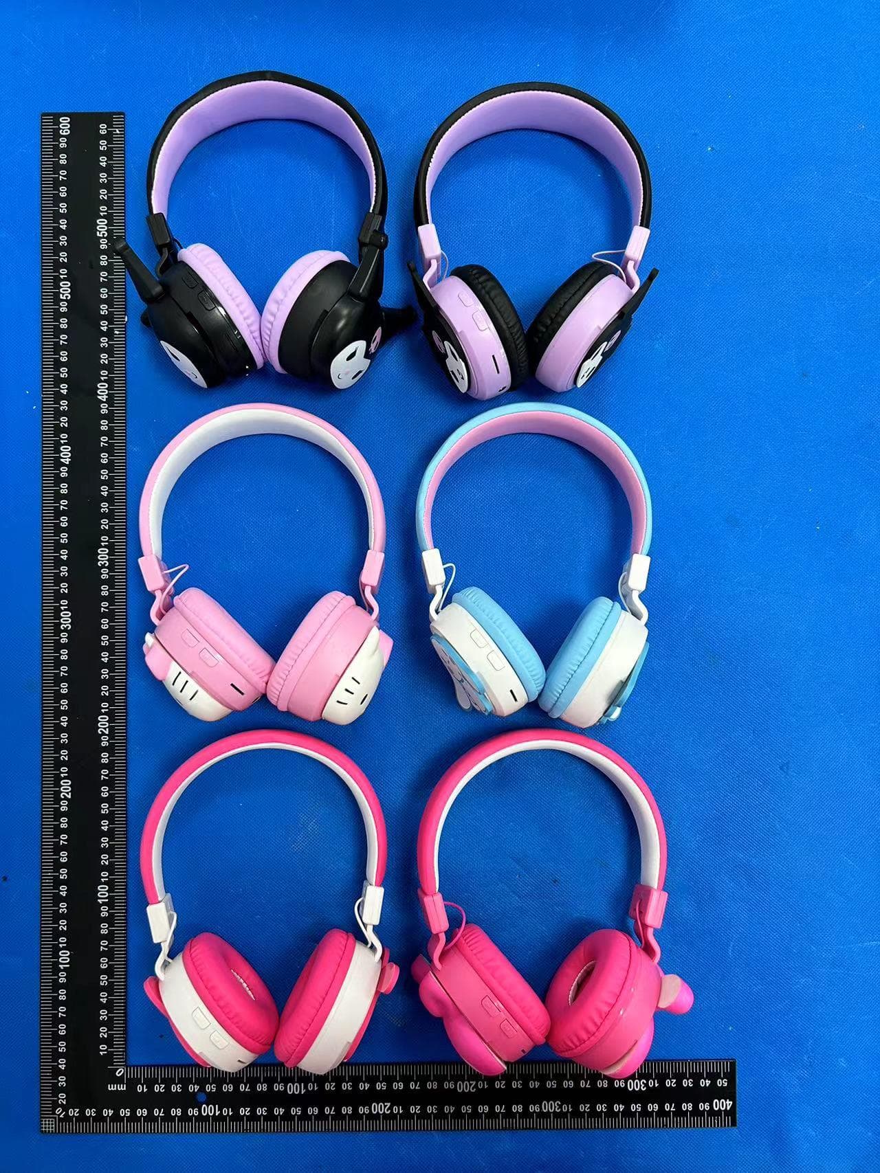
2AU75HKFA1-RH
Dec 17, 2023Bluetooth Headset
Equipment Class
DTS - Digital Transmission System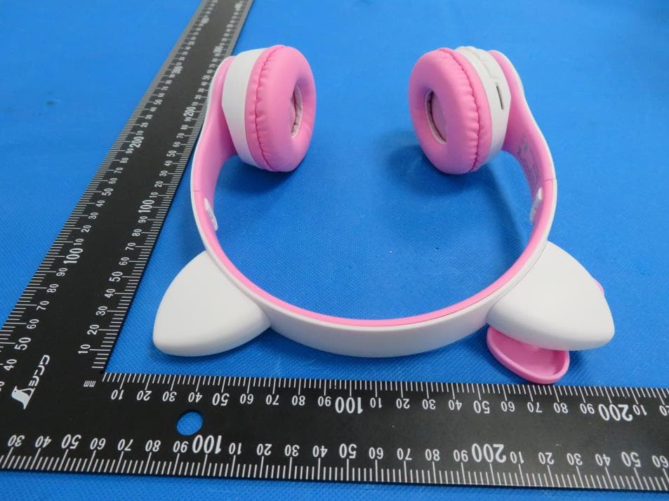
2AU75BTHP1-FB
Oct 16, 2023Bluetooth Headset
Equipment Class
DSS - Part 15 Spread Spectrum Transmitter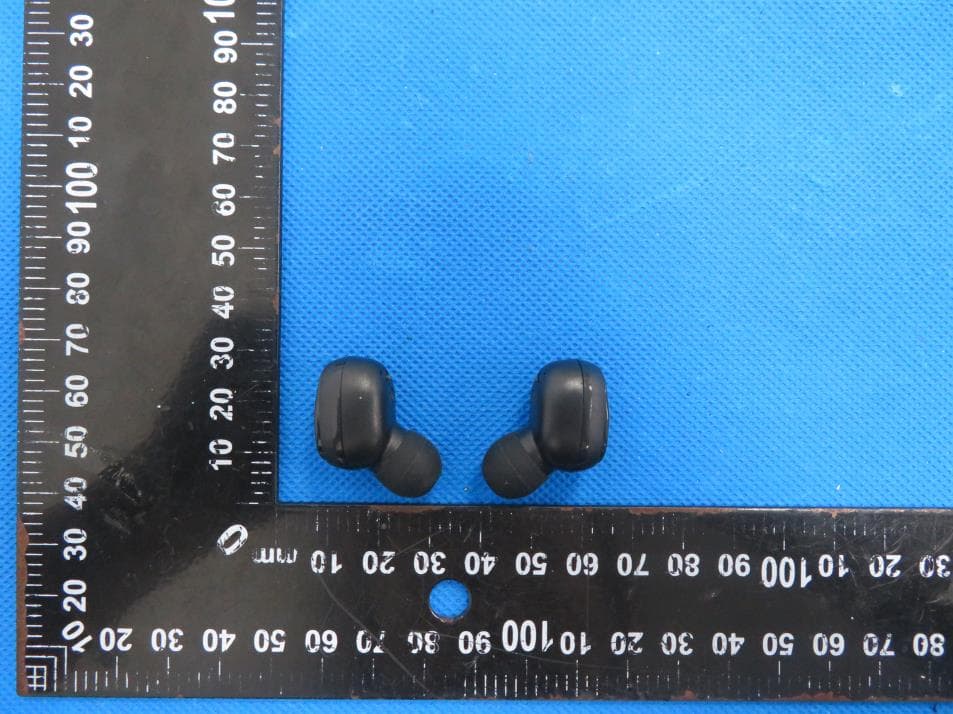
2AU75-ARTWS50
Jul 31, 2023TWS EARBUDS
Equipment Class
DSS - Part 15 Spread Spectrum Transmitter
2AU75-SHOWERSP
Jun 29, 2021bluetooth speaker
Equipment Class
DSS - Part 15 Spread Spectrum Transmitter
2AU75-FIBER
Jul 07, 2020Bluetooth Speaker
Equipment Class
DSS - Part 15 Spread Spectrum Transmitter