2AU79-SMM01NFC Reader rev 2.1
3DGence sp. z o.o.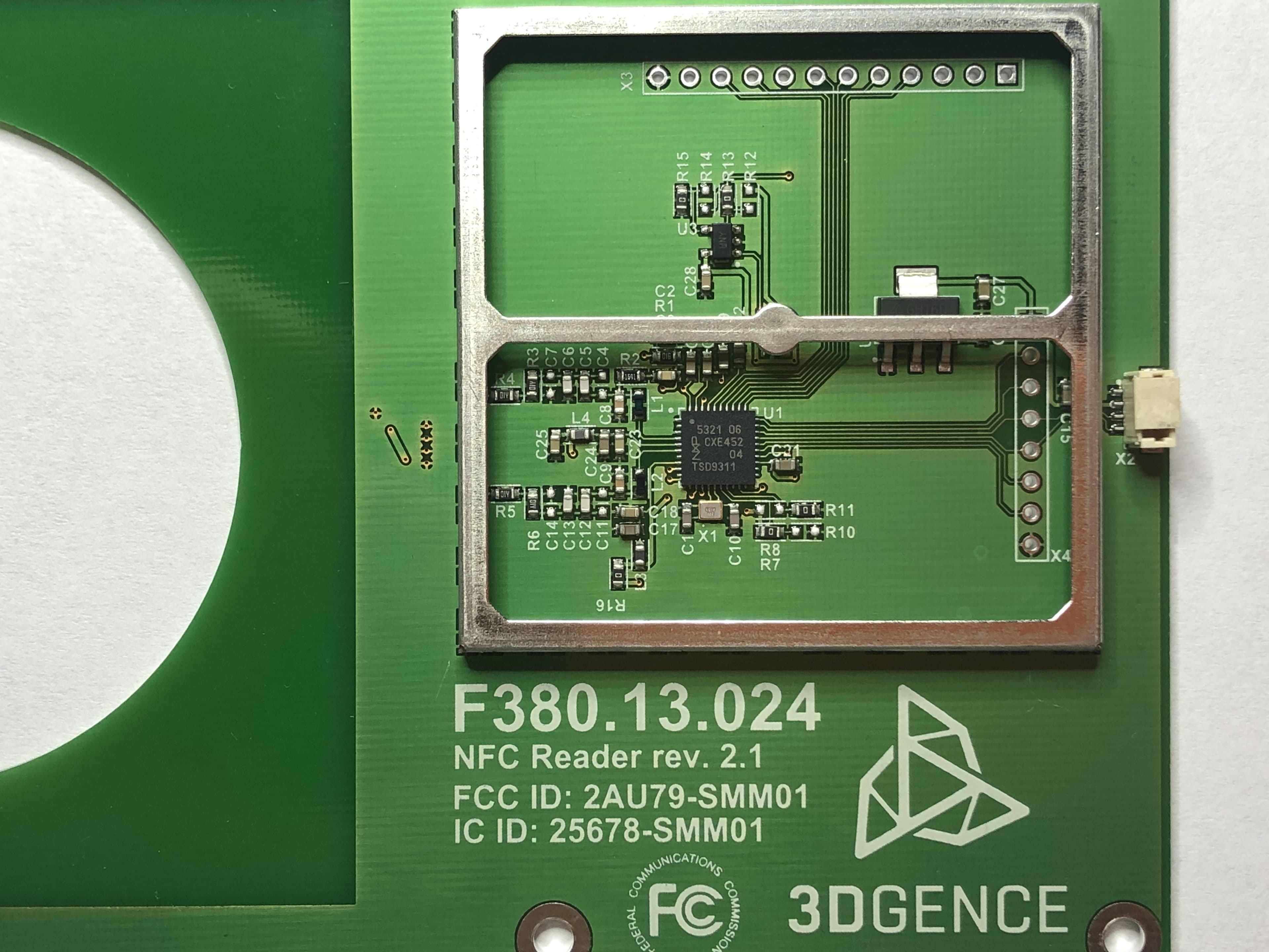
Click to zoom
Application Details
- Equipment Class
- DXX - Part 15 Low Power Communication Device Transmitter
- Date of Grant
- Jul 07, 2020
- Application Purpose
- Original Equipment
- Date of Application
- Jul 05, 2020
- Equipment Note
- NFC Reader rev 2.1
- Frequency Range
- 13.56000000 - 13.56000000
- Company
- 3DGence sp. z o.o.
- Country
- Poland
Documents & Files
Document Text
Text extracted from the exhibit documents filed with the FCC. Open a document above to read the original.
Users Manual
page 1 of 6 3DGence | Przyszowice Office | Graniczna 66, 44-178 Przyszowice, Poland www.3dgence.com Headquarters: 3DGence Sp. z o.o. | Mickiewicza 29, 40-085 Katowice, Poland KRS: 0000265431 | VAT-EU: PL6330009438 | REGON: 271077426 Share capital: 1.400.000 PLN NFC Reader User Manual rev. 1.2 Supplier's Declaration of Conformity 47 CFR § 2.1077 Compliance Information Unique Identifier: Trade name: NFC Reader rev 2.1, Model number: F380.13.024 FCC ID: 2AU79-SMM01 IC: 25678-SMM01 Responsible Party – U.S. Contact Information: 3DGence America, Inc. 1841 E.Levee Street 75207 Dallas, TX Telephone: +1.855.466.3813 FCC Compliance Statement: CAUTION: Changes or modifications not expressly approved could void your authority to use this equipment This device complies with Part 15 of the FCC Rules. Operation to the following two conditions: (1) This device may not cause harmful interference, and (2) this device must accept any interference received, including interference that may cause undesired operation NOTE: This equipment has been tested and found to comply with the limits for a Class A digital device, pursuant to part 15 of the FCC Rules. These limits are designed to provide reasonable protection against harmful interference when the equipment is operated in a commercial environment. This equipment generates, uses, and can radiate radio frequency energy and, if not installed and used in accordance with the instruction manual, may cause harmful interference to radio communications. Operation of this equipment in a residential area is likely to cause harmful interference in which case the user will be required to correct the interference at his own expense. INDUSTRY CANADA STATEMENT This device complies with Industry Canada license-exempt RSS standard(s). Operation is subject to the following two conditions: (1) this device may not cause interference, and (2) this device must accept any interference, including interference that may cause undesired operation of the device. Le présent appareil est conforme aux CNR d'Industrie Canada applicables aux appareils radio exempts de licence. L'exploitation est autorisée aux deux conditions suivantes : (1) l'appareil ne doit pas produire de brouillage, et (2) l'utilisateur de l'appareil doit accepter tout brouillage radioélectrique subi, même si le brouillage est susceptible d'en compromettre le fonctionnement. page 2 of 6 3DGence | Przyszowice Office | Graniczna 66, 44-178 Przyszowice, Poland www.3dgence.com Headquarters: 3DGence Sp. z o.o. | Mickiewicza 29, 40-085 Katowice, Poland KRS: 0000265431 | VAT-EU: PL6330009438 | REGON: 271077426 Share capital: 1.400.000 PLN NFC Reader User Manual rev. 1.2 NFC Reader User Manual 1. Overview The solution introduced by 3DGence Sp.z o.o. based on NFC technology aims to identify materials used in additive technology through manufacturing equipment. It consists of 2 parts, a reader placed in the additive manufacturing machine and Tags mounted on reels with thermoplastic material. Device works in NFC reader/writer (i. e. ISO/IEC 14443A/MIFARE Reader/Writer) mode which enables it to read/write information on dedicated NFC tags. The tags provided by 3DGence sp. z o.o. consists of a self-adhesive sticker, loop coil antenna and Mifare chip. The memory of the chip contains information about the material used in the additive manufacturing technology, such as: Type of material, producer, color, processing temperatures, remaining quantity etc. 2. Features • ISO/IEC 14443A/MIFARE Reader/Writer • Operating distance up to 50mm • Supported host interfaces o SPI interface o I 2 C interface o High-speed UART • 4.0 to 5.5 V power supply operating range • Compatible with 3DGence dedicated NFC Tag • FCC/UL certified module 3. Typical Application 4. Main connector pinout Pin Function Comment 1 GND Ground Pin 2 Vcc Power supply 3 SDA I 2 C clock 4 SCL I 2 C data 5. Applications • 3D Printers page 3 of 6 3DGence | Przyszowice Office | Graniczna 66, 44-178 Przyszowice, Poland www.3dgence.com Headquarters: 3DGence Sp. z o.o. | Mickiewicza 29, 40-085 Katowice, Poland KRS: 0000265431 | VAT-EU: PL6330009438 | REGON: 271077426 Share capital: 1.400.000 PLN NFC Reader User Manual rev. 1.2 6. Mounting guide Module has 6 holes with 3.2mm diameter to fit M3 screw. The pads around holes are not connected to ground on the PCB. The pads diameter is 6mm, make sure screw head is not bigger than 6mm. If it is, there is a risk of short circuit and inappropriate module functioning. If the module is meant to be attached to metal surface, there is a risk that antenna will be detuned. To prevent antenna detuning it is recommended to mount the module on non-metal surface, or apply at least 7mm spacer between the module and metal surface. page 4 of 6 3DGence | Przyszowice Office | Graniczna 66, 44-178 Przyszowice, Poland www.3dgence.com Headquarters: 3DGence Sp. z o.o. | Mickiewicza 29, 40-085 Katowice, Poland KRS: 0000265431 | VAT-EU: PL6330009438 | REGON: 271077426 Share capital: 1.400.000 PLN NFC Reader User Manual rev. 1.2 Due to ESD protection it is recommended to cover the module with non-metal housing as marked on the picture below. 7. Antenna specification • Dimensions: 84 x 84 mm • Antenna turns: 4 • Turns separation: 0.6 mm • Track width: 0.6 mm • Track height: 35 um • Frequency range capability: 13.56MHz ± 7 kHz. • Peak gain: N/A • Antenna Pattern: square 8. Programming guide Please refer to PN532 manuals for further information: • Datasheet: https://www.nxp.com/docs/en/nxp/data-sheets/PN532_C1.pdf • User manual: https://www.nxp.com/docs/en/user-guide/141520.pdf page 5 of 6 3DGence | Przyszowice Office | Graniczna 66, 44-178 Przyszowice, Poland www.3dgence.com Headquarters: 3DGence Sp. z o.o. | Mickiewicza 29, 40-085 Katowice, Poland KRS: 0000265431 | VAT-EU: PL6330009438 | REGON: 271077426 Share capital: 1.400.000 PLN NFC Reader User Manual rev. 1.2 9. Supported tag specification Module supports dedicated NFC tag with MIFARE 1K chip. Tag parameters: …
Text truncated - open the document above for the full version.
Cover Letter(s)
page 1 of 1 3DGence | Przyszowice Office | Graniczna 66, 44-178 Przyszowice, Poland www.3dgence.com Headquarters: 3DGence Sp. z o.o. | Mickiewicza 29, 40-085 Katowice, Poland KRS: 0000265431 | VAT-EU: PL6330009438 | REGON: 271077426 Share capital: 1.400.000 PLN Federal Communications Commission 7435 Oakland Mills Road Columbia MD 21046 Subject: Request for Confidentiality FCC ID: 2AU79-SMM01 To Whom It May Concern: Pursuant to the provisions of Sections 0.457 and 0.459 of the Commission’s rules (47 CFR §§ 0.457, 0.459), we are requesting the Commission to withhold the following attachments as confidential document from public disclosure indefinitely. Schematic Diagram Block Diagram Theory of Operation Antenna Specification Integration Manual The module is not for sale and the user manual integration instructions are internal confidential manufacturing documents. Above mentioned document contains detailed system and equipment description are considered as proprietary information in operation of the equipment. The public disclosure of above documents might be harmful to our company and would give competitor an unfair advantage in the market. In additional to above mentioned documents, pursuant to Public Notice DA 04-1705 of the Commission’s policy, in order to comply with the marketing regulations in 47 CFR §2.803 and the importation rules in 47 CFR §2.1204, while ensuring that business sensitive information remains confidential until the actual marketing of newly authorized devices. We are requesting the commission to grant short-term confidentiality request on the following attachments until 06/5/2020. Internal Photos Test Setup Photos User Manual It is our understanding that all measurement test reports, FCC ID label format and correspondent during certification review process cannot be granted as confidential documents and those information will be available for public review once the grant of equipment authorization is issued. Best Regards Krzysztof Wilk, Head of R&D 3DGence sp. z o.o 4/17/2020
Cover Letter(s)
Applicant/Grantee 3DGence, sp. z o.o. FCC ID: 2AU79-SMM01 Section 15.212 Modular Transmitters Request for Modular Approval Request for Limited Modular Approval Requirements EUT Conditions Comply (Y/N) Single Modular Approval Requirements 1 The radio elements of the modular transmitter must have their own shielding. The physical crystal and tuning capacitors may be located external to the shielded radio elements. Y 2 The modular transmitter must have buffered modulation/data inputs (if such inputs are provided) to ensure that the module will comply with Part 15 requirements under conditions of excessive data rates or over-modulation. Y 3 The modular transmitter must have its own power supply regulation. Y 4 The modular transmitter must comply with the antenna and transmission system requirements of Sections 15.203, 15.204(b) and 15.204(c). The antenna must either be permanently attached or employ a “unique” antenna coupler (at all connections between the module and the antenna, including the cable). The “professional installation” provision of Section 15.203 is not applicable to modules but can apply to limited modular approvals under paragraph (b) of this section. Y 5 The modular transmitter must be tested in a stand-alone configuration, i.e., the module must not be inside another device during testing for compliance with Part 15 requirements. Unless the transmitter module will be battery powered, it must comply with the AC line conducted requirements found in Section 15.207. AC or DC power lines and data input/output lines connected to the module must not contain ferrites, unless they will be marketed with the module (see Section 15.27(a)). The length of these lines shall be the length typical of actual use or, if that length is unknown, at least 10 centimeters to insure that there is no coupling between the case of the module and supporting Y equipment. Any accessories, peripherals, or support equipment connected to the module during testing shall be unmodified and commercially available (see Section 15.31(i)). 6 The modular transmitter must be equipped with either a permanently affixed label or must be capable of electronically displaying its FCC identification number. (A) If using a permanently affixed label, the modular transmitter must be labeled with its own FCC identification number, and, if the FCC identification number is not visible when the module is installed inside another device, then the outside of the device into which the module is installed must also display a label referring to the enclosed module. This exterior label can use wording such as the following: “Contains Transmitter Module FCC ID: XYZMODEL1” or “Contains FCC ID: XYZMODEL1.” Any similar wording that expresses the same meaning may be used. The Grantee may either provide such a label, an example of which must be included in the application for equipment authorization, or, must provide adequate instructions along with the module which explain this requirement. In the latter case, a copy of these instructions must be included in the application for equipment authorization. (B) If the modular transmitter uses an electronic display of the FCC identification number, the information must be readily accessible and visible on the modular transmitter or on the device in which it is installed. If the module is installed inside another device, then the outside of the device into which the module is installed must display a label referring to the enclosed module. This exterior label can use wording such as the following: “Contains FCC certified transmitter module(s).” Any similar wording that expresses the same meaning may be used. The user manual must include instructions on how to access the electronic display. A copy of these instructions must be included in the application for equipment authorization. Y 7 The modular transmitter must comply with any specific rules or operating requirements that ordinarily apply to a complete transmitter and the manufacturer must provide adequate instructions along with the module to explain any such requirements. A copy of these instructions must be included in the application for equipment authorization. Y 8 The modular transmitter must comply with any applicable RF exposure requirements in its final configuration. Y A limited modular approval may be granted for single or split modular transmitters that do not comply with all of the above requirements, e.g., shielding, minimum signaling amplitude, buffered modulation/data inputs, or power supply regulation, if the manufacturer can demonstrate by alternative means in the application for equipment authorization that the modular transmitter meets all the applicable Part 15 requirements under the operating conditions in which the transmitter will be used. Limited modular approval also may be granted in those instances where compliance with RF exposure rules is demonstrated only for particular product configurations. The applicant for certification must state how control of the end product into which the module will be installed will be maintained such that full compliance of the end product is always ensured.
Test Report
NVLAP Lab code: 200246-0 CERTIFICATION TEST REPORT Report Number: R13104595-E1 Applicant : 3DGence Sp. Z o.o Mickiewicza 29, 40-085 Katowice Poland Model : F380.13.024 FCC ID : 2AU79-SMM01 IC : 25678-SMM01 EUT Description : NFC reader rev. 1.1 Test Standard(s) : FCC 47 CFR PART 15 SUBPART C ISED CANADA RSS-210 ISSUE 10 Date Of Issue: April 03, 2020 Prepared by: UL LLC 12 Laboratory Dr. Research Triangle Park, NC 27709 U.S.A. TEL: (919) 549-1400 REPORT NO: R13104595-E1 DATE: 2020-04-03 FCC ID: 2AU79-SMM01 IC: 25678-SMM01 Page 2 of 34 UL LLC FORM NO: CCSUP4701I 12 Laboratory Dr., RTP, NC 27709; USA TEL:(919) 549-1400 This report shall not be reproduced except in full, without the written approval of UL LLC REVISION HISTORY Rev. Issue Date Revisions Revised By 1 2020-04-03 Initial Issue Brian T. Kiewra REPORT NO: R13104595-E1 DATE: 2020-04-03 FCC ID: 2AU79-SMM01 IC: 25678-SMM01 Page 3 of 34 UL LLC FORM NO: CCSUP4701I 12 Laboratory Dr., RTP, NC 27709; USA TEL:(919) 549-1400 This report shall not be reproduced except in full, without the written approval of UL LLC TABLE OF CONTENTS REVISION HISTORY .................................................................................................................... 2 TABLE OF CONTENTS ............................................................................................................... 3 1. ATTESTATION OF TEST RESULTS .................................................................................... 4 2. TEST METHODOLOGY ........................................................................................................ 5 3. FACILITIES AND ACCREDITATION .................................................................................... 5 4. CALIBRATION AND UNCERTAINTY .................................................................................. 6 MEASURING INSTRUMENT CALIBRATION ................................................................ 6 SAMPLE CALCULATION ............................................................................................... 6 MEASUREMENT UNCERTAINTY ................................................................................. 6 5. EQUIPMENT UNDER TEST ................................................................................................. 7 DESCRIPTION OF EUT ................................................................................................. 7 MAXIMUM FIELD STRENGTH ...................................................................................... 7 SOFTWARE AND FIRMWARE ...................................................................................... 7 WORST-CASE CONFIGURATION AND MODE ............................................................ 7 DESCRIPTION OF TEST SETUP .................................................................................. 8 6. TEST AND MEASUREMENT EQUIPMENT ......................................................................... 9 7. OCCUPIED BANDWIDTH ................................................................................................... 11 WITHOUT TAG ............................................................................................................ 11 WITH TAG .................................................................................................................... 13 8. RADIATED EMISSION TEST RESULTS ............................................................................ 15 LIMITS AND PROCEDURE ......................................................................................... 15 FUNDAMENTAL AND SPURIOUS EMISSIONS (0.15 - 30 MHz) ............................... 17 WITHOUT TAG ..................................................................................................... 17 WITH TAG ............................................................................................................. 20 TX SPURIOUS EMISSION 30 TO 1000 MHz .............................................................. 23 WITHOUT TAG ..................................................................................................... 23 WITH TAG ............................................................................................................. 25 9. FREQUENCY STABILITY ................................................................................................... 27 WITHOUT TAG ............................................................................................................ 27 WITH TAG .................................................................................................................... 28 10. AC MAINS LINE CONDUCTED EMISSIONS ................................................................. 29 WITHOUT TAG ......................................................................................................... 30 WITH TAG ................................................................................................................ 32 11. SETUP PHOTOS ............................................................................................................. 34 END OF TEST REPORT ............................................................................................................ 34 REPORT NO: R13104595-E1 DATE: 2020-04-03 FCC ID: 2AU79-SMM01 IC: 25678-SMM01 Page 4 of 34 UL LLC FORM NO: CCSUP4701I 12 Laboratory Dr., RTP, NC 27709; USA TEL:(919) 549-1400 This report shall not be reproduced except in full, without the written approval of UL LLC 1. ATTESTATION OF TEST RESULTS COMPANY NAME: 3DGence Sp. Z o.o Mickiewicza 29, 40-085 Katowice Poland EUT DESCRIPTION: NFC reader rev. 1.1 MODEL: F380.13.024 SERIAL NUMBER: Non-Serialized SAMPLE RECEIVED: 2019-12-05 DATE TESTED: 2020-03-02 to 2020-03-03 APPLICABLE STANDARDS STANDARD TEST RESULTS FCC PART 15 SUBPART C Compliant ISED RSS-210 Issue 10, Annex B.6 Compliant ISED RSS-GEN Issue 5 Compliant UL LLC tested the above equipment in accordance with the requirements set forth in the above standards. The test res…
Text truncated - open the document above for the full version.
Test Setup Photos
NVLAP Lab code: 200246-0 SETUP PHOTOS EXHIBIT Report Number: R13104595-EP1 Applicant : 3DGence Sp. Z o.o Mickiewicza 29, 40-085 Katowice Poland Model : F380.13.024 FCC ID : 2AU79-SMM01 IC : 25678-SMM01 EUT Description : NFC reader rev. 1.1 Test Standard(s) : FCC 47 CFR PART 15 SUBPART C ISED CANADA RSS-210 ISSUE 10 Date Of Issue: April 03, 2020 Prepared by: UL LLC 12 Laboratory Dr. Research Triangle Park, NC 27709 U.S.A. TEL: (919) 549-1400 REPORT NO: R13104595-EP1 DATE: 2020-04-03 FCC ID: 2AU79-SMM01 IC: 25678-SMM01 Page 2 of 11 UL LLC FORM NO: CCSUP4701I 12 Laboratory Dr., RTP, NC 27709; USA TEL:(919) 549-1400 This report shall not be reproduced except in full, without the written approval of UL LLC REVISION HISTORY Rev. Issue Date Revisions Revised By 1 2020-04-03 Initial Issue Cristian Melara REPORT NO: R13104595-EP1 DATE: 2020-04-03 FCC ID: 2AU79-SMM01 IC: 25678-SMM01 Page 3 of 11 UL LLC FORM NO: CCSUP4701I 12 Laboratory Dr., RTP, NC 27709; USA TEL:(919) 549-1400 This report shall not be reproduced except in full, without the written approval of UL LLC TABLE OF CONTENTS REVISION HISTORY .................................................................................................................... 2 TABLE OF CONTENTS ............................................................................................................... 3 1. SETUP DIAGRAM ................................................................................................................. 4 2. SETUP PHOTOS ................................................................................................................... 5 END OF TEST REPORT ............................................................................................................ 11 REPORT NO: R13104595-EP1 DATE: 2020-04-03 FCC ID: 2AU79-SMM01 IC: 25678-SMM01 Page 4 of 11 UL LLC FORM NO: CCSUP4701I 12 Laboratory Dr., RTP, NC 27709; USA TEL:(919) 549-1400 This report shall not be reproduced except in full, without the written approval of UL LLC 1. SETUP DIAGRAM REPORT NO: R13104595-EP1 DATE: 2020-04-03 FCC ID: 2AU79-SMM01 IC: 25678-SMM01 Page 5 of 11 UL LLC FORM NO: CCSUP4701I 12 Laboratory Dr., RTP, NC 27709; USA TEL:(919) 549-1400 This report shall not be reproduced except in full, without the written approval of UL LLC 2. SETUP PHOTOS OCCUPIED BANDWIDTH (WITHOUT/WITH TAG) REPORT NO: R13104595-EP1 DATE: 2020-04-03 FCC ID: 2AU79-SMM01 IC: 25678-SMM01 Page 6 of 11 UL LLC FORM NO: CCSUP4701I 12 Laboratory Dr., RTP, NC 27709; USA TEL:(919) 549-1400 This report shall not be reproduced except in full, without the written approval of UL LLC RADIATED EMISSIONS SETUP RADIATED EMISSIONS <1GHz (WITHOUT TAG) REPORT NO: R13104595-EP1 DATE: 2020-04-03 FCC ID: 2AU79-SMM01 IC: 25678-SMM01 Page 7 of 11 UL LLC FORM NO: CCSUP4701I 12 Laboratory Dr., RTP, NC 27709; USA TEL:(919) 549-1400 This report shall not be reproduced except in full, without the written approval of UL LLC RADIATED EMISSIONS <1GHz (WITH TAG) REPORT NO: R13104595-EP1 DATE: 2020-04-03 FCC ID: 2AU79-SMM01 IC: 25678-SMM01 Page 8 of 11 UL LLC FORM NO: CCSUP4701I 12 Laboratory Dr., RTP, NC 27709; USA TEL:(919) 549-1400 This report shall not be reproduced except in full, without the written approval of UL LLC X-AXIS PHOTO Y-AXIS PHOTO REPORT NO: R13104595-EP1 DATE: 2020-04-03 FCC ID: 2AU79-SMM01 IC: 25678-SMM01 Page 9 of 11 UL LLC FORM NO: CCSUP4701I 12 Laboratory Dr., RTP, NC 27709; USA TEL:(919) 549-1400 This report shall not be reproduced except in full, without the written approval of UL LLC Z-AXIS PHOTO REPORT NO: R13104595-EP1 DATE: 2020-04-03 FCC ID: 2AU79-SMM01 IC: 25678-SMM01 Page 10 of 11 UL LLC FORM NO: CCSUP4701I 12 Laboratory Dr., RTP, NC 27709; USA TEL:(919) 549-1400 This report shall not be reproduced except in full, without the written approval of UL LLC AC MAINS LINE CONDUCTED EMISSION WITHOUT TAG REPORT NO: R13104595-EP1 DATE: 2020-04-03 FCC ID: 2AU79-SMM01 IC: 25678-SMM01 Page 11 of 11 UL LLC FORM NO: CCSUP4701I 12 Laboratory Dr., RTP, NC 27709; USA TEL:(919) 549-1400 This report shall not be reproduced except in full, without the written approval of UL LLC END OF TEST REPORT WITH TAG
Contact Information
Applicant
Krzysztof Wilk(Mr.)
Test Firm
UL LLCRick Titus
Technical Specifications
| # | Rule Parts | Frequency Range | Power Output |
|---|---|---|---|
| 1 | 15C | 13.56 MHz - 13.56 MHz | - |