2AU7J-SMARTMETERSmart Meter
GoodWe Technologies Co., Ltd.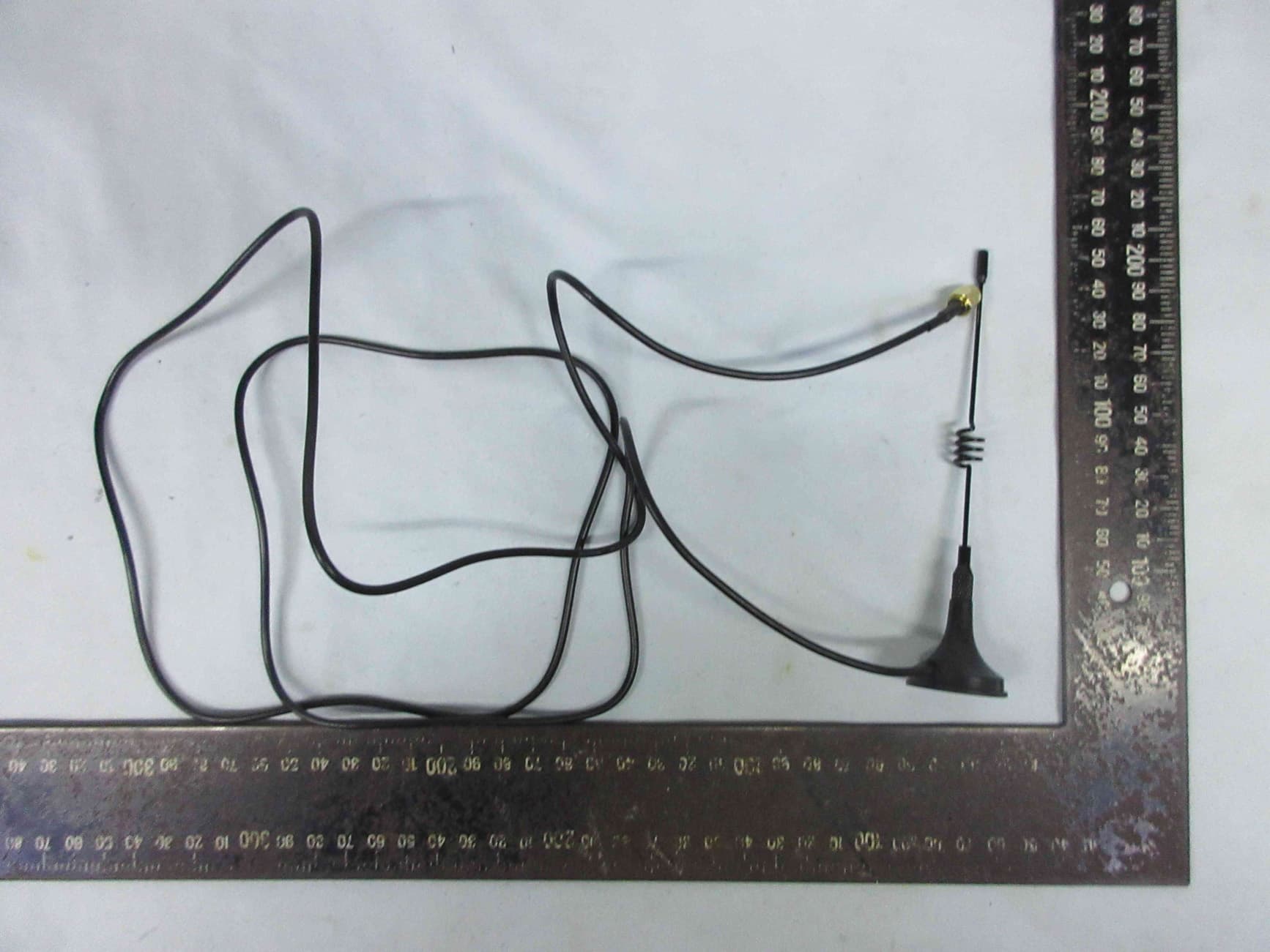
Click to zoom
Application Details
- Equipment Class
- DTS - Digital Transmission System
- Date of Grant
- Aug 15, 2022
- Application Purpose
- Original Equipment
- Date of Application
- Aug 15, 2022
- Equipment Note
- Smart Meter
- Frequency Range
- 2412.00000000 - 2462.00000000
- Country
- China
Documents & Files
Document Text
Text extracted from the exhibit documents filed with the FCC. Open a document above to read the original.
Users Manual
V1.0-2022-05-30 (GMK120 | GMK140 | GM330) Quick Installation Guide Smart Meter 1 • Make sure that the device is powered off before any operations. • Ensure the cables are connected tightly, securely, and correctly. Inappropriate wiring may cause poor contact or damage the device. • Additional circuit breakers are recommended on the voltage input side to avoid personal injury or device damage. • Specification of the protective fuse should be 0.5A. • In areas at risk of lightning, if the input cable of the device exceeds 10m (33ft), you are recommended to use an external lightning protection device. If the communication cables are wired with grounded metal conduits, the lightning protection device is not necessary. • Strictly follow the National Electrical Code, ANSI/NFPA 70, and Canadian Electrical Code C22.1 during operations. • The information in this quick installation guide is subject to change due to product updates or other reasons. All descriptions here are for guidance only. • Before installations, read through the quick installation guide. • All operations should be performed by trained and knowledgeable technicians who are familiar with local standards and safety regulations. • Check the deliverables for correct model, complete contents, and intact appearance. Contact the manufacturer if any damage is found or any component is missing. • Strictly follow the installation, operation, and configuration instructions in this guide and user manual. The manufacturer shall not be liable for equipment damage or personal injury if you do not follow the instructions. For more warranty details, please visit https://en.goodwe.com/warranty. 01 Safety Precautions General Disclaimer Safety Disclaimer WARINING Check before Power-on No.Check Item 1 The product is firmly installed at a clean place that is well-ventilated and easy- to-operate. 2 The input power cables, CT Cables, and communication cables are connected correctly and securely. 3Cable ties are intact, routed properly and evenly. 2 Storage RF exposure warning Federal Communications Commission (FCC) Interference Statement If the equipment is not to be installed or used immediately, please ensure that the storage environment meets the following requirements: Do not unpack the outer package or throw the desiccant away. Store the equipment in a clean place. Make sure the temperature and humidity are appropriate and no condensation. If the smart meter has been long term stored, it should be checked by professionals before being put into use. This equipment complies with FCC radiation exposure limits set forth for an uncontrolled environment. This equipment must be installed and operated in accordance with provided instructions and the antenna(s) used for this transmitter must be installed to provide a separation distance of at least 20 cm from all persons and must not be collocated or operating in conjunction with any other antenna or transmitter. This equipment has been tested and found to comply with the limits for a Class B digital device, pursuant to Part 15 of the FCC Rules. These limits are designed to provide reasonable protection against harmful interference in a residential installation. This equipment generate, uses and can radiate radio frequency energy and, if not installed and used in accordance with the instructions, may cause harmful interference to radio communications. However, there is no guarantee that interference will not occur in a particular installation. If this equipment does cause harmful interference to radio or television reception, which can be determined by turning the equipment off and on, the user is encouraged to try to correct the interference by one of the following measures: • Reorient or relocate the receiving antenna. • Increase the separation between the equipment and receiver. • Connect the equipment into an outlet on a circuit different from that to which the receiver is connected. • Consult the dealer or an experienced radio/TV technician for help. This device complies with Part 15 of the FCC Rules. Operation is subject to the following two conditions: 1. This device may not cause harmful interference. 2. this device must accept any interference received, including interference that may cause undesired operation. FCC Caution: Any changes or modifications not expressly approved by the party responsible for compliance could void the user's authority to operate this equipment. 3 02 Product Introduction GMK120 Top view Front View L3(Reserved) CT3+(Reserved)CT3-(Reserved) Indicators Reset Button Bottom view Side view Federal Communications Commission (FCC) Interference Statement 4 GMK140 Front View L3(Reserved) Indicators Reset Button Top viewBottom view Side view CT3+(Reserved) CT3+(Reserved) CT3-(Reserved) CT3-(Reserved) 5 GM330 Front View Indicators Reset Button Top view Bottom view Side view 6 CT Waterproof box CT direction:House-->Grid 7 GMK120 03 Wiring System NOTE • Recommended cross-sectional area of the smart meter input power cable: 1mm 2 (18AWG). • CT direction: House-->Grid. • You are recommended to add fuses with a rated current of 0.5A to L1and L2 on the meter side. • To ensure the correctness of the monitoring data, connect CT1 to L1, CT2 to L2. Also, the N wire, L1, and L2 need to be connected between the loads and the utility meter. Hybrid Inverter Loads Fuse 0.5A Household Meter Utility Grid 8 GMK140 NOTE • Recommended cross-sectional area of the smart meter input power cable: 1mm 2 (18AWG). • CT direction: House-->Grid. • You are recommended to add fuses with a rated current of 0.5A to L1and L2 on the meter side. • To ensure the correctness of the monitoring data, connect CT1, CT3 to L1, CT2, CT4 to L2. Also, the N wire, L1, and L2 need to be connected between the loads and the utility meter. AC-Coupled Inverter Grid-Tied PV Inverter Loads PV Fuse 0.5A Household Meter Utility Grid 9 GM330 NOTE • Recommended cross-sectional area of the smart meter input power cable: 1mm 2 (18AWG). • Cus…
Text truncated - open the document above for the full version.
Cover Letter(s)
COMPANY LETTERHEAD 6/8/2022 Nemko North America, Inc. 303 River Road Ottawa, Ontario, Canada K1V 1H2 AUTHORITY TO ACT AS AGENT - FCC On our behalf, I appoint GoodWe Technologies Co.,Ltd, to act as our agent in the preparation of this application for equipment certification. I certify that submitted documents properly describe the device or system for which equipment certification is sought. I also certify that each unit manufactured, imported or marketed, as defined in FCC regulations will have affixed to it a label identical to that submitted for approval with this application. In signing this letter, Applicant certifies that neither the applicant nor any party to the application is not subject to a denial of Federal benefits, that include FCC benefits, pursuant to Section 5301 of the Anti-Drug Abuse Act of 1988, 21 U.S.C. § 862 because of a conviction for possession or distribution of a controlled substance. See 47 CFR 1.2002(b) for the definition of a "party" for these purposes. For instances where our authorized agent signs the application for certification on our behalf, I acknowledge that all responsibility for complying with the terms and conditions for certification, as specified by Nemko North America Inc., still resides still resides with us. Sincerely, Printed name: wangchenghu
Cover Letter(s)
GoodWe Technologies Co.,Ltd Declaration on model difference Product name: Smart Meter Model: GMK121;GMK141 To whom it may concern, We (GoodWe Technologies Co.,Ltd) ; hereby declare that these models have the same RF module and antenna. are all the same in RF electrical, and the differences are as follows: Respectfully, Date: 2022/06/13 Name: Wangchenghu Function: Manager Signature: Product Type Model Difference Smart Meter GMK121 GMK141 supports 4 pcs of external CTs(200A); GMK121 supports 2 pcs of external CTs(200A); GMK141
Cover Letter(s)
COMPANY LETTERHEAD 6/8/2022 Nemko North America, Inc. 303 River Road Ottawa, Ontario, Canada K1V 1H2 REQUEST FOR CONFIDENTIALITY - FCC FCC ID: 2AU7J-SMARTMETER Pursuant to Sections 0.457(d)(1)(ii) and 0.459 of the Commission’s Rules and FCC Guidance document 726920, we hereby request confidential treatment of information accompanying this application as outlined below: PERMANENT LONG-TERM CONFIDENTIALITY: Schematics Bill of Materials/Parts List Block Diagrams Theory of Operation SHORT TERM CONFIDENTIALITY FOR A PERIOD OF 180 DAYS (Note: you can list up to 180 days, but should not go past the date you start product marketing/sale): Internal Photos External Photos User Manual Test Set-up Photographs When the device is marketed before the requested number of days listed above, the grantee will inform the TCB to release the Short-Term Confidentiality information withheld on the FCC equipment authorization website. The above information contains trade secrets and proprietary information not customarily released to the public. The public disclosure of this information might be harmful to the applicant and provide unjustified benefits to its competitors. The Applicant understands that pursuant to Rule 0.457(d)(1)(ii), disclosure of this Application and all accompanying materials will not be made before the date of the Grant for this Application. Sincerely, Signed: Printed name: wangchenghu Title: Manager
External Photos
Page 1 of 4 Audix Technology (Wujiang )Co., Ltd. EMC Dept. Figure 1 General Appearance (Front View) Figure 2 General Appearance (Front View) Page 2 of 4 Audix Technology (Wujiang )Co., Ltd. EMC Dept. Figure 3 General Appearance (Back View) Figure 4 General Appearance (Side View) Page 3 of 4 Audix Technology (Wujiang )Co., Ltd. EMC Dept. Figure 5 General Appearance (Side View) Figure 6 General Appearance (Side View) Page 4 of 4 Audix Technology (Wujiang )Co., Ltd. EMC Dept. Figure 7 General Appearance (Side View) Figure 8 Antenna
ID Label/Location Info
标签尺寸标签位置 58.8m 31.6m
Internal Photos
Page 1 of 6 Audix Technology (Wujiang )Co., Ltd. EMC Dept. Figure 1 Internal View (Cover Removed Figure 2 PCB Board (Component Side) Page 2 of 6 Audix Technology (Wujiang )Co., Ltd. EMC Dept. Figure 3 PCB Board (Solder Side) Figure 4 PCB Board (Component Side) Page 3 of 6 Audix Technology (Wujiang )Co., Ltd. EMC Dept. Figure 5 PCB Board (Solder Side) Figure 6 PCB Board (Crystal Oscillator) Page 4 of 6 Audix Technology (Wujiang )Co., Ltd. EMC Dept. Figure 7 PCB Board (Crystal Oscillator) Figure 8 PCB Board (Component Side) Page 5 of 6 Audix Technology (Wujiang )Co., Ltd. EMC Dept. Figure 9 PCB Board (Without Shielding) Figure 10 PCB Board (Solder Side) Page 6 of 6 Audix Technology (Wujiang )Co., Ltd. EMC Dept. Figure 11 PCB Board (Crystal Oscillator) Figure 12 PCB Board (Crystal Oscillator)
RF Exposure Info
FCC ID: 2AU7J-SMARTMETER Page 1 of 8 Audix Technology (Wujiang )Co., Ltd. EMC Dept. Report No.: ACWE-F2204027 APPLICATION FOR CERTIFICATION On Behalf of GoodWe Technologies Co., Ltd. Smart Meter Model No. : (1)GMK121 (2)GMK141 Brand : GOODWE FCC ID : 2AU7J-SMARTMETER Prepared for GoodWe Technologies Co., Ltd. No.90 Zijin Rd., New District, Suzhou, 215011, China Prepared by Audix Technology (Wujiang) Co., Ltd. EMC Dept. No. 1289 Jiangxing East Road, the Part of Wujiang Economic Development Zone Jiangsu China 215200 Tel : +86-512-63403993 Fax :+86-512-63403339 Report No. : ACWE-F2204027 Date of Test : Apr.03, 2022 Date of Report : Apr.24, 2022 FCC ID: 2AU7J-SMARTMETER Page 2 of 8 Audix Technology (Wujiang )Co., Ltd. EMC Dept. Report No.: ACWE-F2204027 TABLE OF CONTENTS Description Page TEST REPORT CERTIFICATION ....................................................................................................... 4 1. DESCRIPTION OF VERSION .................................................................................................... 4 2. GENERAL INFORMATION ....................................................................................................... 5 2.1. Description of Device (EUT) .................................................................................................................. 5 2.2. Antenna Information ............................................................................................................................... 6 2.3. EUT Specification Assessed in Current Report ...................................................................................... 6 2.4. Description of Test Facility .................................................................................................................... 6 2.5. Measurement Uncertainty ....................................................................................................................... 6 3. SUMMARY OF STADARDS AND RESULTS .......................................................................... 7 3.1. Specification Limits ................................................................................................................................ 7 3.2. MPE Calculator Method ......................................................................................................................... 7 3.3. Calculated Result .................................................................................................................................... 8 FCC ID: 2AU7J-SMARTMETER Page 3 of 8 Audix Technology (Wujiang )Co., Ltd. EMC Dept. Report No.: ACWE-F2204027 TEST REPORT CERTIFICATION Applicant : GoodWe Technologies Co., Ltd. Manufacturer : GoodWe Technologies Co., Ltd. EUT Description : Smart Meter FCC ID : 2AU7J-SMARTMETER (A) Model No. : (1)GMK121 (2)GMK141 (B) Brand : GOODWE (C) Test Voltage : AC 120V/60Hz The measurement results are contained in this test report and Audix Technology (Wujiang) Co., Ltd. EMC Dept. is assumed full responsibility for the accuracy and completeness of these measurements. Also, this test report shows that the EUT to be technically compliant with the FCC limits. This test report applies to above tested sample only. This test report shall not be reproduced in part without written approval of Audix Technology (Wujiang) Co., Ltd. EMC Dept. Date of Test: Apr.03, 2022 Date of Report: Apr.24, 2022 Prepared by : (Emma Hu/Assistant Administrator) Approved & Authorized Signer : (Ken Lu/Vice General Manager) FCC ID: 2AU7J-SMARTMETER Page 4 of 8 Audix Technology (Wujiang )Co., Ltd. EMC Dept. Report No.: ACWE-F2204027 1. DESCRIPTION OF VERSION Edition No. Date of Rev. Summary Report No. 0 Apr.24, 2022 Original Report. ACWE-F2204027 FCC ID: 2AU7J-SMARTMETER Page 5 of 8 Audix Technology (Wujiang )Co., Ltd. EMC Dept. Report No.: ACWE-F2204027 2. GENERAL INFORMATION 2.1. Description of Device (EUT) Description : Smart Meter Model No. : (1)GMK121 (2)GMK141 Remark: The difference of the models is for sales market. Test Model : GMK141 FCC ID : 2AU7J-SMARTMETER Brand : GOODWE Applicant : GoodWe Technologies Co., Ltd. No.90 Zijin Rd., New District, Suzhou, 215011, China Manufacturer : GoodWe Technologies Co., Ltd. No.90 Zijin Rd., New District, Suzhou, 215011, China Date of Receipt of Sample : Apr.02, 2022 Date of Test : Apr.03, 2022 FCC ID: 2AU7J-SMARTMETER Page 6 of 8 Audix Technology (Wujiang )Co., Ltd. EMC Dept. Report No.: ACWE-F2204027 2.2. Antenna Information Antenna Type Frequency(MHz) Gain(dBi) Sucker Antenna 2400-2500 2.4 2.3. EUT Specification Assessed in Current Report Mode Fundamental Range (MHz) Channel Number Modulation 802.11b 2412-2462 11 DSSS 802.11g OFDM 802.11n-HT20 802.11n-HT40 2422-2452 9 2.4. Description of Test Facility Name of Firm : Audix Technology (Wujiang) Co., Ltd. EMC Dept. Site Location : No. 1289 Jiangxing East Road, the Eastern Part of Wujiang Economic Development Zone Jiangsu China 215200 Test Facilities : RF Fully Chamber NVLAP Lab Code : 200786-0 Valid until on Sep.30, 2022 (NVLAP is a signatory member of ILAC MRA) Remark: This report shall not be imply endorsement, certification or approval by NVLAP, NIST, or any agency of the U.S. Federal Government. 2.5. Measurement Uncertainty Test Item Uncertainty Maximum Peak Output Power 0.12dB Remark: Uncertainty = ku c (y) FCC ID: 2AU7J-SMARTMETER Page 7 of 8 Audix Technology (Wujiang )Co., Ltd. EMC Dept. Report No.: ACWE-F2204027 3. SUMMARY OF STADARDS AND RESULTS 3.1. Specification Limits According to FCC CFR 47 §1.1310, the criteria listed in the following table shall be used to evaluate the environmental impact of human exposure to radio frequency (RF) radiation as specified in 1.1307(b). Limits for Maximum Permissible Exposure NOTE: General population/uncontrolled exposures apply in situations in which the general public may be exposed, or in which persons that are exposed as a consequence of their employment may not be fully aware of the potential for exposure or can not exerc…
Text truncated - open the document above for the full version.
Test Report
FCC ID: 2AU7J-SMARTMETER Page 1 of 123 Audix Technology (Wujiang )Co., Ltd. EMC Dept. Report No.: ACWE-F2204020 APPLICATION FOR CERTIFICATION On Behalf of GoodWe Technologies Co., Ltd. Smart Meterer Model No. : (1)GMK121 (2)GMK141 Brand : GOODWE FCC ID : 2AU7J-SMARTMETER Prepared for GoodWe Technologies Co., Ltd. No.90 Zijin Rd., New District, Suzhou, 215011, China Prepared by Audix Technology (Wujiang) Co., Ltd. EMC Dept. No. 1289 Jiangxing East Road, the Part of Wujiang Economic Development Zone Jiangsu China 215200 Tel : +86-512-63403993 Fax :+86-512-63403339 Report No. : ACWE-F2204020 Date of Test : Apr.03~08, 2022 Date of Report : Apr.24, 2022 FCC ID: 2AU7J-SMARTMETER Page 2 of 123 Audix Technology (Wujiang )Co., Ltd. EMC Dept. Report No.: ACWE-F2204020 TABLE OF CONTENTS Description Page TEST REPORT CERTIFICATION ....................................................................................................... 4 1. DESCRIPTION OF VERSION .................................................................................................... 4 2. SUMMARY OF MEASUREMENTS AND RESULTS ............................................................. 5 3. GENERAL INFORMATION ....................................................................................................... 6 3.1. Description of Device (EUT) .................................................................................................................. 6 3.2. Antenna Information ............................................................................................................................... 7 3.3. EUT Specification Assessed in Current Report ...................................................................................... 7 3.4. Duty Cycle .............................................................................................................................................. 7 3.5. Tested Supporting System Details (AE) ................................................................................................. 7 3.6. Description of Test Facility .................................................................................................................... 8 3.7. Measurement Uncertainty ....................................................................................................................... 8 4. CONDUCTED EMISSION MEASUREMET ............................................................................ 9 4.1. Test Equipment ....................................................................................................................................... 9 4.2. Block Diagram of Test Setup .................................................................................................................. 9 4.3. Power line Conducted Emission Limit ................................................................................................... 9 4.4. Test Procedure ...................................................................................................................................... 10 4.5. Conducted Emission Measurement Results .......................................................................................... 11 5. RADIATED EMISSION MEASUREMENT ............................................................................ 14 5.1. Test Equipment ..................................................................................................................................... 14 5.2. Block Diagram of Test Setup ................................................................................................................ 14 5.3. Radiated Emission Limits ..................................................................................................................... 16 5.4. Test Procedure ...................................................................................................................................... 17 5.5. Measurement Results ............................................................................................................................ 18 6. 6DB BANDWIDTH MEASUREMENT .................................................................................... 69 6.1. Test Equipment ..................................................................................................................................... 69 6.2. Block Diagram of Test Setup ................................................................................................................ 69 6.3. Specification Limits .............................................................................................................................. 69 6.4. Test Procedure ...................................................................................................................................... 69 6.5. Test Results ........................................................................................................................................... 70 7. OUTPUT POWER MEASUREMENT...................................................................................... 77 7.1. Test Equipment ..................................................................................................................................... 77 7.2. Block Diagram of Test Setup ................................................................................................................ 77 7.3. Specification Limits (§15.247(b)(3)) .................................................................................................... 77 7.4. Test Procedure ...................................................................................................................................... 77 7.5. Test Results ........................................................................................................................................... 78 8. POWER SPECTRAL DENSITY MEASUREMENT .............................................................. 85 8.1. Test Equipment .…
Text truncated - open the document above for the full version.
Test Setup Photos
Page 1 of 3 Audix Technology (Wujiang) Co., Ltd. EMC Dept. 1. PHOTOGRAPHS OF MEASUREMENT 1.1. Photos of Conducted Disturbance Measurement Page 2 of 3 Audix Technology (Wujiang) Co., Ltd. EMC Dept. 1.2. Photos of Radiated Disturbance Measurement Below 1GHz Above 1GHz Page 3 of 3 Audix Technology (Wujiang) Co., Ltd. EMC Dept. 1.3. Photos of section 6/7/8/9/10
Contact Information
Applicant
Chenghu Wang
Test Firm
Audix Technology (Wujiang) Co., Ltd., EMC DeptKen Lu
Technical Specifications
| # | Rule Parts | Frequency Range | Power Output |
|---|---|---|---|
| 1 | 15C | 2.41 GHz - 2.46 GHz | 85.00 mW |
Other Applications from GoodWe Technologies Co., Ltd.
2AU7J-WIFIKIT20
Jul 25, 2024Smart Dongle
Equipment Class
DTS - Digital Transmission System