2AU85-EAN-95MWWireless Tilt meter
ENCARDIO-RITE ELECTRONICS PVT. LTD.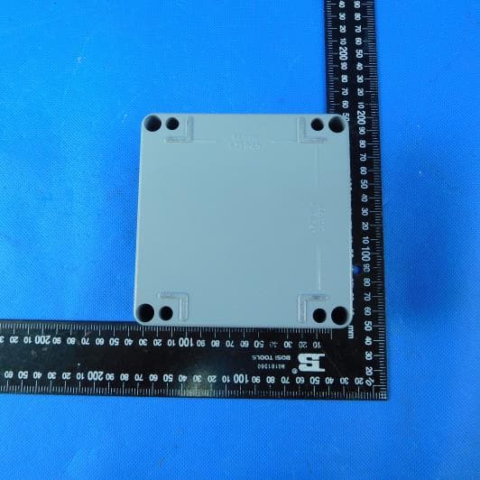
Click to zoom
Application Details
- Equipment Class
- DTS - Digital Transmission System
- Date of Grant
- Apr 28, 2020
- Application Purpose
- Original Equipment
- Date of Application
- Apr 27, 2020
- Equipment Note
- Wireless Tilt meter
- Frequency Range
- 902.50000000 - 927.50000000
- Country
- India
Documents & Files
Document Text
Text extracted from the exhibit documents filed with the FCC. Open a document above to read the original.
Users Manual
ONE STOP MONITORING SOLUTIONS | HYDROLOGY | GEOTECHNICAL | STRUCTURAL | GEODETIC Over 50 years of excellence through ingenuity USERS’ MANUAL ENCARDIO-RITE ELECTRONICS PVT. LTD. A-7, INDUSTRIAL ESTATE, TALKATORA ROAD, LUCKNOW, UP-226011, India | P: +91 522 2661039-42 | Email: [email protected] www.encardio.com International: UAE | Qatar | Bahrain | Bhutan | Europe | UK | USA India: Lucknow | Delhi | Kolkata | Mumbai | Chennai | Bangalore | Hyderabad | J&K Doc. # WI 6002.116 Rev. 01a | Jan 2020 Wireless Tilt meter MODEL EAN-95MW Users’ Manual EAN-95MW Wireless Tilt meter www.encardio.com Declaration of Conformity FCC Declaration of Conformity FCC Caution: Any changes or modifications not expressly approved by the party responsible for compliance could void the user's authority to operate this equipment. This device complies with part 15 of the FCC Rules. Operation is subject to the following two conditions: (1) This device may not cause harmful interference, and (2) this device must accept any interference received, including interference that may cause undesired operation. FCCRF Radiation Exposure Statement: 1. This Transmitter must not be co-located or operated in conjunction with any other antenna or transmitter. 2. This equipment complies with FCC radiation exposure limits set forth for an uncontrolled environment. 3. This equipment should be installed and operated with a minimum distance of 20cm between the radiator& your body. Users’ Manual EAN-95MW Wireless Tilt meter www.encardio.com Contents 1 INTRODUCTION 1 1.1 Applications 1 1.2 Conventions used in this manual 1 1.3 How to use this manual 1 2 GENERAL DESCRIPTION 3 2.1 System components 3 3 SAMPLE TEST CERTIFICATE 4 4 PRE-INSTALLATION PREPARATIONS 6 4.1 Pre-installation checks 6 4.2 Setting up the Gateway 6 5 INSTALLATION PROCEDURE 7 5.1 Tilt meter installation 7 5.2 Configuring tilt meter 7 5.2.1 Protection of tilt meter 13 5.2.2 Other considerations 13 5.3 Gateway installation 14 6 MEASUREMENT OF TILT 15 6.1 Sign convention 15 6.2 Environmental factors 15 Users’ Manual EAN-95MW Wireless Tilt meter Page | 1 1 INTRODUCTION Encardio-rite model EAN-95MWwirelesstilt meter is suitable for long term monitoring inclination and vertical rotation of structures. Continuous data logging and real-time monitoring helps to provide early warning in case of impending failure allowing time for corrective action to be taken or if necessary for safe evacuation of the area. Tilt change in a structure may be caused by construction activity like excavation, tunneling or de-watering that may affect the ground supporting the structure. Change in tilt could also result from loading of the structure, such as loading of a dam during impoundment, loading of a diaphragm wall during excavation or loading of a bridge deck due to wind and traffic. Data from the tilt meter provides early warning of threatening deformations, allowing time for corrective action to be taken or if necessary for safe evacuation of the area. 1.1 Applications EAN-95MWtilt meter is widely used in following applications: ▪ Monitoring vertical rotation of retaining walls. ▪ Monitoring inclination and rotation of dams, piers, piles and other structures. ▪ Monitoring stability of structures in landslide areas. ▪ Monitoring tunnels for convergence and other movement. ▪ Monitoring safety of structures around zones of excavation or tunnelling. ▪ Monitoring deflection in bridges and struts under different loading conditions. 1.2 Conventions used in this manual WARNING! Warning messages calls attention to a procedure or practice that if not properly followed, could possibly cause personal injury. CAUTION: Caution messages calls attention to a procedure or practice, that if not properly followed may result in loss of data or damage to equipment. NOTE: Note contains important information and is set off from the regular text to draw the users’ attention. 1.3 How to use this manual This users’ manual is intended to provide you with sufficient information for making optimum use of tilt meters in your applications. To make the manual more useful we invite valuable comments and suggestions regarding any additions or enhancements. We also request to please let us know of any errors that are found while going through the manual. Users’ Manual EAN-95MW Wireless Tilt meter Page | 2 NOTE: Installation personnel must have a background of good installation practices and knowledge of fundamentals of geotechnics. Novices may find it very difficult to carry on installation work. The intricacies involved in installation are such that even if a single essential but apparently minor requirement is ignored or overlooked, the most reliable of instruments will be rendered useless. A lot of effort has been made in preparing this instruction manual. However best of instruction manuals cannot provide for each and every condition in field that may affect performance of the sensor. Also, blindly following the instruction manual will not guarantee success. Sometimes, depending upon field conditions, installation personnel will have to consciously depart from written text and use their knowledge and common sense to find solution to a particular problem. Installation of a tilt meter requires expertise. It is recommended that potential users themselves practice all the operations laid down in this manual by repeated installations. NOTE: The sensor is normally used to monitor site conditions and will record even a minor change that may affect behaviour of structure being monitored. Some of these factors amongst others, are, seasonal weather changes, temperature, rain, barometric pressure, nearby landslides, earthquakes, traffic, construction activity around site including blasting, tides near sea coasts, fill levels, excavation, sequence of construction and changes in personnel etc. These factors must always be observed and recorded as they help in correlating data later on and also may give an early warning of potential da…
Text truncated - open the document above for the full version.
Cover Letter(s)
2020-04-28 Nemko Canada Inc 303 River Road Ottawa, Ontario, Canada K1V 1H2 Attn: Director of Certification Authority to Act as Agent On our behalf, I appoint Shenzhen Huatongwei International Inspection Co., Ltd./ 1/F, Bldg 3, Hongfa Hi-tech Industrial Park, Genyu Road, Tianliao, Gongming, Shenzhen, China / Hans Hu,. to act as our agent in the preparation of this application for equipment certification. I certify that submitted documents properly describe the device or system for which equipment certification is sought. I also certify that each unit manufactured, imported or marketed, as defined in the Federal Communications Commission’s regulations will have affixed to it a label identical to that submitted for approval with this application. For instances where our authorized agent signs the application for certification on our behalf, I acknowledge that all responsibility for complying with the terms and conditions for certification, as specified by Nemko Canada Inc, still resides with ENCARDIO RITE ELECTRONICS PVT. LTD. / A-7, INDUSTRIAL ESTATE, TALKATORA ROAD,LUCKNOW,UP-226011,India. Agency agreement expiration date: Apr.28, 2021 By: AMIT GUJRAL Signature Printed Title: Managing Director On behalf of : ENCARDIO RITE ELECTRONICS PVT. LTD. Telephone: +919839018182
Cover Letter(s)
2020-04-28 Equipment Autorisation Division Federal Communications Commission 7435 Oakland Mills Road Columbia, MD 21046 FCC ID: 2AU85-EAN-95MW Product Name: Wireless Tilt meter Request for Confidentiality Pursuant to Sections 0.457 and 0.459 of the commissions rules, we hereby request that the following documents be held confidential: (List here the documents for which you are seeking confidentiality – for example ...) Schematics Block diagram Operation description These materials contain trade secrets and proprietary information and are not customarily released to the public. The public disclosure of this information might be harmful to the company and provide unjustified benefits to our competitors. By: AMIT GUJRAL Signature Printed Title: Managing Director On behalf of : ENCARDIO RITE ELECTRONICS PVT. LTD. Telephone: +919839018182
External Photos
External Photos
Internal Photos
Internal Photos
RF Exposure Info
FCC ID: 2AU85-EAN-95MW RF Exposure Evaluation LIMIT The criteria listed in the following table shall be used to evaluate the environment impact of human exposure to radio frequency (RF) radiation as specified in 1.1307(b) Limits for Maximum Permissible Exposure (MPE) Frequency range (MHz) Electric field strength (V/m) Magnetic field strength (A/m) Power density (mW/cm 2 ) Averaging time (minutes) (A) Limits for Occupational/Controlled Exposures 0.3–3.0 614 1.63 *(100) 6 3.0–30 1842/f 4.89/f *(900/f 2 ) 6 30–300 61.4 0.163 1.0 6 300–1500 - - f/300 6 1500–100,000 - - 5 6 (B) Limits for General Population/Uncontrolled Exposure 0.3–1.34 614 1.63 *(100) 30 1.34–30 824/f 2.19/f *(180/f 2 ) 30 30–300 27.5 0.073 0.2 30 300–1500 - - f/1500 30 1500–100,000 - - 1.0 30 Note: f = frequency in MHz EVALUATION METHOD Transmission formula: Pd = (Pout*G)/(4*pi*r 2 ) Where Pd = power density in mW/cm 2 , Pout = output power to antenna in mW, G = gain of antenna in linear scale; Pi = 3.1416, R = distance between observation point and center of the radiator in cm TEST RESULT Passed Not Applicable FCC ID: 2AU85-EAN-95MW Conducted Average Power (dBm) Maximum Tune-up (dBm) Power Density (mW/cm2) Limit (mW/cm2) Result 9.54 10.00 0.004 1.0000 Pass Note: 1) The maximum antenna gain is 3dBi 2) The exposure evaluation safety distance is 20mm.
Test Report
Page: 1 of 36 TEST REPORT Report No. ...................................... : CHTEW20030099 Report Verification: Project No.................................: SHT2002005703EW FCC ID ............................................. : 2AU85-EAN-95MW Applicant’s name ........................... : ENCARDIO RITE ELECTRONICS PVT. LTD. Address ............................................. : A-7, INDUSTRIAL ESTATE, TALKATORA ROAD,LUCKNOW,UP-226011,India Manufacturer.....................................: ENCARDIO RITE ELECTRONICS PVT. LTD. Address..............................................: A-7, INDUSTRIAL ESTATE, TALKATORA ROAD,LUCKNOW,UP-226011,India Test item description .................... : Wireless Tilt meter Trade Mark ....................................... : - Model/Type reference ....................... : EAN-95MW Listed Model(s) ................................. : - Standard ......................................... : FCC CFR Title 47 Part 15 Subpart C Section 15.247 Date of receipt of test sample..........: Mar.11, 2020 Date of testing.............................: Mar.11, 2020- Mar.18, 2020 Date of issue...............................: Mar.19, 2020 Result .................. ........................: PASS Compiled by ( Position+Printed name+Signature): File administrator Echo Wei Supervised by (Position+Printed name+Signature): Project Engineer Kiki Kong Approved by (Position+Printed name+Signature): RF Manager Hans Hu Testing Laboratory Name ............. : Shenzhen Huatongwei International Inspection Co., Ltd. Address ............................................. : 1/F, Bldg 3, Hongfa Hi-tech Industrial Park, Genyu Road, Tianliao, Gongming, Shenzhen, China Shenzhen Huatongwei International Inspection Co., Ltd. All rights reserved. This publication may be reproduced in whole or in part for non-commercial purposes as long as the Shenzhen Huatongwei International Inspection Co., Ltd. is acknowledged as copyright owner and source of the material. Shenzhen Huatongwei International Inspection Co., Ltd. takes no responsibility for and will not assume liability for damages resulting from the reader's interpretation of the reproduced material due to its placement and context. The test report merely correspond to the test sample. Report No.: CHTEW20030099 Page: 2 of 36 Issued: 2020-03-19 Shenzhen Huatongwei International Inspection Co., Ltd. Report Template Version: V02 (2019-10) Contents 1. TEST S T A N D A R D S AND R E P O R T V E R S I O N 3 1.1. Test Standards 3 1.2. Report version 3 2. TEST DESCRIPTION 4 3. SUMMARY 5 3.1. Client Information 5 3.2. Product Description 5 3.3. Radio Specification Description 5 3.4. Testing Laboratory Information 6 4. TEST CONFIGURATION 7 4.1. Test frequency list 7 4.2. Test mode 7 4.3. Support unit used in test configuration and system 7 4.4. Testing environmental condition 8 4.5. Measurement uncertainty 8 4.6. Equipment Used during the Test 9 5. TEST CONDITIONS AND RESULTS 11 5.1. Antenna Requirement 11 5.2. AC Conducted Emission 12 5.3. Peak Output Power 13 5.4. Power Spectral Density 14 5.5. 6dB bandwidth 15 5.6. 99% Occupied Bandwidth 16 5.7. Duty Cycle 17 5.8. Conducted Band edge and Spurious Emission 18 5.9. Radiated Band edge Emission 20 5.10. Radiated Spurious Emission 22 6. TEST SETUP PHOTOS 27 7. EXTERANAL AND INTERNAL PHOTOS 29 8. APPENDIX REPORT 36 Report No.: CHTEW20030099 Page: 3 of 36 Issued: 2020-03-19 Shenzhen Huatongwei International Inspection Co., Ltd. Report Template Version: V02 (2019-10) 1. TEST STANDARDS AND REPORT VERSION 1.1. Test Standards The tests were performed according to following standards: ‒ FCC Rules Part 15.247: Frequency Hopping, Direct Spread Spectrum and Hybrid Systems that are in operation within the bands of 902-928 MHz, 2400-2483.5 MHz, and 5725-5850 MHz ‒ ANSI C63.10:2013: American National Standard for Testing Unlicensed Wireless Devices ‒ KDB 558074 D01 15.247 Meas Guidance v05r02: Guidance for Compliance Measurements on Digital Transmission System, Frequency Hopping Spread Spectrum System, and Hybrid System Devices Operating under Section 15.247 of The FCC Rules 1.2. Report version Revision No. Date of issue Description N/A 2020-03-19 Original Report No.: CHTEW20030099 Page: 4 of 36 Issued: 2020-03-19 Shenzhen Huatongwei International Inspection Co., Ltd. Report Template Version: V02 (2019-10) 2. TEST DESCRIPTION Report clause Test Items Standard Requirement Result 5.1 Antenna Requirement 15.203/15.247(c) PASS 5.2 AC Conducted Emission 15.207 N/A 5.3 Peak Output Power 15.247(b)(3) PASS 5.4 Power Spectral Density 15.247(e) PASS 5.5 6dB Bandwidth 15.247(a)(2) PASS 5.6 99% Occupied Bandwidth - PASS *1 5.7 Duty cycle - PASS *1 5.8 Conducted Band Edge and Spurious Emission 15.247(d)/15.205 PASS 5.9 Radiated Band Edge Emission 15.205/15.209 PASS 5.10 Radiated Spurious Emission 15.247(d)/15.205/15.209 PASS Note: ‒ The measurement uncertainty is not included in the test result. ‒ *1: No requirement on standard, only report these test data. Report No.: CHTEW20030099 Page: 5 of 36 Issued: 2020-03-19 Shenzhen Huatongwei International Inspection Co., Ltd. Report Template Version: V02 (2019-10) 3. SUMMARY 3.1. Client Information Applicant: ENCARDIO RITE ELECTRONICS PVT. LTD. Address: A-7, INDUSTRIAL ESTATE, TALKATORA ROAD,LUCKNOW,UP- 226011,India Manufacturer: ENCARDIO RITE ELECTRONICS PVT. LTD. Address: A-7, INDUSTRIAL ESTATE, TALKATORA ROAD,LUCKNOW,UP- 226011,India 3.2. Product Description Name of EUT: Wireless Tilt meter Trade Mark: - Model No.: EAN-95MW Listed Model(s): - Power supply: DC 3.6V Hardware version: 2.0 Software version: 4.3.200203 3.3. Radio Specification Description Modulation: 2-GFSK Operation frequency: 902MHz - 928MHz Channel number: 50 Channel separation: - Antenna type: Omnidirectional Dipole Antenna Antenna gain: 3 dBi Report No.: CHTEW20030099 Page: 6 of 36 Issued: 2020-03-19 Shenzhen Huatongwei International Inspection Co., Ltd. Report Template Version: V02 (2019-10) 3.4. Testing Laboratory Inform…
Text truncated - open the document above for the full version.
Test Setup Photos
TEST SETUP PHOTOS Radiated Emission
Contact Information
Applicant
AMIT GUJRAL
Test Firm
Shenzhen Huatongwei International Inspection Co.,Tony Jiang
[email protected]+86-755-26748078
Technical Specifications
| # | Rule Parts | Frequency Range | Power Output |
|---|---|---|---|
| 1 | 15C | 902.5 MHz - 927.5 MHz | 9.00 mW |
Other Applications from ENCARDIO-RITE ELECTRONICS PVT. LTD.
2AU85-EAN-95M
Sep 04, 2024NEXAWAVE TiltSense
Equipment Class
DTS - Digital Transmission System