2AU9T-CART1RCART-I
Sky Labs Inc.
Click to zoom
Application Details
- Equipment Class
- DTS - Digital Transmission System
- Date of Grant
- Feb 12, 2020
- Application Purpose
- Original Equipment
- Date of Application
- Feb 12, 2020
- Equipment Note
- CART-I
- Frequency Range
- 2402.00000000 - 2480.00000000
- Company
- Sky Labs Inc.
- Country
- South Korea
Documents & Files
Document Text
Text extracted from the exhibit documents filed with the FCC. Open a document above to read the original.
Users Manual
F401-01(A-190102) Sky Labs Inc. Instructions for use(IFU)(CART-I) Sky Labs Inc. #703, C's tower, 58, Pangyo-ro 255beon-gil, Bundang-gu, Seongnam-si, Gyeonggi-do, Korea F401-01(A-190102) Sky Labs Inc. ◆ Approval Author Review Review Review Review Dept. Name or Position R&D RA BD manager R&D manager CEO Name Sungmi Jo Kyungeun Yoo Yumi Ji Changhyun Baik Byunghwan Lee Signature Date ◆ Revision information No. Date Description Remark 0 2019.05.24 Initial release 1 2019.12.18 Corrective action of 1 st MTIC review & add the FCC requirements F401-01(A-190102) Sky Labs Inc. ◆ 목 차(Contents) Chapter Contents Remark 1 Device description & Intended use 2 Packages 3 Device specification 4 Environment specification 5 Symbols 6 Safety Precautions 7 Contraindications 8 Disposal 9 Warranty 10 Installation & Charging 11 Operation 12 Information on EMC 14 FCC Compliance state 15 Troubleshooting F401-01(A-190102) Sky Labs Inc. Instruction For Use CART-I by Sky Labs Inc. Thank you for choosing CART-I. Please read this Instruction for use, including all Precautionary information and instructions, before using your device. Failure to follow the instructions below could result in device damage or malfunction, or even injury. The issue date for IF-01(revision 1) is December 2019. If more than three years have elapsed since this date, contact Sky Labs Inc. to determine if additional device information updates are available. If you have any questions about using your device or mobile app, please contact Sky Labs Inc. Sky Labs Inc. #703, 58, Pangyo-ro 255beon-gil, Bundang-gu, Seongnam-si, Gyeonggi-do, Korea www.i-skylabs.com Tel: +82-31-8092-3290 CE Medical Amerlandseweg 7, 3621ZC, Breukelen, the Netherlands IF-01(revision 1) Dec 2019 F401-01(A-190102) Sky Labs Inc. CHAPTER 1. Device description & Intended use CART-I consists of devices, including CART-Ring and CART-Cradle, CART-App(Mobile Application) for general users, and CART-Web(website) for doctors. CART-I provides photoplethysmography(PPG) signals to measure heart rate(HR) and to identify Atrial Fibrillation or its burden, and electrocardiogram(ECG) signals to offer supplementary information to doctors. A part of CART-I, CART-Ring is a ring-type wearable device, which collects(or records), stores, and transfers not only PPG signals but also single-channel ECG signals. CART-Ring operates continuously to collect only PPG signals - referred to as "Background-Check" within this submission -without user intervention, while collecting both PPG and ECG signals - referred to as "Self-Check" within this submission -by users' intention. Inside of CART-Ring, a Lithium Polymer battery can be recharged using CART-Cradle, operating based on the wireless charging technique. CART-I utilizes an iOS-based CART-App, which is installed on an iPhone, to obtain PPG and ECG signals from CART-Ring. After obtaining both signals, CART-App transmits those signals to a cloud server to get results, such as an estimation of HR and an analysis of Atrial Fibrillation or not. CART-App offers the statistics, including the number of checks, the analyzed results, and etc., with graphs and lists to users; Data offered to users are synchronized to their own account. After connecting to users, doctors get more detailed information from a cloud server for their connected users than those for general users using CART-Web. CHAPTER 2. Packages NOT including the mobile phone to install the application, CART-app and adapter . You’ll additionally need the followings to operate the device of Sky Labs Inc. mobile phone : >iPhone 6, >iOS10.0, BLE(BT 5.0) CART-App is available in the Apple App Store. F401-01(A-190102) Sky Labs Inc. CHAPTER 3. Device specification 1. Product name : Heart Monitor 2. Trade name / Model name : CART-I 3. Model Number Model number of full packages(set) Model number of CART-Ring Model number of CART-Cradle A0K1 R0K1 C0K1 A0K2 R0K2 C0K2 A0K3 R0K3 C0K3 A0K4 R0K4 C0K4 A0K5 R0K5 C0K5 A0K6 R0K6 C0K6 A0K7 R0K7 C0K7 A0K8 R0K8 C0K8 4. Intended use CART-I is indicated for self-testing by patients who have been diagnosed with, or are susceptible to developing, atrial fibrillation or its burden and who would like to monitor and record their heart rhythms and heart rates on an intermittent or continuous basis. CART-I is intended to be used in the home-healthcare environment. 5. General information Part Feature CART-Ring Rated Power Internally Powered, Lithium polymer battery, 3.7 Vd.c. Max power(R0K1) -4 dBm(Burst Average power) BT frequency Charging frequency : 205kHz Operating frequency : 2402-2480MHz IP Grade IP58 Temperature -20°C ~ 50°C Mode of operation Continuous Protection against electric shock Grade II / Internally Powered, BF type applied part, Body-worn RF specification Bluetooth Low Energy, Bluetooth 5.0, distance: <2m Firmware Ver.1.0.0 CART-Cradle Rated Power 5Vd.c. Rated Power Consumption 50mW~5W Charging method Wireless Charging / Operating Frequency < 205kHz / Magnetic Inductive / using USB cable CART-App Ver. 1.0.0 Language : English 6. Applied part Inner metal, sensor and outer of CART-Ring 7. Product life time CART-I is guaranteed to last for a minimum of 2 years. F401-01(A-190102) Sky Labs Inc. CHAPTER 4. Environment specification Item Description Operating & Charging Temperature 5°C~45°C Operating & Charging Humidity 10%~95% Storage/Transport Temperature -25°C to 70°C Storage/Transport Humidity 10%~95% Operating & Storage/Transport Atmospheric Pressure 700hPa to 1060hPa CHAPTER 5. Symbols 1. Box symbols Fragile, handle with care Keep dry Limitation for Transport and storage 2. Device Symbols Manufacturer information CE marking of conformity Serial number Temperature limitation Type BF Humidity limitation Date of manufacture Atmospheric pressure limitation Refer to the Instruction for use Manufacturer’s EU Representative information F401-01(A-190102) Sky Labs Inc. IP Grade Do not dispose with household waste Direct current 3. IFU Symbols Warning : Indicates a potenti…
Text truncated - open the document above for the full version.
Cover Letter(s)
Sky Labs Inc. #703, 58, Pangyo-ro 255beon-gil Bundang-gu, Seongnam-si Gyeonggi-do South Korea Date: 02/06/2020 Timco Engineering, Inc. 849 N.W. State Road 45 P.O. Box 370 Newberry, Florida 32669 USA Letter of Authorization We, the undersigned, hereby authorize Guenki Son of DT&C Co., Ltd. to act on our behalf in all manners relating to application for equipment authorization for FCC ID: 2AU9T-CART1R including signing of all documents relating to these matters. Any and all acts carried out by Guenki Son of DT&C Co., Ltd. on our behalf shall have the same affect as acts of our own. This authorization is valid until further written notice from Sky Labs Inc. “I, the undersigned, hereby certify that we are not subject to a denial of federal benefits, that includes FCC benefits, pursuant to Section 5301 of the Anti-Drug Abuse Act of 1988, 21 U.S.C. 853(a).” Sincerely, Jack Lee CEO
Cover Letter(s)
Sky Labs Inc. #703, 58, Pangyo-ro 255beon-gil Bundang-gu, Seongnam-si Gyeonggi-do South Korea Date: Feb 06, 2020 Timco Engineering, Inc. 849 N.W. State Road 45 P.O. Box 370 Newberry, Florida 32669 USA RE: Request of Confidentiality for FCC ID: 2AU9T-CART1R To Whom It may Concern: Pursuant to Sections 0.457 and 0.459 of the Commission`s Rules(CFR 47), and Section 552 (b) (4) of the Freedom of Information Act, Sky Labs Inc. hereby requests confidentiality and treatment of certain information accompanying this application. The materials contain trade secrets and proprietary information not customarily released to the public. The public disclosure of these matters might be harmful to the Applicant and provide unjustified benefits to its competitors. We are also hereby request Short-Term Confidentiality for 180 days after the grant as outlined in Public Notice DA 04-1705. This provision will give Sky Labs Inc. temporary confidentiality of commercially sensitive information prior to product release. The requested permanent and Short-Term Confidential exhibits are listed as follows: PERMANENT & SHORT-TERM CONFIDENTIAL LIST Exhibit Description PERMANENT 1 Block Diagram 2 Schematics 3 Part Lists 4 Operation Description SHORT-TERM 5 Internal Photos 6 External Photos 7 Test-Setup Photos 8 User Manual The Applicant understands that pursuant to Rule 0.457, disclosure of this application and all accompanying documentations, where applicable, will not be public before the date of the Grant for this application. Sincerely, Jack Lee CEO
External Photos
FCC ID : 2AU9T-CART1R Copyright Ⓒ 2020, DT&C Co., Ltd. View 1 FCC ID : 2AU9T-CART1R Copyright Ⓒ 2020, DT&C Co., Ltd. View 2 FCC ID : 2AU9T-CART1R Copyright Ⓒ 2020, DT&C Co., Ltd. View 3
ID Label/Location Info
FCC ID: 2AU9T-CART1R Copyright Ⓒ 2020 DT&C Co., Ltd. SAMPLE LABEL & LOCATION LABELLING REQUIREMENTS The Label shown shall be permanently affixed at a conspicuous location on the device and be readily visible to the user at the time of purchase. - The FCC label shown is representative of the label that will appear on the radio when in production. Other information may also be included on this label.
Internal Photos
FCC ID : 2AU9T-CART1R Copyright Ⓒ 2020, DT&C Co., Ltd. View 1 FCC ID : 2AU9T-CART1R Copyright Ⓒ 2020, DT&C Co., Ltd. View 2 FCC ID : 2AU9T-CART1R Copyright Ⓒ 2020, DT&C Co., Ltd. View 3 <Antenna> FCC ID : 2AU9T-CART1R Copyright Ⓒ 2020, DT&C Co., Ltd. View 4 <Antenna> <Antenna>
RF Exposure Info
FCC ID: Date: RF feautureMode Transmitting Frequency(MHz) Test separation distance (mm) Note2 ANT Gain (dBi) Max. power with tune-up tolerance (dBm) Note1 Max. power with tune-up tolerance (mW) Power thresholds (mW) SAR test exclusion thresholds(mW) at separation distance of 5 mm BTLE(1,2Mbps)2480.005.01.00-4.500.35480.117.50 Note1. Note2. Conclusion : 2AU9T-CART1R Standalone SAR test exclusion considerations:LE February 10, 2020 Please refer to the operation description for Max tune-up. SAR evaluation for general population exposure conditions by measurement or numerical simulation is not required KDB 447498 D01 clasue 4.3.1 Step 1) SAR test exclusion thresholds for 100MHz to 6GHz at test separationn distances ≤ 50 mm [ ( max. power of channel, including tune-up tolerance, mW ) / ( min. test separation distance, mm ) ] · [ √f(GHz) ] ≤ 3.0 for 1g SAR and ≤ 7.5 for 10g extremity SAR Sample Calculation = [ ( 0.3548mW / 5mm ) ] X [ √2.48GHz ] = 0.11 Note. The calculation result was rounded to two decimal place for comparison.
Test Report
Report No.: DRTFCC2002-0034 FCC ID: 2AU9T-CART1R TRF-RF-238(05)170516 Prohibits the copying and re-issue of this report without DT&C approval. Pages: 2 / 60 Test Report Version Test Report No. Date Description Revised By Reviewed By DRTFCC2002-0034 Feb. 11, 2020 Initial issue JungWoo Kim JaeJin Lee Report No.: DRTFCC2002-0034 FCC ID: 2AU9T-CART1R TRF-RF-238(05)170516 Prohibits the copying and re-issue of this report without DT&C approval. Pages: 3 / 60 Table of Contents 1. General Information .................................................................................... 4 1.1 Testing Laboratory ........................................................................................................... 4 1.2 Test Environment ............................................................................................................. 4 1.3 Measurement Uncertainty ................................................................................................ 4 1.4 Details of Applicant .......................................................................................................... 5 1.5 Description of EUT ........................................................................................................... 5 1.6 Declaration by the applicant / manufacturer ................................................................. 5 1.7 Test Equipment List ......................................................................................................... 6 1.8 Summary of Test Results ................................................................................................ 7 2. Test Methodology ........................................................................................ 8 2.1 EUT Configuration ............................................................................................................ 8 2.2 EUT Exercise ..................................................................................................................... 8 2.3 General Test Procedures ................................................................................................. 8 2.4 Description of Test Modes ............................................................................................... 8 2.5 Instrument Calibration ..................................................................................................... 8 3. Test Result ................................................................................................... 9 3.1 Maximum Peak Conducted Output Power ..................................................................... 9 3.1.1 Test Setup ..................................................................................................................... 9 3.1.2 Test Procedures ........................................................................................................... 9 3.1.3 Test Results .................................................................................................................. 9 3.2 6 dB Bandwidth Measurement ...................................................................................... 14 3.2.1 Test Setup ................................................................................................................... 14 3.2.2 Test Procedures ......................................................................................................... 14 3.2.3 Test Results ................................................................................................................ 14 3.3 Maximum Power Spectral Density. ............................................................................... 19 3.3.1 Test Setup ................................................................................................................... 19 3.3.2 Test Procedures ......................................................................................................... 19 3.3.3 Test Results ................................................................................................................ 19 3.4 Unwanted Emissions (Conducted) ............................................................................... 24 3.4.1 Test Setup ................................................................................................................... 24 3.4.2 Test Procedures ......................................................................................................... 24 3.4.3 Test Results ................................................................................................................ 25 3.5 Unwanted Emissions (Radiated) ................................................................................... 41 3.5.1 Test Setup ................................................................................................................... 42 3.5.2 Test Procedures ......................................................................................................... 42 3.5.3 Test Results ................................................................................................................ 43 3.6 Power line Conducted Emissions ................................................................................. 47 3.6.1 Test Setup ................................................................................................................... 47 3.6.2 Test Procedures ......................................................................................................... 47 3.6.3 Test Results ................................................................................................................ 47 3.7 Occupied Bandwidth ...................................................................................................... 48 3.7.1 Test Setup ................................................................................................................... 48 3.7.2 Test Procedures ..................................................................................…
Text truncated - open the document above for the full version.
Test Setup Photos
FCC ID : 2AU9T-CART1R Copyright Ⓒ 2020, DT&C Co., Ltd. Test Setup Photo of Radiated Measurement EUT Position: X-axis EUT Position: Y-axis EUT Position: Z-axis FCC ID : 2AU9T-CART1R Copyright Ⓒ 2020, DT&C Co., Ltd. Test Setup Photo of Radiated Measurement (0.009 ~ 30MHz) FCC ID : 2AU9T-CART1R Copyright Ⓒ 2020, DT&C Co., Ltd. Test Setup Photo of Radiated Measurement (below 1000MHz)) FCC ID : 2AU9T-CART1R Copyright Ⓒ 2020, DT&C Co., Ltd. Test Setup Photo of Radiated Measurement (Above 1GHz)
Contact Information
Applicant
Jack Lee(Representative)
Test Firm
Dt&C Co., Ltd.Lee Sang-Wook
Technical Specifications
| # | Rule Parts | Frequency Range | Power Output |
|---|---|---|---|
| 1 | 15C | 2.40 GHz - 2.48 GHz | 400.00 µW |
Other Applications from Sky Labs Inc.
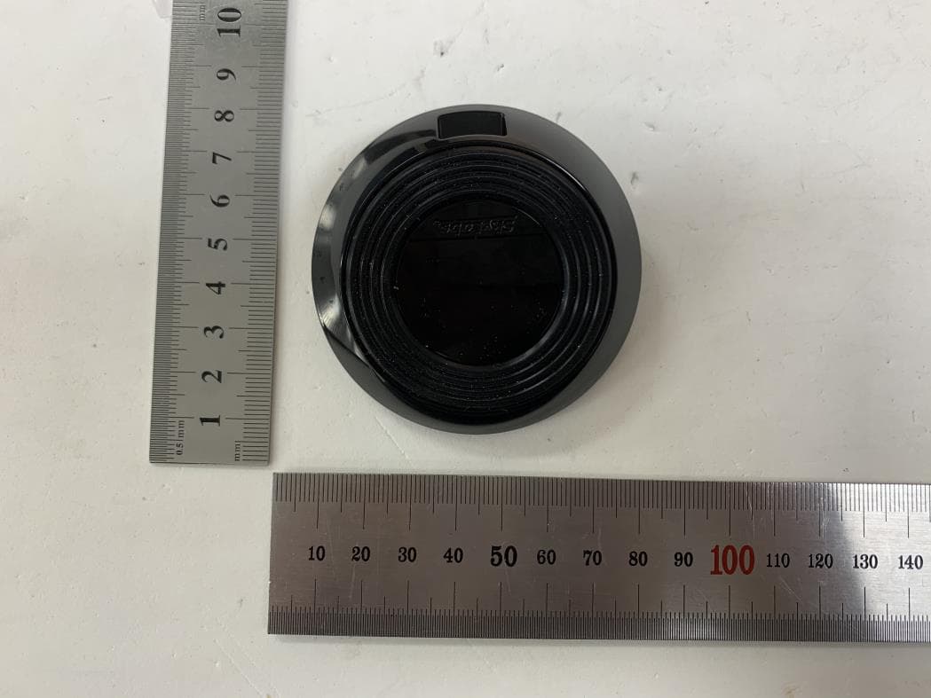
2AU9T-CART1C
Feb 13, 2020CART-I
Equipment Class
DCD - Part 15 Low Power Transmitter Below 1705 kHz