2AU9W-CUBIBOTCubibot
InnoSun LLC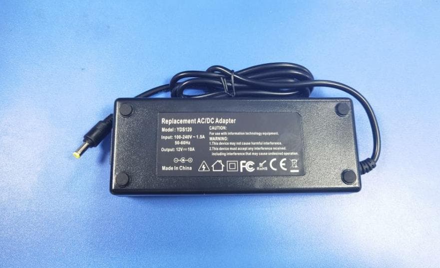
Click to zoom
Application Details
- Equipment Class
- DTS - Digital Transmission System
- Date of Grant
- May 25, 2021
- Application Purpose
- Original Equipment
- Date of Application
- May 25, 2021
- Equipment Note
- Cubibot
- Frequency Range
- 2412.00000000 - 2462.00000000
- Company
- InnoSun LLC
- Country
- United States
Documents & Files
Document Text
Text extracted from the exhibit documents filed with the FCC. Open a document above to read the original.
Users Manual
Quick use guide Model: Cubibot Congratulations! In this brief guide, we’re going to show you how to set up and make your first model on the new Cubibot Desktop 3D Printer. Your purchase comes with a complimentary, live training session with one of our technicians. For advanced users, see our website for tips & tricks. We’re so excited to see what you make! 1. In the Box Cubibot Print material power adapter 2. Where to Set Up Use the provided power cable to plug your printer into a surge protector or uninterrupted power supply. Pro automatically goes to sleep to save energy after a period of inactivity. Interaction with the touchscreen or sending a print job will reactivate it. Use the power switch if you need to perform a hard reset or disconnect your Pro from its power source. 3. Plug in power Use the provided power cable to plug your printer into a surge protector or uninterrupted power supply. Pro automatically goes to sleep to save energy after a period of inactivity. Interaction with the touchscreen or sending a print job will reactivate it. Use the power switch if you need to perform a hard reset or disconnect your Pro from its power source. 4.prepare print Job Using Desktop Software to Prepare a PrintAfter launching, begin by selecting your printing material and the desired layer thickness. Next, import your STL model, orient the model, and add supports if necessary. If you are new to 3D printing, consult our website and full user manual for more detailed information. The model is now ready for printing. Now that everything is set on the software side, follow the below instructions to prepare your printer. The printer feeds, operating the machine to find the feeding function, and then manually insert the material into the machine's feed port. After the machine is heated, the material will automatically enter. After the printer nozzle is spinning normally, the feed can be cancelled. If you want to change the print model, click Cancel, reselect the print function, find the file you want to print, and click directly to print. After printing, please carefully remove the model with scissors and a small spatula. 5. Maintenance Resin Tank Inspection Gently drag the resin wiper across the surface of the tank to ensure there are no hard particles in the tank. Mixing Resin Before Print If you keep resin in the tank between jobs, use the resin wiper to mix the tank before every print. Cleaning the Printer Use the cleaning cloth provided with the printer to clean the glass on the printer. Clean the printer with a soft damp cloth. Resin Care Cured resin can be discarded as regular trash. Never dispose of liquid resin in your sink or other plumbing. Resin should not be left out of the bottle for more than three days. If it has been exposed to air for less than three days, it is safe to pour it back into the bottle through a paper filter or loose mesh. Warning: Changes or modifications to this unit not expressly approved by the party responsible for compliance could void the user’s authority to operate the equipment. NOTE:This device is a fix location and is dangerous. Please be careful when using it. NOTE:When the instrument is in normal working condition, please keep at least 20CM distance to avoid high temperature or splashing objects. NOTE: This device complies with part 15 of the FCC Rules. Operation is subject to the following two conditions: (1) This device may not cause harmful interference, and (2) this device must accept any interference received, including interference that may cause undesired operation. NOTE: This equipment has been tested and found to comply with the limits for a Class B digital device, pursuant to part 15 of the FCC Rules. These limits are designed to provide reasonable protection against harmful interference in a residential installation. This equipment generates, uses and can radiate radio frequency energy and, if not installed and used in accordance with the instructions, may cause harmful interference to radio communications. However, there is no guarantee that interference will not occur in a particular installation. If this equipment does cause harmful interference to radio or television reception, which can be determined by turning the equipment off and on, the user is encouraged to try to correct the interference by one or more of the following measures: —Reorient or relocate the receiving antenna. —Increase the separation between the equipment and receiver. —Connect the equipment into an outlet on a circuit different from that to which the receiver is connected. — Consult the dealer or an experienced radio/TV technician for help.
Cover Letter(s)
InnoSun LLC Agent Authorization Company:InnoSun LLC Address: 7310 Miramar Rd #100, San Diego, CA 92126 Product Name: Cubibot Model Number(s): Cubibot Product Description: Cubibot We authorize MiCOM Labs Inc., 575 Boulder Court, Pleasanton, California 94566, USA, to act on our behalf on all matters concerning the certification of above named equipment. We declare that MiCOM Labs Inc. is allowed to forward all information related to the approval and certification of equipment to the regulatory agencies as required and to discuss any issues concerning the approval application. Any and all acts carried out by MiCOM Labs on our behalf shall have the same effect as acts of our own. Date: Apr. 29, 2021 Signature: Name:Aria Noorazar Title: manager Company: InnoSun LLC
Cover Letter(s)
InnoSun LLC Date: May 05, 2021 Office of Engineering Technology Federal Communications Commission 7435 Oakland Mills Road Columbia, MD 21046 USA Subject; Request for Confidentiality FCC ID: 2AU9W-CUBIBOT To Whom It May Concern, Pursuant to the provisions of the Commission’s rules Title 47 Sections §0.457 and §0.459, we are requesting the Commission to withhold the following attachment(s) as confidential documents from public disclosure indefinitely. These documents contain detailed system and equipment descriptions and are considered as proprietary information in operation of the equipment. The public disclosure of these documents might be harmful to our company and would give competitors an unfair advantage in the market. Schematic Diagram Block Diagram Parts List Operational Description Tune-up Procedure In additional to above mentioned documents, in order to comply with the marketing regulations in Title 47 CFR §2.803 and the importation rules in Title 47 CFR §2.1204, while ensuring that business sensitive information remains confidential until the actual marketing of newly authorized devices, we request Short Term Confidentiality of the following attachment(s); External Photos Test Setup Photos Internal Photos User Manual For 45 days, pursuant to Public Notice DA 04-1705. OR For 180 days pursuant to KDB 726920 D01. It is our understanding that all measurement test reports, FCC ID label format and correspondence during the certification review process cannot be granted as confidential documents and this information will be available for public review once the grant of equipment authorization is issued. Sincerely, Signature: Name:Aria Noorazar Title: manager
ID Label/Location Info
Label location Label sample: Label size:30*70mm Cubibot FCC ID: 2AU9W-CUBIBOT This device complies with part 15 of the FCC Rules. Operation is subject to the following two conditions: (1) This device may not cause harmful interference, and (2) this device must accept any interference received, including interference that may cause undesired operation.
RF Exposure Info
RF Exposure Evaluation Test report On Behalf of InnoSun LLC For Cubibot Model No.: Cubibot FCC ID: 2AU9W-CUBIBOT Prepared for : InnoSun LLC 7310 Miramar Rd #100, San Diego, CA 92126 Prepared By : Shenzhen HUAK Testing Technology Co., Ltd. 1F, B2 Building, Junfeng Zhongcheng Zhizao Innovation Park, Fuhai Street, Bao'an District, Shenzhen City, China Date of Test: Nov. 18, 2019 ~ Dec. 30, 2020 Date of Report: Dec. 30, 2020 1 General Description of EUT Equipment Cubibot Model Name Cubibot Serial No. N/A Trade Mark Cubibot 3D Printer FCC ID 2AU9W-CUBIBOT Hardware Version: V1.0 Software Version: V2.2.3 Operation frequency 802.11b/g/n 20: 2412~2462 MHz Number of Channels 802.11b/g/n20: 11CH Antenna Type PCB Antenna Antenna Gain 0dBi Modulation Type CCK/DSSS/OFDM Power Source DC 12V from adapter 2 RF Exposure Compliance Requirement 2.1 Standard Requirement According to FCC Part1.1310: The criteria listed in the following table shall be used to evaluate the environment impact of human exposure to radio frequency (RF) radiation as specified in part1.1307(b) F= Frequency in MHz Friis Formula Friis transmission formula: Pd = (Pout*G)/(4* Pi * R 2) Where Pd = power density in mW/cm2 Pout = output power to antenna in mW G = gain of antenna in linear scale Pi = 3.1416 R = distance between observation point and center of the radiator in cm Pd id the limit of MPE . If we know the maximum gain of the antenna and the total power input to the antenna, through the calculation, we will know the distance r where the MPE limit is reached. 3 EUT RF Exposure Antenna Gain: 0Bi Antenna Gain: The maximum Gain measured in fully anechoic chamber is in linear scale. Output Power Into Antenna & RF Exposure Evaluation Distance: Measurement Data 802.11b mode Test channel Peak OutputPower (dBm) Tune up tolerance (dBm) Maximum tune-up Power (dBm) (mW) Lowest(2412MHz) 14.03 14±1 15 31.623 Middle(2437MHz) 13.44 14±1 15 31.623 Highest(2462MHz) 13.77 14±1 15 31.623 802.11g mode Test channel Peak OutputPower (dBm) Tune up tolerance (dBm) Maximum tune-up Power (dBm) (mW) Lowest(2412MHz) 15.80 15±1 16 39.811 Middle(2437MHz) 15.28 15±1 16 39.811 Highest(2462MHz) 14.56 15±1 16 39.811 802.11n20 mode Test channel Peak OutputPower (dBm) Tune up tolerance (dBm) Maximum tune-up Power (dBm) (mW) Lowest(2412MHz) 15.64 15±1 16 39.811 Middle(2437MHz) 15.13 15±1 16 39.811 Highest(2462MHz) 14.52 15±1 16 39.811 Worst case: 802.11g mode -Lowest(2412MHz) (Using the maximum value of the test report) Maximum tune-up Power (mW) Antenna Gain (dBi) Power Density at R = 20 cm (mW/cm2) Limit Result 39.811 0 0.00792 1 PASS Remark: 1) The Max Conducted Peak Output Power data refer to report Report No.: HK1912033081-E 2) Pd = (Pout*G)/(4* Pi * R2)=( 39.811*1)/(4*3.1416*20 2 )= 0.00792 mW/cm2
Test Report
Report No.: HK1912033081-E FCC TEST REPORT Test report On Behalf of InnoSun LLC For Cubibot Model No.: Cubibot FCC ID: 2AU9W-CUBIBOT Prepared for : InnoSun LLC 7310 Miramar Rd #100, San Diego, CA 92126 Prepared By : Shenzhen HUAK Testing Technology Co., Ltd. 1F, B2 Building, Junfeng Zhongcheng Zhizao Innovation Park, Fuhai Street, Bao'an District, Shenzhen City, China Date of Test: Dec. 28, 2020 ~ May 26, 2021 Date of Report: May 26, 2021 Report Number: HK1912033081-E Report No.: HK1912033081-E Page 2 of 64 TEST RESULT CERTIFICATION Applicant’s name ................. : InnoSun LLC Address ................................. : 7310 Miramar Rd #100, San Diego, CA 92126 Manufacture's Name ............ : InnoSun LLC Address ................................. : 7310 Miramar Rd #100, San Diego, CA 92126 Product description Trade Mark : Cubibot 3D Printer Product name ...................... : Cubibot Model and/or type reference : Cubibot Standards ............................. : Part 15 Subpart C Section 15.247 ANSI C63.10: 2013 KDB558074 D01 15.247 Meas Guidance v05r02 This publication may be reproduced in whole or in part for non-commercial purposes as long as the Shenzhen HUAK Testing Technology Co., Ltd. is acknowledged as copyright owner and source of the material. Shenzhen HUAK Testing Technology Co., Ltd. takes no responsibility for and will not assume liability for damages resulting from the reader's interpretation of the reproduced material due to its placement and context. Date of Test ........................................... : Date (s) of performance of tests ............. : Dec. 28, 2020 ~ May 26, 2021 Date of Issue .......................................... : May 26, 2021 Test Result ............................................. : Pass Testing Engineer : (Gary Qian) Technical Manager : (Eden Hu) Authorized Signatory : (Jason Zhou) Report No.: HK1912033081-E Page 3 of 64 TABLE OF CONTENTS 1. Test Result Summary............................................................................................................................... 4 1.1. TEST PROCEDURES AND RESULTS ............................................................................................. 4 1.2. TEST FACILITY ................................................................................................................................. 4 1.3. Measurement Uncertainty ................................................................................................................. 5 2. EUT Description ....................................................................................................................................... 6 2.1. GENERAL DESCRIPTION OF EUT ................................................................................................. 6 2.2. Carrier Frequency of Channels ......................................................................................................... 6 2.3. Operation of EUT during testing ........................................................................................................ 6 2.4. DESCRIPTION OF TEST SETUP ..................................................................................................... 7 3. Genera Information .................................................................................................................................. 8 3.1. T est environment and mode .............................................................................................................. 8 3.2. Description of Support Units ............................................................................................................. 9 4. Test Results and Measurement Data ................................................................................................... 10 4.1. Conducted Emission ....................................................................................................................... 10 4.2. Maximum Conducted Output Power ............................................................................................... 14 4.3. Emission Bandwidth ........................................................................................................................ 16 4.4. Power Spectral Density ................................................................................................................... 21 4.5. Conducted Band Edge and Spurious Emission Measurement ....................................................... 26 4.6. Radiated Spurious Emission Measurement .................................................................................... 40 4.7. ANTENNA REQUIREMENT ............................................................................................................ 61 4.8. PHOTOGRAPH OF TEST ............................................................................................................... 62 5. PHOTOS OF THE EUT............................................................................................................................ 64 Report No.: HK1912033081-E Page 4 of 64 1. Test Result Summary 1.1. TEST PROCEDURES AND RESULTS Requirement CFR 47 Section Result Antenna requirement §15.203/§15.247 (c) PASS AC Power Line Conducted Emission §15.207 PASS Conducted Peak Output Power §15.247 (b)(3) PASS 6dB Emission Bandwidth §15.247 (a)(2) PASS Power Spectral Density §15.247 (e) PASS Band Edge §5.247(d) PASS Spurious Emission §15.205/§15.209 PASS Note: 1. PASS: Test item meets the requirement. 2. Fail: Test item does not meet the requirement. 3. N/A: Test case does not apply to the test object. 4. The test result judgment is decided by the limit of test standard. 1.2. TEST FACILITY Test Firm : Shenzhen HUAK Testing Technology Co., Ltd. Address 1F, B2 Building, Junfeng Zhongcheng Zhizao Innovation Park, Fuhai Street, Bao'an District, Shenzhen City, China Report No.: HK1912033081-E Page 5 of 64 1.3. Measurement Uncertainty The reported uncertainty of measurement y ± U, w…
Text truncated - open the document above for the full version.
Test Setup Photos
30MHz-1000MHz Above 1000MHz Conducted Emission
Contact Information
Applicant
Aria Noorazar(manager)
Technical Contact
Test Firm
Shenzhen HUAK Testing Technology Co., Ltd.Jason Zhou
[email protected]+86-755-23029901
Technical Specifications
| # | Rule Parts | Frequency Range | Power Output |
|---|---|---|---|
| 1 | 15C | 2.41 GHz - 2.46 GHz | 38.02 mW |