2AUCLLM-1001Linxdot Concentrator Module
FX Technology Limited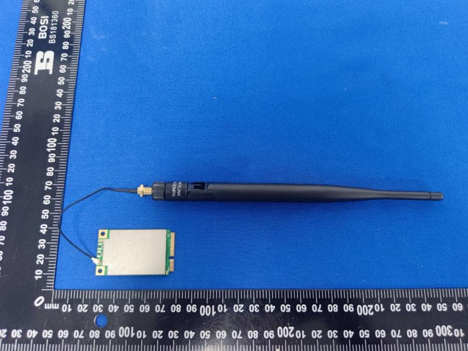
Click to zoom
Application Details
- Equipment Class
- DSS - Part 15 Spread Spectrum Transmitter
- Date of Grant
- Jan 05, 2023
- Application Purpose
- Original Equipment
- Date of Application
- Jan 05, 2023
- Equipment Note
- Linxdot Concentrator Module
- Frequency Range
- 902.30000000 - 914.90000000
- Company
- FX Technology Limited
- Country
- United Kingdom
Documents & Files
Document Text
Text extracted from the exhibit documents filed with the FCC. Open a document above to read the original.
Users Manual
LoRa Concentrator Module Linxdot LM-1001 Linxdot Concentrator Module Model Number: LM-1001 FCC ID: 2AUCLLM-1001 SN: LMAS220900058 Package contents Fx Technology Limited | www.linxdot.com Overview LM-1001 is a LoRa concentrator card with mini-PCIe form factor based on SX1302, which enables an easy integration into an existing router or other network equipment with LoRa Gateway capabilities. It can be used in any embedded platform offering a free mini-PCIe slot with SPI or USB connection. Furthermore, ZOE-M8Q GPS chip is integrated on board. LM-1001 is a complete and cost efficient LoRa gateway solution offering up to 10 programmable LM-1001 is a complete and cost efficient LoRa gateway solution offering up to 10 programmable parallel demodulation paths which are 8xSF5-SF12 LoRa demodulators, 8xSF5-SF10 LoRa demodulators, 125 /250 / 500 kHz LoRa demodulator and (G)FSK demodulator. It can detect at any time, any packet in a combination of 8 different spreading factors(SF5 to SF12) and 10 channels, and demodulate up to 16 packets at any time. It targets smart metering fixed networks and Internet-of-Things (IoT) applications, covering up to 500 nodes per square kilometer in an Main features Compatible with Mini PCI-e Edition specification with heat sink. SX1302 base band processor emulates 8 x8 channel LoRa packet detectors, 8 x SF5-SF12 LoRa demodulators, 8 x SF5-SF10 LoRa demodulators, one 125 /250 / 500 kHz high-speed LoRa demodulator and one (G)FSK demodulator . Optional built-in extra MCU to convert SPI interface of SX1302 to USB2. 0. Voltage of Mini PCI-e is 3.3 V, compatible with 3G/LTE card of Mini PCI-e type. Tx power up to 27dBm, Rx sensitivity down to -139dBm@SF12, BW 125 kHz. Tx power up to 27dBm, Rx sensitivity down to -139dBm@SF12, BW 125 kHz. Supports latest LoRaWAN 1.0.2 protocol. Supports global license-free frequency band (EU868, US915, AS923, AU915, KR920, IN865 and AS920). Supports optional SPI or USB interfaces. Built-in ZOE-M8Q GPS module. Optional LBT (Listen-Before-Talk) function. Fx Technology Limited | www.linxdot.com LoRa Concentrator Module Linxdot LM-1001 Specifications Pin configuration LoRa Concentrator Module Linxdot LM-1001 Fx Technology Limited | www.linxdot.com FCC Statement FCC standards: FCC CFR Title 47 Part 15 Subpart C Section 15.247 External Antenna with gain 2dBi(LoRa) FCC Regulatory Compliance: This device complies with Part 15 of the FCC Rules. Operation is subject to the following two conditions: (1) this device may not cause harmful interference, and (2) this device must accept any interference received, including interference that may cause undesired (2) this device must accept any interference received, including interference that may cause undesired operation. Note: This equipment has been tested and found to comply with the limits for a Class B digital device, Note: This equipment has been tested and found to comply with the limits for a Class B digital device, pursuant to Part 15 of the FCC Rules. These limits are designed to provide reasonable protection against harmful interference in a residential installation. This equipment generates, uses and can radiate radio frequency energy and, if not installed and used in accordance with the instructions, may cause harmful interference to radio communications. However, there is no guarantee that interference will not occur in a particular installation. If this equipment does cause harmful interference to radio or television reception, which can be If this equipment does cause harmful interference to radio or television reception, which can be determined by turning the equipment off and on, the user is encouraged to try to correct the interference by one or more of the following measures: -- Reorient or relocate the receiving antenna. -- Increase the separation between the equipment and receiver. -- Connect the equipment into an outlet on a circuit different from that to which the receiver is connected. -- Consult the dealer or an experienced radio/TV technician for help. -- Consult the dealer or an experienced radio/TV technician for help. Warning: changes or modifications not expressly approved by the party responsible for compliance could void the user’s authority to operate the equipment. time. It targets smart metering fixed networks If power exceeds the limit and the distance(Over 20cm distance in actual use between the device and user) is compliance with the requirement RF Exposure Compliance: This equipment complies with FCC radiation exposure limits set forth for an uncontrolled environment. This equipment complies with FCC radiation exposure limits set forth for an uncontrolled environment. This equipment should be installed and operated with a minimum distance of 20cm between the radiator and any part of your body. Notice to OEM integrator If the FCC ID is not visible when the module is installed inside another device, then the outside of the device into which the module is installed must also display a label referring to the enclosed module. The end product shall haves the words “Contains Transmitter Module FCC ID: 2AUCLLM-1001”. The device must be professionally installed. The device must be professionally installed. The intended use is generally not for the general public. It is generally for industry/commercial use. The connector is within the transmitter enclosure and can only be accessed by disassembly of the transmitter that is not normally required. The user has no access to the connector. Installation must be controlled. Installation requires special training. Any company of the host device which installs this modular with unlimited modular approval should Any company of the host device which installs this modular with unlimited modular approval should perform the test of radiated & conducted emission and spurious emission, etc. according to FCC part 15C: 15.247 , 15B Class B requirement, only if the tests result comply with FCC part 15C: 15.247 , 15B Class B requirement, then th…
Text truncated - open the document above for the full version.
Cover Letter(s)
Date: 12-23-2022 Office of Engineering Technology Federal Communications Commission 7435 Oakland Mills Road Columbia, MD 21046 USA Subject; Request for Confidentiality FCC ID: 2AUCLLM-1001 To Whom It May Concern, Pursuant to the provisions of the Commission’s rules Title 47 Sections §0.457 and §0.459, we are requesting the Commission to withhold the following attachment(s) as confidential documents from public disclosure indefinitely. These documents contain detailed system and equipment descriptions and are considered as proprietary information in operation of the equipment. The public disclosure of these documents might be harmful to our company and would give competitors an unfair advantage in the market. Schematic Diagram Block Diagram Parts List Operational Description Tune-up Procedure In additional to above mentioned documents, in order to comply with the marketing regulations in Title 47 CFR §2.803 and the importation rules in Title 47 CFR §2.1204, while ensuring that business sensitive information remains confidential until the actual marketing of newly authorized devices, we request Short Term Confidentiality of the following attachment(s); External Photos Test Setup Photos Internal Photos User Manual For 45 days, pursuant to Public Notice DA 04-1705. OR For 180 days pursuantto KDB 726920 D01. It is our understanding that all measurement test reports, FCC ID label format and correspondence during the certification review process cannot be granted as confidential documents and this information will be available for public review once the grant of equipment authorization is issued. Sincerely, Signature: Name: Liangchen Chen Title: Manager FX Technology Limited
Cover Letter(s)
FX Technology Limited Agent Authorization Company: FX Technology Limited Address: 2 Stone Buildings, Lincoln's Inn, London WC2A 3TH, United Kingdom Product Name: Linxdot Concentrator Module Model Number(s): LM-1001 Product Description: Linxdot Concentrator Module We authorize MiCOM Labs Inc., 575 Boulder Court, Pleasanton, California 94566, USA, to act on our behalf on all matters concerning the certification of above named equipment. We declare that MiCOM Labs Inc. is allowed to forward all information related to the approval and certification of equipment to the regulatory agencies as required and to discuss any issues concerning the approval application. Any and all acts carried out by MiCOM Labs on our behalf shall have the same effect as acts of our own. Signature:Date: 2022-12-23 Name: Liangchen Chen Title: Manager Company: FX Technology Limited
Cover Letter(s)
FX Technology Limited Federal Communications Commission Equipment Authorization Division 7435 Oakland Mills Road Columbia, MD 21046 USA Date: 2022-12-23 Subject: Modular Transmitter Application Company name: FX Technology Limited FCC ID: 2AUCLLM-1001 Dear Sir/Madam, This letter includes the FCC application requirements for Modular Transmitter Approval Request for;- FCC KDB 996369 D01 ‘Module Certification Guide v02; and FCC KDB 996369 D03 OEM Manual v01 In accordance with 47CFR 15.212 Modular Transmitters and KDB 996369 D01 ‘Module Equip Auth Guide v02’. FCC ID: 2AUCLLM-1001 has been examined against the following requirements. Requiremen t per 15.212 and KDB 996369 D01 Explanation from Grantee (do not write yes/no, but explain why product complies/how it is achieved) The radio elemen ts must have the radio frequency circuitry shielded. Physical components and tuning capacitor(s) may be located external to the shield, but must be on the module assembly. The modular have RF own shielding The module must have buffered modulation/data inputs to ensure that the device will comply with Part 15 requirements with any type of input signal. The modular transmitter have buffered modulation/data inputs The module must contai n power supply regulation on the module. The modular transmitter have its own power supply regulation. The module must contain a permanently attached antenna, or contain a unique antenna connector, and be marketed and operated only with specific antenna(s), per §§ 15.203, 15.204(b), 15.204(c), 15.212(a), 2.929(b). The modular has a External Antenna. T h e mod u le must d e mo nstrate compliance in a stand-alone configuration. The module compliance in a stand-alone configuration. The module must be labeled with its p ermanently affixed FCC ID label, or use an electronic display (see KDB Publication 784748). The FCC identification number can put on the modular with either a permanently affixed label The module must com ply with all specific rules applicable to the transmitter, including all the conditions provided in the integration instructions by the grantee. The instructions will be provided and apply to a complete transmitter and comply with specific rule. The module must comp ly with RF exposure requirements The total power density of modular transmitter final configuration comply with FCC RF Exposure FCC Modular Approval Request Rev 3.0 Date: 2022-12-23 Name: Liangchen Chen Title: Manager Signature of applicant
External Photos
Page 1 of 2 Appendix C: Photographs of EUT Product: Linxdot Concentrator Module Model: LM-1001 External Photos Antenna Page 2 of 2
ID Label/Location Info
Label Artwork and Location Model: LM-1001 Label: Location
Internal Photos
Page 1 of 1 Appendix C: Photographs of EUT Product: Linxdot Concentrator Module Model: LM-1001 Internal Photos
RF Exposure Info
Hotline: 400-6611-140 Tel: 86-755-27673339 Fax: 86-755-27673332 http://www.tct-lab.com TEST REPORT FCC ID. ............................ : 2AUCLLM-1001 Test Report No. ............... : TCT221205E905 Date of issue ................... : Dec. 27, 2022 Testing laboratory .......... : SHENZHEN TONGCE TESTING LAB Testing location/ address: 2101 & 2201, Zhenchang Factory Renshan Industrial Zone, Fuhai Subdistrict, Bao'an District, Shenzhen, Guangdong, 518103, People's Republic of China Applicant's name ............ : FX Technology Limited Address ........................... : 2 Stone Buildings, Lincoln's Inn, London WC2A 3TH, United Kingdom Manufacturer's name ... : FX Technology Limited Address ........................... : 2 Stone Buildings, Lincoln's Inn, London WC2A 3TH, United Kingdom Standard(s) ..................... : FCC CFR Title 47 Part 1.1307 KDB 447498 D04 Interim General RF Exposure Guidance v01 Product Name ................. : Linxdot Concentrator Module Trade Mark ...................... : Linxdot Model/Type reference ..... : LM-1001 Rating(s) ......................... : DC 3.3V Date of receipt of test item ......................................... : Dec. 05, 2022 Date (s) of performance of test ................................... : Jun. 08, 2022 - Dec. 27, 2022 Tested by (+signature) ... : Aaron MO Check by (+signature) .... : Beryl ZHAO Approved by (+signature): Tomsin General disclaimer: This report shall not be reproduced except in full, without the written approval of SHENZHEN TONGCE TESTING LAB. This document may be altered or revised by SHENZHEN TONGCE TESTING LAB personnel only, and shall be noted in the revision section of the document. The test results in the report only apply to the tested sample. Report No.: TCT221205E905 Page 2 of 6 Hotline: 400-6611-140 Tel: 86-755-27673339 Fax: 86-755-27673332 http://www.tct-lab.com Table of Contents 1. General Product Information ................................................................... 3 1.1. EUT description ..................................................................................................... 3 1.2. Model(s) list............................................................................................................ 3 2. General Information .................................................................................. 4 2.1. Test environment and mode ................................................................................. 4 2.2. Description of Support Units ................................................................................ 4 3. Facilities and Accreditations ................................................................... 5 3.1. Facilities ................................................................................................................. 5 3.2. Location ................................................................................................................. 5 4. Test Results and Measurement Data ...................................................... 6 Report No.: TCT221205E905 Page 3 of 6 Hotline: 400-6611-140 Tel: 86-755-27673339 Fax: 86-755-27673332 http://www.tct-lab.com 1. General Product Information 1.1. EUT description Product Name ....................... : Linxdot Concentrator Module Model/Type reference ........... : LM-1001 Sample Number....................: TCT221205E903-0101 Operation Frequency ........... : 125KHz: 902.3MHz~914.9MHz 500KHz: 923.3MHz~927.5MHz Modulation Type ................... : LoRa Antenna Type ........................ : External Antenna Antenna Gain ........................ : 2dBi Rating(s) ............................... : DC 3.3V Note: The antenna gain listed in this report is provided by applicant, and the test laboratory is not responsible for this parameter. 1.2. Model(s) list None. Report No.: TCT221205E905 Page 4 of 6 Hotline: 400-6611-140 Tel: 86-755-27673339 Fax: 86-755-27673332 http://www.tct-lab.com 2. General Information 2.1. Test environment and mode Item Normal condition Temperature +25ºC Voltage AC 120V/60Hz Humidity 56% Atmospheric Pressure: 1008 mbar Test Mode: Engineering mode: Keep the EUT in continuous transmitting by select channel 2.2. Description of Support Units The EUT has been tested as an independent unit together with other necessary accessories or support units. The following support units or accessories were used to form a representative test configuration during the tests. Equipment Model No. Serial No. FCC ID Trade Name / / / / / Note: 1. All the equipment/cables were placed in the worst-case configuration to maximize the emission during the test. 2. Grounding was established in accordance with the manufacturer’s requirements and conditions for the intended use. 3. For conducted measurements (Output Power, 20dB Occupied Bandwidth, Carrier Frequencies Separation, Hopping Channel Number, Dwell Time, Spurious Emissions), the antenna of EUT is connected to the test equipment via temporary antenna connector, the antenna connector is soldered on the antenna port of EUT, and the temporary antenna connector is listed in the Test Instruments. Report No.: TCT221205E905 Page 5 of 6 Hotline: 400-6611-140 Tel: 86-755-27673339 Fax: 86-755-27673332 http://www.tct-lab.com 3. Facilities and Accreditations 3.1. Facilities The test facility is recognized, certified, or accredited by the following organizations: ● FCC - Registration No.: 645098 SHENZHEN TONGCE TESTING LAB Designation Number: CN1205 The testing lab has been registered and fully described in a report with the (FCC) Federal Communications Commission. The acceptance letter from the FCC is maintained in our files. ● IC - Registration No.: 10668A-1 SHENZHEN TONGCE TESTING LAB CAB identifier: CN0031 The testing lab has been registered by Certification and Engineering Bureau of Industry Canada for radio equipment testing. 3.2. Location SHENZHEN TONGCE TESTING LAB Address: 2101 & 2201, Zhenchang Factory Renshan Industrial Zone, Fuhai Subdistrict, Bao'…
Text truncated - open the document above for the full version.
Test Report
Hotline: 400-6611-140 Tel: 86-755-27673339 Fax: 86-755-27673332 http://www.tct-lab.com TEST REPORT FCC ID. ............................ : 2AUCLLM-1001 Test Report No. ............... : TCT221205E903 Date of issue ................... : Dec. 27, 2022 Testing laboratory .......... : SHENZHEN TONGCE TESTING LAB Testing location/ address: 2101 & 2201, Zhenchang Factory Renshan Industrial Zone, Fuhai Subdistrict, Bao'an District, Shenzhen, Guangdong, 518103, People's Republic of China Applicant's name ............ : FX Technology Limited Address ........................... : 2 Stone Buildings, Lincoln's Inn, London WC2A 3TH, United Kingdom Manufacturer's name ... : FX Technology Limited Address ........................... : 2 Stone Buildings, Lincoln's Inn, London WC2A 3TH, United Kingdom Standard(s) ..................... : FCC CFR Title 47 Part 15 Subpart C Section 15.247 FCC KDB 558074 D01 15.247 Meas Guidance v05r02 ANSI C63.10:2013 Product Name ................. : Linxdot Concentrator Module Trade Mark ...................... : Linxdot Model/Type reference..... : LM-1001 Rating(s).......................... : DC 3.3V Date of receipt of test item ......................................... : Dec. 05, 2022 Date (s) of performance of test ................................... : Jun. 08, 2022 - Dec. 27, 2022 Tested by (+signature) ... : Aaron MO Check by (+signature) .... : Beryl ZHAO Approved by (+signature): Tomsin General disclaimer: This report shall not be reproduced except in full, without the written approval of SHENZHEN TONGCE TESTING LAB. This document may be altered or revised by SHENZHEN TONGCE TESTING LAB personnel only, and shall be noted in the revision section of the document. The test results in the report only apply to the tested sample. Report No.: TCT221205E903 Page 2 of 43 Hotline: 400-6611-140 Tel: 86-755-27673339 Fax: 86-755-27673332 http://www.tct-lab.com Table of Contents 1. General Product Information .................................................................. 3 1.1. EUT description ..................................................................................................... 3 1.2. Model(s) list ............................................................................................................ 3 1.3. Operation Frequency ............................................................................................ 4 2. Test Result Summary .............................................................................. 5 3. General Information ................................................................................. 6 3.1. Test environment and mode ................................................................................. 6 3.2. Description of Support Units ................................................................................ 6 4. Facilities and Accreditations .................................................................. 7 4.1. Facilities ................................................................................................................. 7 4.2. Location ................................................................................................................. 7 4.3. Measurement Uncertainty ..................................................................................... 7 5. Test Results and Measurement Data ..................................................... 8 5.1. Antenna requirement ............................................................................................ 8 5.2. Conducted Emission ............................................................................................. 9 5.3. Conducted Output Power ................................................................................... 13 5.4. 20dB Occupy Bandwidth .................................................................................... 15 5.5. Carrier Frequencies Separation ......................................................................... 18 5.6. Hopping Channel Number .................................................................................. 21 5.7. Dwell Time ............................................................................................................ 24 5.8. Pseudorandom Frequency Hopping Sequence ................................................ 27 5.9. Conducted Band Edge Measurement ................................................................ 28 5.10. Conducted Spurious Emission Measurement ................................................. 30 5.11. Radiated Spurious Emission Measurement .................................................... 32 Appendix A: Photographs of Test Setup Appendix B: Photographs of EUT Report No.: TCT221205E903 Page 3 of 43 Hotline: 400-6611-140 Tel: 86-755-27673339 Fax: 86-755-27673332 http://www.tct-lab.com 1. General Product Information 1.1. EUT description Product Name ....................... : Linxdot Concentrator Module Model/Type reference........... : LM-1001 Sample Number....................: TCT221205E903-0101 Operation Frequency ........... : 125KHz: 902.3MHz~914.9MHz Number of Channel .............. : 64 for FHSS Modulation Type ................... : LoRa Modulation Technology ....... : Hybrid system Antenna Type ........................ : External Antenna Antenna Gain ........................ : 2dBi Rating(s)................................ : DC 3.3V Note: The antenna gain listed in this report is provided by applicant, and the test laboratory is not responsible for this parameter. 1.2. Model(s) list None. Report No.: TCT221205E903 Page 4 of 43 Hotline: 400-6611-140 Tel: 86-755-27673339 Fax: 86-755-27673332 http://www.tct-lab.com 1.3. Operation Frequency 125KHz for FHSS Channel Frequency Channel Frequency Channel Frequency Channel Frequency 0 902.3MHz 16 905.5MHz 32 908.7MHz 48 911.9MHz 1 902.5MHz 17 905.7MHz 33 908.9MHz 49 912.1MHz 2 902.7MHz 18 905.9MHz 34 909.1MHz 50 912.3MHz 3 902.9MHz 19 906.1MHz 35 909.3MHz 51 912.5MHz 4 903.1MHz 20 906.…
Text truncated - open the document above for the full version.
Test Report
R & D Center:Room D 5 th Floor Building L,Block E ,71 Baocheng District ,Baoan District ,Shenzhen Factory:6 Floor,GangHuaXing Industrial Park,Rongshu Road 2 nd ,Fuyong,Baoan ,shenzhen Email:[email protected] Shenzhen SKYLink Technology Co.,Ltd Antenna Specification for Approval Customer Name: Product Name: LD-500 860-930MHZ Antenna Part NO.: SK860930D2B01A.JBB.SMAMF Write By: Damon Cui Issued Date: 2021-10-3 Customer R&D Dept Business Dept Approved By SKYLink R&D Dept Engineer Dept Approval Frequency Range VSWR Efficiency Peak Gain Impedance Polarization Dimension Antenna Color Radome Material Cable Type Connector Type Operation Temperature Storage Temperature Water proof Dustproof Anti-corrosion RoHs Compliant ANTENNAS AND SYSTERMS FOR TELEMATIC,MOBILE COMMUNICATION AND NAVIGATION HIGH PERFORMANCE MANUFACTURER ... MADE IN CHINA NO NO YES TPE RG178 RP-SMA Mechanical Data 195mm*13mm Black Environmental Data -40°C to 85°C -40°C to 85°C NO <2 >70% 2 dBi 50 Ohm Line FIBERGLAS ANTENNA MODEL:SK860930D2B01A.JBB.SMAMM Electronical Data 860~930 MHz www.tll-skylink.comE-MAIL:[email protected]@sina.com ANTENNAS AND SYSTERMS FOR TELEMATIC,MOBILE COMMUNICATION AND NAVIGATION HIGH PERFORMANCE MANUFACTURER ... MADE IN CHINA www.tll-skylink.comE-MAIL:[email protected]@sina.com
Test Setup Photos
Page 1 of 2 Appendix B: Photographs of Test Setup Product: Linxdot Concentrator Module Model: LM-1001 Radiated Emission Page 2 of 2 Conducted Emission
Contact Information
Applicant
Liangchen Chen
Technical Contact
Test Firm
SHENZHEN TONGCE TESTING LABBeryl Zhao
[email protected]+8675527208735
Technical Specifications
| # | Rule Parts | Frequency Range | Power Output |
|---|---|---|---|
| 1 | 15C | 902.3 MHz - 914.9 MHz | 150.70 mW |
Other Applications from FX Technology Limited
2AUCL-LD1001
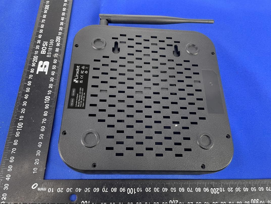
Feb 16, 2022Linxdot Hotspot
Equipment Class
DSS - Part 15 Spread Spectrum Transmitter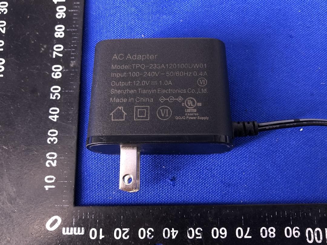
2AUCLLD-1000-1
Jul 26, 2021Router
Equipment Class
DSS - Part 15 Spread Spectrum Transmitter