2AUE82019X-BAND RADAR SYSTEM
Applied Physical Sciences Corp.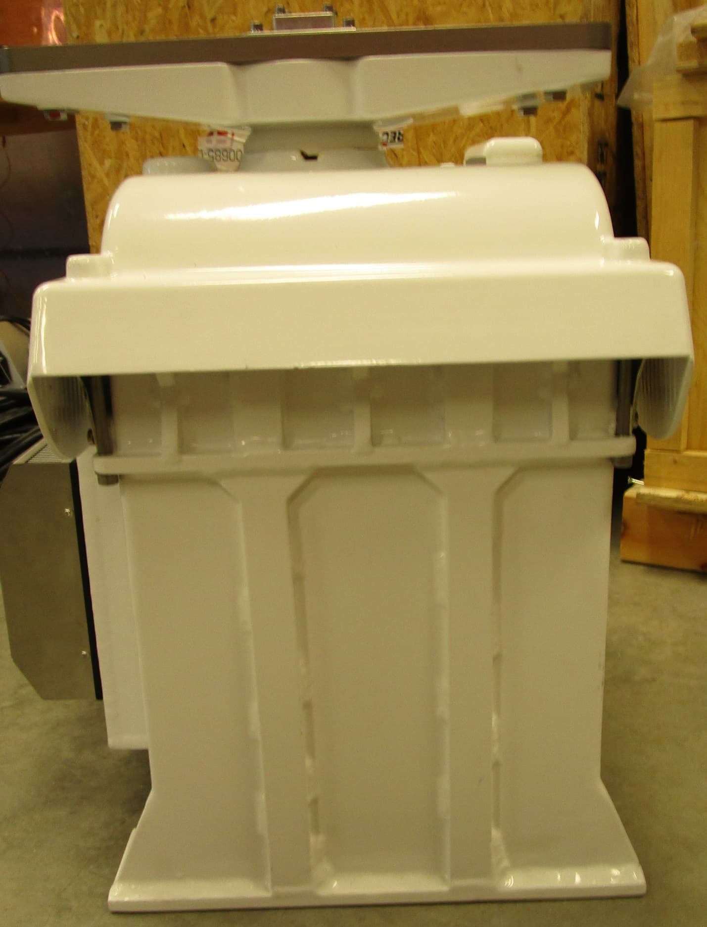
Click to zoom
Application Details
- Equipment Class
- MRD - Marine Radar
- Date of Grant
- Jan 16, 2020
- Application Purpose
- Original Equipment
- Date of Application
- Jan 16, 2020
- Equipment Note
- X-BAND RADAR SYSTEM
- Frequency Range
- 9300.00000000 - 9500.00000000
- Country
- United States
Documents & Files
Document Text
Text extracted from the exhibit documents filed with the FCC. Open a document above to read the original.
Users Manual
FutureWaves™ User Manual 12 December 2019 Document # U001-003-RPT-002 FutureWaves™ User Manual FutureWaves™ v1.7.0.1 1 RECORD OF CHANGES Revision Number Revision Date Description INITIALS - 12/02/2019 Initial DRAFT ML FutureWaves™ User Manual FutureWaves™ v1.7.0.1 2 Contents Overview ......................................................................................................................................... 3 System Description ......................................................................................................................... 3 Operating instructions ..................................................................................................................... 5 Startup ......................................................................................................................................... 5 Normal Operations ...................................................................................................................... 9 Planning ................................................................................................................................ 10 Timing ................................................................................................................................... 17 Data & Trends ....................................................................................................................... 24 Control & Settings ................................................................................................................ 25 Shut Down ................................................................................................................................ 35 Data Handling ............................................................................................................................... 36 Maintenance and Troubleshooting ................................................................................................ 37 Personnel Safety............................................................................................................................ 37 Appendix A - QuickStep ............................................................................................................... 38 Startup ................................................................................................................................... 38 Shutdown .............................................................................................................................. 40 Appendix B – Frequently Asked Questions.................................................................................. 42 Why is the FutureWaves™ heading different from the ships Gyro? .................................... 42 Why is the FutureWaves™ system unable to display any position? .................................... 42 Why is the depth displayed in FutureWaves™ different from the Fathometer? .................. 42 Why does the Ship Motion Sensor pitch/roll differ from my Clinometer? .......................... 43 Appendix C – System Information Data Sheet ............................................................................. 44 FutureWaves™ System Information ........................................................................................ 44 Appendix D – EU Declaration of Conformity .............................................................................. 46 Appendix E – FCC Regulation Statements ................................................................................... 47 FutureWaves™ User Manual FutureWaves™ v1.7.0.1 3 Overview This document serves as a guide for operating the FutureWaves™ system. FutureWaves™ is a system with the capability to measure, predict, and display the environmental and ship motion parameters needed for operators to safely conduct operations. The system provides accurate ship motion and wave forecasting for time scales of interest (~5 minutes) in up to sea state 5 and ship speeds of up to 10 knots. System Description Figure 1: FutureWaves™ Components and Physical Layout The major hardware subsystems of the FutureWaves™ system are: User Workstation [Bridge Console] – The User Workstation (UWS) is a ruggedized Intel PC running Windows 10 that provides the main interface for FutureWaves™. Detailed software description is in the following section. Primary Processing Unit (PPU) – The PPU is a ruggedized Intel PC running Linux Ubuntu 16.04. It performs the core algorithms of FutureWaves™ taking in sensor data and providing products to the UWS. The PPU is in the Electronics Locker located in the Bosun’s Storeroom below the forecastle deck. Wave Radar Unit (WRU) – The WRU is the principal FutureWaves™ sensor for measuring the oceanic wave field. It is a modified marine navigation radar specialized for ocean surface return. Radar control and signal processing are performed by a Wave Radar Unit FutureWaves™ User Manual FutureWaves™ v1.7.0.1 4 dedicated Radar Processing Unit (RPU) consisting of an Intel PC with Windows 10. The CORR is on the foremast and the RPU is also within the Electronics Locker. Ship Motion Sensor (SMS) – Real-time ship motion is provided to the system by an OXTS RT2502 IMU. The sensor uses accelerometers and gyros in conjunction with dual antenna GPS with L1 carrier-phase differencing. The SMS is located in the Electronics Locker and connects to the PPU via a direct Ethernet connection. GPS antennas are located on the foremast. Meteorological (MET) Sensor – Real-time environmental data (e.g. wind speed/direction, temperature) is provided to the system by a Gill® MetPak™ II Weather Station via a RS- 422 serial connection to the PPU. The MET sensor is located on the foremast. Ethernet network switch – The processors are networked using a Dell PowerConnect 2816 16-port, high-performance Gigabit Ethernet switch also located within the Electronics Locker. The three processor components (PPU, RPU, and UWS) are all Cinco…
Text truncated - open the document above for the full version.
Attestation Statements
Applied Physical Sciences Corp. 475 Bridge Street, Suite 100, Groton, CT 06340 (860) 448-3253 · www.aphysci.com 14 November 2019 Federal Communications Commission Authorization and Evaluation Division 7435 Oakland Mills Road Columbia, MD 21046 Subject: Application for Certification for FCC ID 2AUE82019 FCC Rules, Part 90.203(e) and (g) To Whom It May Concern: The equipment related to the subject application meets the requirements of the FCC Rules, Part 90.203(e) and (g), as applicable. Programming of this product’s transmit frequencies can be performed ONLY by the manufacturer or by service or maintenance personal. The operator cannot be program transmit frequencies using the equipment’s external operation controls.. Very truly yours, David Horne Sr. Vice President Business Manager let: FCC:11-14-19-02
Cover Letter(s)
Applied Physical Sciences Corp. 475 Bridge Street, Suite 100, Groton, CT 06340 (860) 448-3253 · www.aphysci.com 14 November 2019 Federal Communications Commission Authorization and Evaluation Division 7435 Oakland Mills Road Columbia, MD 21046 Subject: Confidentiality Request Regarding Application for Certification for FCC ID 2AUE82019 To Whom It May Concern: Pursuant to Sections 0.457 and 0.459 of the Commission’s Rules, Applied Physical Sciences Corp. hereby request confidential treatment of information accompanying this application as outlined below: Exhibit Type Schematics Block Diagram Circuit Description Parts List Tuning Procedure The above materials contain trade secrets and proprietary information not customarily released to the public. The public disclosure of these materials may be harmful to the applicant and provide unjustified benefits to its competitors. The applicant understands that pursuant to Section 0.457 of the Rules, disclosure of this application and all accompanying documentation will not be made before the date of the Grant for this application. Very truly yours, David Horne Sr. Vice President Business Manager let: FCC:11-14-19-01
Cover Letter(s)
Applied Physical Sciences Corp. 475 Bridge Street, Suite 100, Groton, CT 06340 (860) 448-3253 · www.aphysci.com 05 November 2019 Timco Engineering, Inc. 849 N.W. State Road 45 P.O. Box 370 Newberry, FL 32669 Subject: Application(s) for Certification for FCC ID 2AUE82019 To Whom It May Concern: Applied Physical Sciences Corp. (APS) hereby authorizes Sharon Hoffman at TIMCO ENGINEERING, INC. on its behalf, to apply for certification on our equipment referenced above. Any and all acts carried out by TIMCO ENGINEERING, INC. on our behalf shall have the same effect as acts of our own. This is to advise that we are in full compliance with the Anti- Drug Abuse Act. We, the applicant, are not subject to a denial of federal benefits pursuant to Section 5301 of the Anti-Drug Act of 1988, 21 USC853a, and no party to the application is subject to a denial of federal benefits pursuant to that section. Very truly yours, David Horne Sr. Vice President Business Manager let: TIMCO:11-05-19-01
External Photos
APPLICANT: APPLIED PHYSICAL SCIENCES CORP. FCC ID: 2AUE82019 EXTERNAL PHOTOS FRONT VIEW REAR VIEW REAR/SIDE VIEW RIGHT SIDE VIEW LEFT SIDE VIEW
ID Label/Location Info
FCC/CE Label Placement Diagram Applied Physical Sciences Corp. 475 Bridge Street, Suite 100, Groton, CT 06340 (860) 448-3253 · www.aphysci.com W AVE - I 1.00 S IDE P ANEL L ABEL P LACEMENT D IAGRAM Place Label Here
ID Label/Location Info
FutureWaves Wave-i 1.00 FCC ID: 2AUE82019
Internal Photos
APPLICANT: APPLIED PHYSICAL SCIENCES CORP. FCC ID: 2AUE82019 INTERNAL PHOTOS SP ERRY-TRIGGER BOARD – FRONT VIEW SP ERRY-TRIGGER BOARD – BACK VIEW SPERRY-MODULATOR – FRONT VIEW SPERRY-TRIGGER – BACK VIEW SPERRY- PSU BOARD – FRONT VIEW SPERRY- PSU BOARD –REAR VIEW PELTIER-COOLER – HEATER – FRONT VIEW PELTIER-COOLER – HEATER – REAR VIEW PELTIER-COOLER-CONTROLLER FRONT VIEW PELTIER-COOLER-CONTROLLER BACK VIEW MA GNETRON – FRONT VIEW MA GNETRON – BACK VIEW CONTROLLER – FRONT VIEW CONTROLLER – BACK VIEW PC IE – RECEIVER – FRONT VIEW PCIE RECEIVER – BACK VIEW STALO – X-BAND – FRONT VIEW STALO – X-BAND – BACK VIEW SPU-I O BOARD – TOP VIEW SPU-I O BOARD – BOTTOM VIEW APS-500-CLK – TOP VIEW APS-500-CLK – BOTTOM VIEW IFD-PSU TOP VIEW IFD-PSU – BACK VIEW REF-O SC-100 – TOP VIEW REF-O SC-100 – BOTTOM VIEW APS – PSU – TOP VIEW APS – PSU – BOTTOM VIEW AP S-AC-FILTER – TOP VIEW AP S-AC-FILTER – BACK VIEW VIEW MT U – BEARING – TOP VIEW MTU- BEARING – BOTTOM VIEW MTU – CONTROLLER – TOP VIEW MTU-CONTROLLER – BOTTOM VIEW MT U – IO – FRONT VIEW MT U – IO – BOTTOM VIEW COM-SWITCH – IO – TOP VIEW COM-SWITCH – IO – BOTTOM VIEW DOWN CONVERTER – TOP VIEW DOWN CONVERTER – BOTTOM VIEW
RF Exposure Info
Applied Physical Sciences Corp. 475 Bridge Street, Suite 100, Groton, CT 06340 (860) 448-3253 · www.aphysci.com APS Proprietary Information This document may not be shared in part or in whole without the expressed written permission of Applied Physical Sciences, Corp. X-band Wave Radar Radiation Hazards to Personnel FutureWaves™ Wave-i 1.00 RF Exposure Statements 26 November 2019 APS Document Number: U001-003-RPT-001 Submitted by: J. Kusters Technical Contact: John Kusters Applied Physical Sciences Corp. 7525 Metropolitan Drive Suite 306 San Diego CA 92108 Phone: (619) 994-4934 Email: [email protected] Administrative Business Contact: Shawn Singer Applied Physical Sciences Corp. 475 Bridge Street, Suite 100 Groton, CT 06340 Phone: (860) 448-3253 x 157 Fax: (860) 448-3075 Email: [email protected] Document Revision History Revision Description Author Date 1.0 Initial Draft John Kusters 26 NOV 2019 1. Overview This document addresses the potential hazard to personnel of using X-band radar and recommended mitigations to reduce risk of that hazard. Specific direction to mitigate this hazard is provided per each unique FutureWaves™ installation. This document serves as a general overview of the RF exposure risks and RF Exposure Safety Distances. The antenna gain used with this transmitter should be 28 dBi or less and all persons should maintain a minimum safety separation distance of 35cm while functioning properly. Applied Physical Sciences Corp. 475 Bridge Street, Suite 100, Groton, CT 06340 (860) 448-3253 · www.aphysci.com APS Proprietary Information This document may not be shared in part or in whole outside of Heerema Marine Contractors without the expressed written permission of Applied Physical Sciences, Corp. Page 1 of 3 2. Background Various organizations and countries have developed exposure standards for radio frequency (RF) energy. These standards recommend safe levels of exposure for both the general public and for workers. In the United States, the Federal Communications Commission (FCC) has adopted and used recognized safety guidelines for evaluating RF environmental exposure since 1985. The FCC guidelines for human exposure to RF fields were derived from the recommendations of two expert organizations, the National Council on Radiation Protection and Measurements (NCRP) and the Institute of Electrical and Electronics Engineers (IEEE). Expert scientists and engineers developed both the NCRP exposure criteria and the IEEE standard after extensive reviews of the scientific literature related to RF biological effects. The exposure guidelines are based on thresholds for known adverse effects, and they incorporate appropriate margins of safety. Many countries in Europe and elsewhere use exposure guidelines developed by the International Commission on Nonionizing Radiation Protection (ICNIRP). The ICNIRP safety limits are generally similar to those of the NCRP and IEEE, with a few exceptions. The NCRP, IEEE, and ICNIRP exposure guidelines state the threshold level at which harmful biological effects may occur, and the values for maximum permissible exposure (MPE) recommended for power density are based on this threshold level. The industrial specifications set for radiation hazard to personnel are contained in ANSI/IEEE C95.1-2005 (IEEE Standard for Safety Levels with Respect to Human Exposure to Radio Frequency Electromagnetic Fields, 3 kHz to 300 GHz) and the United States Federal Communications Commission (FCC) Title 47 Section 1.1310 – Radiofrequency radiation exposure limits. Per these references the occupational/controlled MPE limits for an X-band (8.0 to 12.0 GHz) radar is a power density of 5 mW/cm 2 for a 6 minute averaging time. Occupational/Controlled MPE limits apply in situations in which persons are exposed as a consequence of their employment provided those persons are fully aware of the potential for exposure and can exercise control over their exposure. These MPE recommendations are made to protect against established adverse health effects in human beings associated with exposure to electric, magnetic and electromagnetic fields in the frequency range of 3 kHz to 300 GHz. The recommendations are expressed in terms of basic restrictions (BRs) and MPE values. The BRs are limits on internal fields, specific absorption rate (SAR), and current density; the MPEs, which are derived from the BRs, are limits on external fields and induced and contact current. The recommendations, which protect against effects associated with electrostimulation and tissue and whole-body heating, are intended to apply to all human exposures except for exposure of patients by, or under the direction of, physicians and medical professionals. These recommendations are not intended for the purpose of preventing interference with medical and other devices that may exhibit susceptibility to RF fields. Using the MPE limit an effective safety zone around the radar transmitters can be determined and a boundary established to reduce risk of excessive exposure. To calculate this safety zone APS used IEEE Std C95.3™-2002 (R2008) - Recommended Practice for Measurements and Computations of Radio Frequency Electromagnetic Fields With Respect to Human Exposure to Such Fields, 100 kHz–300 GHz. In determining the safety zone for a radar system a number of factors affecting the RF power density must be considered: Applied Physical Sciences Corp. 475 Bridge Street, Suite 100, Groton, CT 06340 (860) 448-3253 · www.aphysci.com APS Proprietary Information This document may not be shared in part or in whole outside of Heerema Marine Contractors without the expressed written permission of Applied Physical Sciences, Corp. Page 2 of 3 Radar systems send electromagnetic waves in pulses and not continuously. This makes the average power emitted much lower than the peak pulse power. Radars are directional and the RF energy they generate is contained in beams that are very narrow and resemble the beam of a spotlight.…
Text truncated - open the document above for the full version.
Test Report
849 NW STATE ROAD 45 PHONE: 352.472.5500 NEWBERRY, FL 32669 USA EMAIL: [email protected] WEB: HTTP://WWW.TIMCOENGR.COM An IIA Company FCC CFR 47 Part 80 Radar Test Report APPLICANT APPLIED PHYSICAL SCIENCES CORP. ADDRESS 475 BRIDGE STREET GROTON CT 06340 USA FCC ID 2AUE82019 MODEL NUMBER FutureWaves Wave-i 1.00 PRODUCT DESCRIPTION X- BAND RADAR SYSTEM DATE SAMPLE RECEIVED 08/27/2019 FINAL TEST DATE 09/10/2019 TESTED BY Franklin Rose APPROVED BY Tim Royer TEST RESULTS ☒ PASS ☐ FAIL Report Number Report Version Description Issue Date 2280AUT19_PT80 Radar TestReport_ Rev1 Initial Issue 09/18/2019 This report shall not be reproduced except in full without the written approval of Timco Engineering, Inc. This report relates only to the sample(s) tested. TABLE OF CONTENTS GENERAL REMARKS ........................................................................................................................................... 2 T ESTING INFORMATION .......................................................................................................................................... 3 O PERATING FREQUENCIES ....................................................................................................................................... 4 SUMMARY OF TESTING ...................................................................................................................................... 5 MODULATION CHARACTERISTICS ..................................................................................................................... 6 FCC BANDWIDTH ................................................................................................................................................. 6 PULSE CHARACTERISTICS ................................................................................................................................. 7 P ULSE CHARACTERISTICS TABLE ............................................................................................................................... 7 O PERATIONAL MODE(S) TABLE ................................................................................................................................. 7 RF POWER OUTPUT ........................................................................................................................................... 8 T EST DATA: MODE 1, MEAN POWER OUTPUT ........................................................................................................... 8 T EST DATA: POWER AT THE FINAL AMPLIFIER .......................................................................................................... 9 OCCUPIED BANDWIDTH .................................................................................................................................. 10 99% OCCUPIED BANDWIDTH RULE PARTS ................................................................................................................. 10 40 DB OCCUPIED BANDWIDTH RULE PARTS ................................................................................................................ 11 T EST DATA: OCCUPIED BANDWIDTH MEASUREMENT TABLE ........................................................................................ 11 T EST DATA: MODE 1 99% OBW PLOT ................................................................................................................ 12 T EST DATA: MODE 1 40DB OBW PLOT ............................................................................................................... 13 EMISSION MASK ............................................................................................................................................. 14 T EST DATA: MODE 1 EMISSION MASK B PLOT ....................................................................................................... 15 SPURIOUS EMISSIONS AT ANTENNA TERMINAL (CONDUCTED) ...................................................................... 16 B ANDWIDTH COMPENSATION CALCULATION TABLE ........................................................................................................ 18 T EST DATA: MODE 1, 2 ND HARMONIC PLOT ........................................................................................................... 19 T EST DATA: MODE 1, 3 RD HARMONIC PLOT ........................................................................................................... 20 T EST DATA: MODE 1, 4 TH HARMONIC PLOT ........................................................................................................... 21 FIELD STRENGTH OF SPURIOUS EMISSIONS ................................................................................................... 22 B ANDWIDTH COMPENSATION CALCULATION TABLE ........................................................................................................ 25 T EST DATA: MODE 1, RADIATED SPURIOUS EMISSIONS PLOT ..................................................................................... 26 T EST DATA: MODE 1, RADIATED SPURIOUS EMISSIONS TABLE ................................................................................... 26 FREQUENCY STABILITY ................................................................................................................................... 27 STATEMENT OF MEASUREMENT UNCERTAINTY ................................................................................................ 30 EMC EQUIPMENT LIST ..................................................................................................................................... 31 Applicant: APPLIED PHYSICAL SCIENCES CORP. FCC ID: 2AUE82019 Report: 2280AUT19_PT80 Radar TestReport_Rev1 Page 2 of 31 GENERAL REMARKS Summary The device under test does: ☒ Fulfill the general approval requirements as identified in this test report and was selected by the customer. ☐ Not fulfill the general approval requirements as identified in this test report Attestations This equipment has been te…
Text truncated - open the document above for the full version.
Test Report
849 NW STATE ROAD 45 PHONE: 352.472.5500 NEWBERRY, FL 32669 USA EMAIL: [email protected] WEB: HTTP://WWW.TIMCOENGR.COM An IIA Company FCC CFR 47 Part 90 Radar Test Report APPLICANT APPLIED PHYSICAL SCIENCES CORP. ADDRESS 475 BRIDGE STREET GROTON CT 06340 USA FCC ID 2AUE82019 MODEL NUMBER FutureWaves Wave-i 1.00 PRODUCT DESCRIPTION X- BAND RADAR SYSTEM DATE SAMPLE RECEIVED 08/27/2019 FINAL TEST DATE 09/10/2019 TESTED BY Franklin Rose APPROVED BY Tim Royer TEST RESULTS ☒ PASS ☐ FAIL Report Number Report Version Description Issue Date 2280AUT19_PT90 Radar TestReport_ Rev1 Initial Issue 09/18/2019 This report shall not be reproduced except in full without the written approval of Timco Engineering, Inc. This report relates only to the sample(s) tested. TABLE OF CONTENTS GENERAL REMARKS ........................................................................................................................................... 2 T ESTING INFORMATION .......................................................................................................................................... 3 O PERATING FREQUENCIES ....................................................................................................................................... 4 SUMMARY OF TESTING ...................................................................................................................................... 5 MODULATION CHARACTERISTICS ..................................................................................................................... 6 FCC BANDWIDTH ................................................................................................................................................. 6 PULSE CHARACTERISTICS ................................................................................................................................. 7 P ULSE CHARACTERISTICS TABLE ............................................................................................................................... 7 O PERATIONAL MODE(S) TABLE ................................................................................................................................. 7 RF POWER OUTPUT ........................................................................................................................................... 8 T EST DATA: MODE 1, MEAN POWER OUTPUT ........................................................................................................... 8 T EST DATA: POWER AT THE FINAL AMPLIFIER .......................................................................................................... 9 OCCUPIED BANDWIDTH .................................................................................................................................. 10 99% OCCUPIED BANDWIDTH RULE PARTS ................................................................................................................. 10 40 DB OCCUPIED BANDWIDTH RULE PARTS ................................................................................................................ 11 T EST DATA: OCCUPIED BANDWIDTH MEASUREMENT TABLE ........................................................................................ 11 T EST DATA: MODE 1 99% OBW PLOT ................................................................................................................ 12 T EST DATA: MODE 1 40DB OBW PLOT ............................................................................................................... 13 EMISSION MASK ............................................................................................................................................. 14 T EST DATA: EMISSION MASK CALCULATIONS ........................................................................................................ 15 T EST DATA: MODE 1 EMISSION MASK B PLOT ....................................................................................................... 16 T EST DATA: MODE 1 EMISSION MASK C PLOT ....................................................................................................... 17 SPURIOUS EMISSIONS AT ANTENNA TERMINAL (CONDUCTED) ...................................................................... 18 B ANDWIDTH COMPENSATION CALCULATION TABLE ........................................................................................................ 20 T EST DATA: MODE 1, 2 ND HARMONIC PLOT ........................................................................................................... 21 T EST DATA: MODE 1, 3 RD HARMONIC PLOT ........................................................................................................... 22 T EST DATA: MODE 1, 4 TH HARMONIC PLOT ........................................................................................................... 23 FIELD STRENGTH OF SPURIOUS EMISSIONS ................................................................................................... 24 B ANDWIDTH COMPENSATION CALCULATION TABLE ........................................................................................................ 27 T EST DATA: MODE 1, RADIATED SPURIOUS EMISSIONS PLOT ..................................................................................... 28 T EST DATA: MODE 1, RADIATED SPURIOUS EMISSIONS TABLE ................................................................................... 28 FREQUENCY STABILITY ................................................................................................................................... 29 STATEMENT OF MEASUREMENT UNCERTAINTY ................................................................................................ 32 EMC EQUIPMENT LIST ..................................................................................................................................... 33 Applicant: APPLIED PHYSICAL SCIENCES CORP. FCC ID: 2AUE82019 Report: 2280AUT19_PT90 Radar TestReport_Rev1 Page…
Text truncated - open the document above for the full version.
Test Setup Photos
Applicant: APPLIED PHYSICAL SCIENCES CORP. FCC ID: 2AUE82019 Conducted Measurements TEST SETUP PHOTOGRAPHS Radiated Measurements: Table Setup, Front TEST SETUP PHOTOGRAPHS Radiated Measurements: Table Setup, Rear TEST SETUP PHOTOGRAPHS Field Strength of Spurious Emissions 30 MHz to 200 MHz (Biconical Antenna) TEST SETUP PHOTOGRAPHS Field Strength of Spurious Emissions 200 MHz to 1 GHz (Log Periodic Antenna) TEST SETUP PHOTOGRAPHS Field Strength of Spurious Emissions 1 – 18 GHz (Dual Ridge Waveguide Antenna) TEST SETUP PHOTOGRAPHS Field Strength of Spurious Emissions > 18 GHz (Double Ridge Horn Antenna) TEST SETUP PHOTOGRAPHS Frequency Stability
Test Setup Photos
Applicant: APPLIED PHYSICAL SCIENCES CORP. FCC ID: 2AUE82019 Conducted Measurements TEST SETUP PHOTOGRAPHS Radiated Measurements: Table Setup, Front TEST SETUP PHOTOGRAPHS Radiated Measurements: Table Setup, Rear TEST SETUP PHOTOGRAPHS Field Strength of Spurious Emissions 30 MHz to 200 MHz (Biconical Antenna) TEST SETUP PHOTOGRAPHS Field Strength of Spurious Emissions 200 MHz to 1 GHz (Log Periodic Antenna) TEST SETUP PHOTOGRAPHS Field Strength of Spurious Emissions 1 – 18 GHz (Dual Ridge Waveguide Antenna) TEST SETUP PHOTOGRAPHS Field Strength of Spurious Emissions > 18 GHz (Double Ridge Horn Antenna) TEST SETUP PHOTOGRAPHS Frequency Stability
Contact Information
Applicant
David Horne(Sr. Vice President / Business Manager)
Test Firm
Timco Engineering, Inc.Bruno Clavier
Technical Specifications
| # | Rule Parts | Frequency Range | Power Output | Emission | Tolerance |
|---|---|---|---|---|---|
| 1 | 80,90 | 9.30 GHz - 9.50 GHz | 501.19 W | 144MP0N | 0.0150000000 % |