2AUGK-HI764113Rugged Optical Dissolved Oxygen Probe for Fresh and Saltwater Applications
Hanna Instruments, Inc.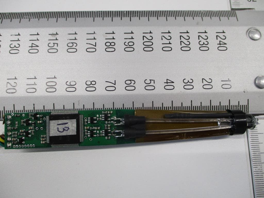
Click to zoom
Application Details
- Equipment Class
- DXX - Part 15 Low Power Communication Device Transmitter
- Date of Grant
- Nov 18, 2020
- Application Purpose
- Original Equipment
- Date of Application
- Nov 05, 2020
- Equipment Note
- Rugged Optical Dissolved Oxygen Probe for Fresh and Saltwater Applications
- Frequency Range
- 13.56000000 - 13.56000000
- Company
- Hanna Instruments, Inc.
- Country
- United States
Documents & Files
Document Text
Text extracted from the exhibit documents filed with the FCC. Open a document above to read the original.
Users Manual
INSTRUCTION MANUAL HI98198 opdo ® Optical Dissolved Oxygen Meter All rights are reserved. Reproduction in whole or in part is prohibited without the written consent of the copyright owner, Hanna Instruments Inc., Woonsocket, Rhode Island, 02895, USA. Thank you for choosing a Hanna Instruments product. Please read this instruction manual carefully before using this meter. This manual will provide you with the necessary information for correct use of this meter, as well as a precise idea of its versatility. If you need additional technical information, do not hesitate to e‑mail us at [email protected] or view our worldwide contact list at www.hannainst.com. Dear Customer, 3 3 TABLE OF CONTENTS TABLE OF CONTENTS 1. PRELIMINARY EXAMINATION ...............................................................................................4 2. GENERAL DESCRIPTION .......................................................................................................5 3. FUNCTIONAL DESCRIPTION ..................................................................................................6 4. SPECIFICATIONS .................................................................................................................7 5. THEORY OF OPERATION ......................................................................................................9 6. PROBE COMPONENTS .......................................................................................................10 7. INITIAL PREPARATION .......................................................................................................11 8. SETUP .............................................................................................................................13 8.1. PARAMETER SCREENS .............................................................................................15 9. CALIBRATION ...................................................................................................................26 9.1. DO CALIBRATION ....................................................................................................26 9.2. PRESSURE CALIBRATION .........................................................................................30 9.3. TEMPERATURE CALIBRATION ...................................................................................31 10. GOOD LABORATORY PRACTICE (GLP) .................................................................................33 11. MEASUREMENT ..............................................................................................................34 12. LOGGING ........................................................................................................................35 12.1. LOGGING THE CURRENT DATA ................................................................................35 12.2. VIEW LOGGED DATA ..............................................................................................35 13. RETRIEVING DATA ...........................................................................................................37 13.1. METER TO PC ........................................................................................................37 13.2. METER TO USB DRIVE ...........................................................................................37 14. DO MEASUREMENT.........................................................................................................39 15. BOD MEASUREMENT ......................................................................................................40 16. OUR MEASUREMENT ......................................................................................................45 17. BATTERY REPLACEMENT ..................................................................................................50 18. PROBE MAINTENANCE ....................................................................................................51 19. TROUBLESHOOTING GUIDE .............................................................................................54 20. ACCESSORIES .................................................................................................................55 CERTIFICATION ......................................................................................................................56 RECOMMENDATIONS FOR USERS ............................................................................................56 WARRANTY ...........................................................................................................................57 4 PRELIMINARY EXAMINATION 1. PRELIMINARY EXAMINATION Remove the instrument and accessories from the packaging and examine it carefully. For further assistance, please contact your local Hanna Instruments Office or email us at [email protected]. Each HI98198 opdo ® is supplied in a custom thermoformed durable carrying case with: • HI764113 Optical DO probe with built-in temperature sensor, protective shield and 4 m (13’4) cable • HI764113-1 Smart Cap with o-ring • HI7040 Bicomponent Zero Oxygen Solution • Calibration/storage vessel • 100 mL plastic beaker (2 pcs.) • 6 g sachet with silicone grease • Syringe • Lens wipe (1 pc.) • 1.5V AA batteries (4 pcs.) • Instrument quality certificate • Probe quality certificate • DO Smart Cap quality certificate • USB Type A to C cable • Instruction manual Note: Save all packing material until you are sure that the instrument works correctly. Any damaged or defective item must be returned in its original packing material with the supplied accessories. 5 GENERAL DESCRIPTION 2. GENERAL DESCRIPTION The HI98198 opdo ® meter is a rugged, portable dedicated dissolved oxygen (DO) meter designed for fresh and saltwater measurements of dissolved oxygen. This professional, waterproof meter complies with IP67 standards and measures DO, barometric pressure, and temperature. The HI98198 opdo meter is only compatible with HI764113 dig…
Text truncated - open the document above for the full version.
Internal Photos
SIQ Ljubljana, Tržaška cesta 2, SI-1000 Ljubljana, Slovenia T +386 1 4778 100, F +386 1 4778 444, [email protected], www.siq.si Internal photos Project file: C20182180 Date: 2019-05-23 Pages: 5 Product: Optical DO probe Type reference: HI764113 Page: 2 (5) Figure 1 Figure 2 Page: 3 (5) Figure 3 Figure 4 Page: 4 (5) Figure 5 Figure 6 Page: 5 (5) Figure 7 Figure 8
Test Report
T251-0384/19 Page: 2 (55) CONTENTS page 1 GENERAL 3 1.1 EQUIPMENT UNDER TEST 3 1.2 ANSI C63.4 SUBPART SELECTION 7 1.3 CLASS STATEMENT REQUIREMENTS 7 1.4 OCCUPIED BANDWIDTH MEASUREMENT 7 1.5 QUASI-PEAK DETECTOR 7 1.6 PEAK, RMS, AND AVERAGE DETECTORS 7 2 LIMITS FOR ALL SUBPARTS 8 2.1 SUBPART C: INTENTIONAL RADIATORS 8 3 ALL TEST EQUIPMENT AND THEIR DESCRIPTION 9 3.1 GENERAL INFORMATION 9 3.2 OTHER INSTRUMENT INFORMATION AND AUXILIARY EQUIPMENT 10 4 CONVERSION FACTORS AND ALL OTHER FORMULAS 30 5 GENERAL AND SPECIAL CONDITIONS DESCRIPTION 31 5.1 GENERAL CONDITION DESCRIPTION 31 5.2 SPECIAL CONDITION DESCRIPTION 34 6 TEST SUMMARY 35 6.1 OPERATING VOLTAGES/FREQUENCIES USED FOR TESTING 35 7 EMISSION TESTS 36 7.1 CONDUCTED EMISSION MEASUREMENT (15.207) 36 7.2 RADIATED EMISSION MEASUREMENT (15.209) 38 7.3 BANDWIDTH OF THE EMISSION (15.215) 48 7.4 SPECTRUM MASK (15.225) 52 7.5 FREQUENCY TOLERANCE OF THE CARRIER SIGNAL (15.225) 54 T251-0384/19 Page: 3 (55) 1 GENERAL History sheet Date Report No. Change Revision 2019-05-06 T251-0384/19 Initial Test Report issued. -- Environmental conditions: Ambient temperature: 15C to 35C Relative humidity: 30% to 60% Atmospheric pressure: 860 mbar to 1060 mbar Places of manufacture: 1. HANNA INSTRUMENTS Inc. Highland Industial Park, 584 Park East Drive Woonsocket, RI 02895 USA 2. SC HANNA INSTRUMENTS SRL Hanna street number 1, RO-457260 Nusfalau, Judetul Salaj, Romania 1.1 Equipment under test Optical DO probe Type: HI764113 Tested SIQ sample number: S20187559 T251-0384/19 Page: 4 (55) Copy of markings: T251-0384/19 Page: 5 (55) 1.1.1 General product information The Hanna digital dissolved oxygen probe HI764113 is compatible with the HI98198 opdo™ meter. The HI98198 opdo™ meter is a portable dedicated dissolved oxygen (DO) meter designed for fresh and saltwater measurements of dissolved oxygen. This professional, waterproof meter measures DO, barometric pressure, and temperature. The HI98198 is supplied with a HI764113 digital optical dissolved oxygen probe. The opdo probe uses a smartcap platinum based luminescent compound coated sensor with a built-in RFID for transferring factory calibration coeffiicents and to monitor the time from first use in order to alert the user when to replace on a yearly basis Software version: / Firmware version: v1.01 SIQ tested number: S20187559 Serial number: 11223344 (726CC990500104E0) Dimensions of EUT (LxWxD) / mm: 174 x 25 x 25 (with guard) Grounding: / Floor standing / table-top equipment or a combination: Table-top Electromagnetic environment: Industrial electromagnetic environment Highest Internal Frequency Frequency Description 32 MHz 16 MHz clock divided and multiplied to 32 MHz Pictures of EUT: T251-0384/19 Page: 6 (55) 1.1.2 Auxiliary equipment used during testing Pictures of AE associated equipment: AE associated equipment used during test Use* Product Type Manufacturer Model Comments AE Optical Dissolved Oxygen meter SC Hanna instruments SRL HI98198 Firmware: v 1.03c02 Note: * Use EUT - Equipment Under Test AE - Auxiliary/Associated Equipment SIM - Simulator (Not Subjected to Test) *Note: Use abbreviations: T251-0384/19 Page: 7 (55) 1.2 ANSI C63.4 Subpart selection Subpart C: Intentional Radiators 1.3 Class statement requirements The Class A statement cautions that operation of the device in a residential area is likely to cause harmful interference. The Class B statement offers several suggestions for minimizing interference to radio or TV receivers, including reorienting the receiving antenna and moving the Class B device farther away from the receiver. 1.4 Occupied bandwidth measurement Fundamental frequency Minimum resolution bandwidth 9 kHz to 30 MHz 1 kHz 30 to 1000 MHz 10 kHz 1000 MHz to 40 GHz 100 kHz 1.5 Quasi-peak detector Frequency range Bandwidth (-6dB) 10 Hz to 20 kHz Full range (wideband) 10 kHz to 150 kHz 200 Hz 150 kHz to 30 MHz 9 kHz 30 MHz to 1 GHz 120 kHz 1.6 Peak, rms, and average detectors Frequency range Bandwidth (-6dB) 10 Hz to 20 kHz 10, 100, 1000 Hz 10 kHz to 150 kHz 1 and 10 kHz 150 kHz to 30 MHz 1 and 10 kHz 30 MHz to 1 GHz 10 and 100 kHz 1 GHz to 40 GHz 0.1, 1.0 and 10 MHz T251-0384/19 Page: 8 (55) 2 LIMITS FOR ALL SUBPARTS 2.1 Subpart C: Intentional Radiators 2.1.1 Section 15.207, Conducted emission limits: Frequency Range (MHz) Limits (dBμV) Quasi-peak Average 0.15 to 0.5 66 – 56* 56 – 46* 0.5 to 5.0 56 46 5.0 to 30.0 60 50 * Decreases with the logarithm of the frequency. The shown limits in table shall not apply to carrier current systems operating as intentional radiators on frequencies below 30 MHz. In lieu thereof, these carrier current systems shall be subject to the following standards: For carrier current systems containing their fundamental emission within the frequency band 535-1705 kHz and intended to be received using a standard AM broadcast receiver: no limit on conducted emissions. For all other carrier current systems: 1000 μV within the frequency band 535-1705 kHz, as measured using a 50 μH/50 ohms LISN. Carrier current systems operating below 30 MHz are also subject to the radiated emission limits as appropriate. 2.1.2 Section 15.209, Radiated emission limits: Limits: Frequency Range (MHz) Limits (dBμV/m) Test distance (m) VERTICAL HORIZONTAL 0,009 to 0,490 20*log(2400/F(kHz)) 20*log(2400/F(kHz)) 300 0,490 to 1,705 20*log(24000/F(kHz)) 20*log(24000/F(kHz)) 30 1,705 to 30,0 30 30 30 30 to 88 40** 40** 3 88 to 216 43.5** 43.5** 3 216 to 960 46** 46** 3 Above 960 54 54 3 ** Except as provided in paragraph below, fundamental emissions from intentional radiators operating under this section shall not be located in the frequency bands 54-72 MHz, 76-88 MHz, 174-216 MHz or 470-806 MHz. Perimeter protection systems may operate in the 54-72 MHz and 76-88 MHz bands under the provisions of this section. The use of such perimeter protection systems is limited to industrial, business and commercial applications. Additional provisions to the general radiated emission limitati…
Text truncated - open the document above for the full version.
Test Setup Photos
SIQ Ljubljana, Tržaška cesta 2, SI-1000 Ljubljana, Slovenia T +386 1 4778 100, F +386 1 4778 444, [email protected], www.siq.si Test setup photos Project file: C20182180 Date: 2019-05-06 Pages: 3 Product: Optical DO probe Type reference: HI764113 Page: 2 (3) Figure 1: Radiated emission test from 9 kHz to 30 MHz Figure 2: Radiated emission test from 30 MHz to 200 MHz Page: 3 (3) Figure 3: Radiated emission test from 200 MHz to 1 GHz
Contact Information
Applicant
Piero Franco(VP of R&D)
Technical Contact
HANNA INSTRUMENTS inc.Piero Franco
[email protected]401 765 7500
Highland Industrial Park · Woonsocket, Rhode Island · United States
Test Firm
SIQ LjubljanaMarjan Mak
Technical Specifications
| # | Rule Parts | Frequency Range | Power Output |
|---|---|---|---|
| 1 | 15C | 13.56 MHz - 13.56 MHz | - |