2AUPB-MAKERBOT-S3D PRINTER
MakerBot Industries LLC
Click to zoom
Application Details
- Equipment Class
- DTS - Digital Transmission System
- Date of Grant
- Feb 13, 2020
- Application Purpose
- Original Equipment
- Date of Application
- Feb 13, 2020
- Equipment Note
- 3D PRINTER
- Frequency Range
- 2412.00000000 - 2462.00000000
- Company
- MakerBot Industries LLC
- Country
- United States
Documents & Files
Document Text
Text extracted from the exhibit documents filed with the FCC. Open a document above to read the original.
Users Manual
Con tent Pr eface Notice Terms Componen ts Introduce / Reference Unpacking / Accessories / First Print Load Filament / Communication / Model Print / Model Remove / Replace filament / Interface Menus Introduction 06 07 28 31 01 Chapter 1:About MakerBot Sketch Chapter 2: MakerBot Sketch Operating Chapter 3: Q&AChapter 3: Q&AChapter 3: Q&AChapter 3: Q&AChapter 3: Q&AChapter 3: Q&A Chapter 4: Supports and ServiceChapter 4: Supports and ServiceChapter 4: Supports and ServiceChapter 4: Supports and ServiceChapter 4: Supports and ServiceChapter 4: Supports and Service T he FlashForge WHITESMITH User Guide is designed for the WHITESMITH users to start th eir printing journey with FlashForge ADVENTURER 3. Even if you are familiar with earlier FlashForge machines or 3D printing technology, we still recommend that please read this g uide, as there is lots of important information about the WHITESMITH for you to get a better 3 D experience. 3D PRINTER users for their unremitting efforts and sincere assistance. Preface Note: Each device must be tested before leaving factory. If there are some residues in extruder or some tiny scratches on the build tape, it is normal and won’t affect the printing quality. On the completion of this User Guide, thanks all FlashForge engineers and the FlashForge 02 For a better and more successful printing experience, you can refer to the following materials: Quick Start Guide: Users will find the Quick Start Guide together with the printer accessories. The Quick Start Guide will help you start your print journey as soon as possible. Official FlashForge Website: www.flashforge.com The official FlashForge website contains the up-to-date information concerning FlashForge software, firmware, device maintenance and so on. Users are also able to get the contact information from there. Keep your work place tid y. Do not operate WHITESMITH in the presence of flammable liquids, gases or dust. Keep WHITESMITH out of children and untrained people’s reach. 03 Notice Safety Notice: PLEASE READ AND STRICTLY FOLLOW ALL THE SAFETY WARNINGS AND NOTICE BELOW. W ork Environment Safety Electrical Safety Always use the Finder with a properly grounded outlet. Do not refit Finder plug. Do not use Finder in damp or wet locations. Do not expose Finder to burning sun. In case of device damage, please use the power supply provided by FlashForge. Avoid using the device during an thunderstorm. In case of uncertain accident, please unplug the device if you do not use it for long. P ersonal Safety Do not touch the nozzle and build plate during printing. Do not touch the nozzle after finishing printing. Dress properly. Do not wear loose clothing or jewelry. Keep your hair, clothing and gloves away from moving parts. Do not operate the device while you are tired or under the influence of drugs, alcohol or medication. C autions Do not leave the device unattended for long. Do not make any modifications to the device. To lower the build plate before loading/unloading filament. (The distance between the nozzle and build plate should be kept for at least 50mm) Operate the device in a well-ventilated environment. Never use the device for illegal activities. Never use the device to make any food storage vessels. Never use the device to make any electrical appliance. Never put the model into your mouth. Do not remove the models with force. 04 Environment Requirements Place Requirements Filament Requirements Filament Storage Legal Notice The device must be placed in a dry and ventilated environment. The distances of the left, right and back side space should be at least 20cm, and the distance of the front side space should be at least 35cm. Device storage temperature: RT 0-40°C Do not abuse the filament. Please make sure you use the FlashForge filament or the filament from the brands accepted by FlashForge. Nozzle clogging and damage may be caused by non-FlashForge filament due to inappropriate material properties. All polymers degrade with time. Do not unpack filament until necessary. Filament should be stored at clean and dry conditions. Temperature: RT 15-30°C; Moisture: 20%-70% All the information in this document is subject to any amendment or change without the official authorization from FlashForge. FLASHFORGE CORPORATION MAKES NO WARRANTY OF ANY KIND WITH REGARD TO THIS DOCUMENT, INCLUDING, BUT NOT LIMITED TO, THE IMPLIED WARRATIES OF MERCHANTABILITY AND FITNESS FOR A PARTICULAR PURPOSE. FlashForge shall not be liable for errors contained herein for incidental consequential damages in connection with furnishing, performance or use of this material. This document contains proprietary information protected by copyright. Copyright © 2017 FlashForge Corp. All Rights Reserved. The blue tape tha t covers WHITESMITH The surface o n which the WHITESMITH builds an object. 05 Terms Build Plate Build Tape Build Volume Extruder Nozzle Cooling Fan Filament Cartridge Filament Guide Tube Filament Intake Solid Glue Stick The three dimensional amount of space that an object will use once it is completed. The largest build volume is 150*150*150mm. ’s build plate so that the object can stick to the build plate well. The integral extruder device installed on X-Axis. Extruder draws the filament from the spool, melts it and pushes it through a nozzle into the build plate. Also called “print head”, which located at the bottom of the extruder where heated filament is squeezed out. To cool the outer assembly of the extruder and gear motor. A specific box for placing FlashForge filament, which is located on the right of printer. A black plastic piece that guides the filament from the filament box to the filament intake. An opening located at the top of the extruder. A solid adhesive used for making the model stick to the build plate firmly. 1. F ilament guide tube2. Filament guide tube joint3. Extruder base4.Cooling Fan 5. Removable nozzle6. Extruder cables7. Clip8. Led light 9. Wind guide nose10. Front door 11.Y-Axis sliding s…
Text truncated - open the document above for the full version.
Cover Letter(s)
QA-FR-170-B Company: MakerBot Industries LLC Add: One MetroTech Center, 21st Fl Brooklyn, New York, 11201 United States Tel: (347)676-3994 Fax : N/A FCC Authorization Date: 2019-09-23 FEDERAL COMMUNICATIONS COMMISSION Authorization and Evaluation Division 7435 Oakland Mills Road Columbia, MD 21046 Subject: Agent Authorization To whom it may concern: We, MakerBot Industries LLC, the undersigned, Hereby authorizes Bay Area Compliance Laboratories Corporation to act on its behalf in all matters relating to applicati on for Equipment authorization, including the signing of all documents relating to these matters. All acts carried out by Bay Area Compliance Laboratories Corp. on our behalf shall have the same effect as our own action. We, the undersigned, hereby certify that we are not subject to a denial of federal benefits, that includes FCC benefits, pursuant to Section 5301 of the Anti-Drug Abuse Act of 198 8, 21 U.S.C. 862. This authorization is valid until further written notice from the applicant. Sincerely Yours, Signature: Typed or Printed Name:Barbara Spampinato Title:Senior Regulatory Compliance Engineer
Cover Letter(s)
Company Name: MakerBot Industries LLC Add: One MetroTech Center, 21st Fl Brooklyn, New York, 11201 United States Tel: (347)676-3994 Fax: N/A E-mail: [email protected] FCC Confidential Authorization Date:2019-09-23 FEDERAL COMMUNICATIONS COMMISSIONS Authorization and Evaluation Division 7435 Oakland Mills Road Columbia, MD 21046 Subject: Confidentiality Request regarding application for certification of FCC ID: 2AUPB-MAKERBOT-S To: whom it may concern, In accordance with Sections 0.457 and 0.459 of the Commission’s Rules, MakerBot Industries LLC hereby requests long-term confidential treatment of information accompanying this application as outlined below: Block Diagram Schematics Operation Description The above materials contain proprietary and confidential information not customarily released to the public. The public disclosure of these materials provides unjustified benefits to its competitors in the market. Sinc erely Yours, Sig nature: Typed or Printed Name: Barbara Spampinato Title: Senior Regulatory Compliance Engineer
External Photos
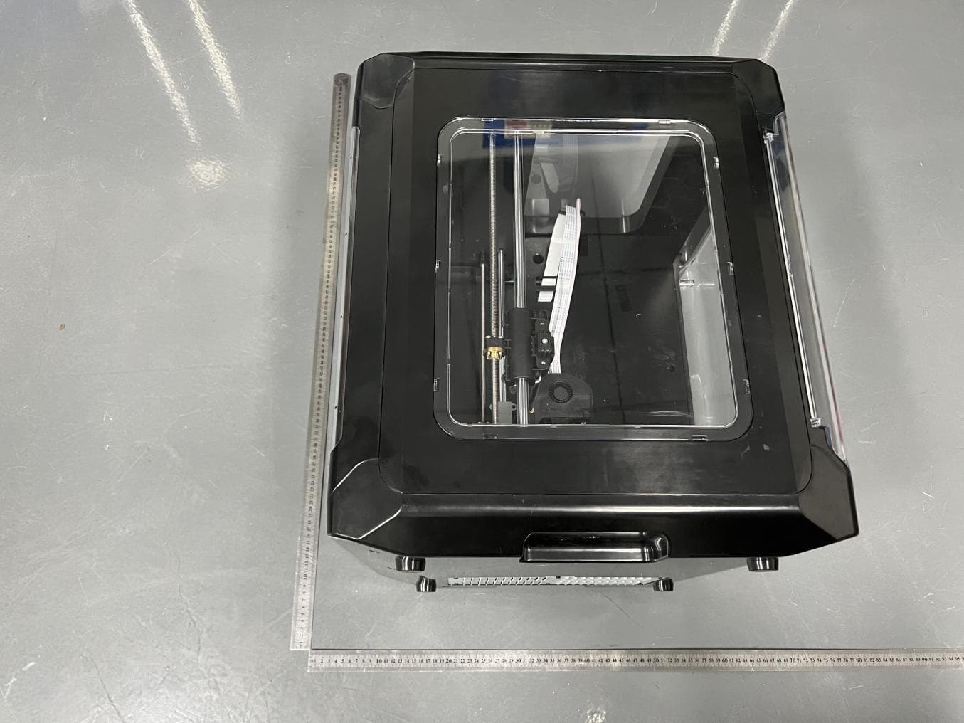
EXHIBIT A - EUT EXTERNAL PHOTOGRAPHS EUT – All View EUT – Top View EUT – Bottom View EUT – Left View EUT – Right View EUT –Front View EUT – Rear View EUT – Detail View
Internal Photos
EXHIBIT B - EUT INTERNAL PHOTOGRAPHS EUT – Cover off View EUT – PCB-1 Top View Antenna EUT – PCB-1 Chip View-1 EUT – PCB-1 Chip View-2 EUT – PCB-1 Chip View-3 EUT – PCB-1 Bottom View EUT – PCB-2 Top View EUT – PCB-2 Bottom View EUT – Power Supply Top View EUT – Power Supply Bottom View
RF Exposure Info
Bay Area Compliance Laboratories Corp. (Kunshan) Report No.: RSHF190923001-00A FCC Part 15.247 Page 13 of 66 FCC §1.1310 & §2.1091 –MAXIMUM PERMISSIBLE EXPOSURE (MPE) Applicable Standard According to subpart §2.1091 and subpart §1.1310, systems operating under the provisions of this section shall be operated in a manner that ensures that the public is not exposed to radio frequency energy level in excess of the Commission’s guidelines. Limits for Maximum Permissible Exposure (MPE) (§1.1310, §2.1091) (B) Limits for General Population/Uncontrolled Exposure Frequency Range (MHz) Electric Field Strength (V/m) Magnetic Field Strength (A/m) Power Density (mW/cm 2 ) Averaging Time (minutes) 0.3-1.34 614 1.63 *(100) 30 1.34-30 824/f 2.19/f *(180/f²) 30 30-300 27.5 0.073 0.2 30 300-1500 / / f/1500 30 1500-100,000 / / 1.0 30 f = frequency in MHz; * = Plane-wave equivalent power density; According to §1.1310 and §2.1091 RF exposure is calculated. Calculated Formulary: Predication of MPE limit at a given distance S = PG/4πR² = power density (in appropriate units, e.g. mW/cm 2 ); P = power input to the antenna (in appropriate units, e.g., mW); G = power gain of the antenna in the direction of interest relative to an isotropic radiator, the power gain factor, is normally numeric gain; R = distance to the center of radiation of the antenna (appropriate units, e.g., cm); Calculated Data: Mode Frequency Range (MHz) Antenna Gain Tune up Conducted Power Evaluation Distance (cm) Power Density (mW/cm 2 ) MPE Limit (mW/cm 2 ) (dBi) (numeric)(dBm)(mW) 802.11b 2412~2462 3.0 2.0 17.0050.1220 0.0199 1.0 802.11g 3.0 2.0 17.0050.1220 0.0199 1.0 802.11 n-HT20 3.0 2.0 16.0039.8120 0.0158 1.0 802.11 n-HT40 2422~2452 3.0 2.0 17.0050.1220 0.0199 1.0 Note: The tune up conducted power was declared by the manufacturer. Conclusion: The device meets MPE at distance 20cm.
Test Report
Note: This test report is prepared for the customer shown above and for the device described herein. It may not be duplicated or used in part without prior written consent from Bay Area Compliance Laboratories Corp. This report is valid only with a valid digital signature. The digital signature may be available only under the Adobe software above version 7.0. FCC PART 15.247 TEST REPORT For MakerBot Industries LLC One MetroTech Center, 21st Fl Brooklyn, New York, 11201 United States FCC ID: 2AUPB-MAKERBOT-S Report Type: Original Report Product Type: 3D PRINTER Test Engineer: Stone Zhang Re port Number: RSHF190923001-00A Re port Date: 2019-10-14 Reviewed B y: Oscar Ye EMC Mana ger Prepared By: Bay Area Compliance Laboratories Corp. (Kunshan) No.248 Chenghu Road, Kunshan, Jiangsu province, China Tel: +86-0512-86175000 Fax: +86-0512-88934268 www.baclcorp.com.cn Bay Area Compliance Laboratories Corp. (Kunshan) Report No.: RSHF190923001-00A FCC Part 15.247 Page 2 of 66 TABLE OF CONTENTS GENERAL INFORMATION ....................................................................................................................................... 4 PRODUCT DESCRIPTION FOR EQUIPMENT UNDER TEST (EUT) ..................................................................................... 4 OBJECTIVE ................................................................................................................................................................... 4 RELATED SUBMITTAL(S)/GRANT(S) ............................................................................................................................. 4 TEST METHODOLOGY .................................................................................................................................................. 4 MEASUREMENT UNCERTAINTY .................................................................................................................................... 5 TEST FACILITY ............................................................................................................................................................. 5 SYSTEM TEST CONFIGURATION .......................................................................................................................... 6 DESCRIPTION OF TEST CONFIGURATION ...................................................................................................................... 6 EQUIPMENT MODIFICATIONS ....................................................................................................................................... 6 EUT EXERCISE SOFTWARE .......................................................................................................................................... 6 SUPPORT EQUIPMENT LIST AND DETAILS .................................................................................................................... 9 EXTERNAL I/O CABLE .................................................................................................................................................. 9 BLOCK DIAGRAM OF TEST SETUP ................................................................................................................................ 9 SUMMARY OF TEST RESULTS ............................................................................................................................. 11 TEST EQUIPMENT LIST ......................................................................................................................................... 12 FCC §1.1310 & §2.1091 –MAXIMUM PERMISSIBLE EXPOSURE (MPE) ....................................................... 13 FCC §15.203 - ANTENNA REQUIREMENT ........................................................................................................... 14 APPLICABLE STANDARD ............................................................................................................................................ 14 ANTENNA CONNECTOR CONSTRUCTION .................................................................................................................... 14 FCC §15.207 (a) - AC LINE CONDUCTED EMISSIONS ...................................................................................... 15 APPLICABLE STANDARD ............................................................................................................................................ 15 EUT SETUP ................................................................................................................................................................ 15 EMI TEST RECEIVER SETUP ....................................................................................................................................... 15 TEST PROCEDURE ...................................................................................................................................................... 15 FACTOR & OVER LIMIT CALCULATION ...................................................................................................................... 16 TEST RESULTS SUMMARY .......................................................................................................................................... 16 TEST DATA ................................................................................................................................................................ 16 FCC §15.209, §15.205 & §15.247(d) - SPURIOUS EMISSIONS ............................................................................. 19 APPLICABLE STANDARD ............................................................................................................................................ 19 EUT SETUP ................................................................................................................................................................ 19 EMI TEST RECEIVER SETUP ...........................................................................…
Text truncated - open the document above for the full version.
Test Setup Photos
EXHIBIT C - TEST SETUP PHOTOGRAPHS Conducted Emissions (Front View) Conducted Emissions (Side View) Radiated Emissions (Below 1GHz) Radiated Emissions (Above 1GHz)
Contact Information
Applicant
Barbara Spampinato(Senior Regulatory Compliance Engineer)
Test Firm
Bay Area Compliance Laboratories Corp. (Kunshan)Mr. John Chan
[email protected]+86 0512 86175000
Technical Specifications
| # | Rule Parts | Frequency Range | Power Output |
|---|---|---|---|
| 1 | 15C | 2.41 GHz - 2.46 GHz | 47.00 mW |
Other Applications from MakerBot Industries LLC
2AUPB-MAKERBOT-SL
Nov 09, 20223D Printer
Equipment Class
DTS - Digital Transmission System