2AUTV-PRO250WWireless Outdoor Sensor for Pro1 Wireless HVAC control system
Pro1 Technologies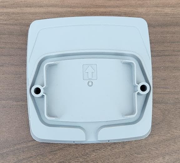
Click to zoom
Application Details
- Equipment Class
- DSS - Part 15 Spread Spectrum Transmitter
- Date of Grant
- Apr 09, 2024
- Application Purpose
- Original Equipment
- Date of Application
- Apr 09, 2024
- Equipment Note
- Wireless Outdoor Sensor for Pro1 Wireless HVAC control system
- Frequency Range
- 902.52000000 - 927.56000000
- Company
- Pro1 Technologies
- Country
- United States
Documents & Files
Document Text
Text extracted from the exhibit documents filed with the FCC. Open a document above to read the original.
Users Manual
R250W Outdoor Sensor and User Guide Pro1 Technologies P.O. Box 3377 Springfield, MO 65804 Toll Free : 888-776-1427 Web: www.pro1iaq.com Hours of Operation: M-F 9AM - 6PM Eastern Table of Contents Specifications Installing Batteries and Mounting Establishing Communication Technician Setup and Warranty Page Una version en espanol de este manual se puede descargar en la pagina web de la compania. Rev. 2339 Installing Batteries and Mounting 2 3 4-7 1 2 Establishing Communication 3 4 To install 2 AA batteries remove the cover of the front housing and insert batteries as show below. Installing Batteries Do not operate the cooling system if the outdoor temperature is below 50 ̊F (10 ̊ C) to prevent possible compressor damage. Caution: Equipment Damage Hazard U.S. Registered Trademark. Patents pending Copyright 2023 All Rights Reserved. The R250W requires the PROsync™ Wireless System T755WHO thermostat. NOTE About Low Batteries: When the outdoor battery needs to be changed the Main Thermostat will flash OUTDOOR LO BAT as seen above. When OUTDOOR LO BAT appears, user has ~3 months to change the batteries. Before putting the inside cover back on, proceed to the next page to establish a connection between the Equipment Module and the Outdoor Sensor. Connecting to the Main Thermostat The Outdoor Sensor must be paired to a PROsync Equipment Module (sold seperately) To check the connection of the outdoor remote sensor to the equipment module at the installation site, press the button on the outdoor sensor and wait 15 seconds. The LED will blink white while the outdoor sensor is checking the connection and then show the following status indicators: BLUE - Good Connection - YELLOW - Weak Connection - RED - No Connection / out of range. Mounting the Outdoor Remote Sensor For best results, install on a north-facing wall, sheltered by a roof overhang or something similar. Do not install in direct sunlight. IMPORTANT: Specifications Operating Temperature ...................... -40 ̊F to 140 ̊F (-40 ̊C to 60 ̊ C) Operating humidity............................... 90% non-condensing maximum Dimensions of sensor .......................... 3.875”W x 3.875”H x 1.125”D Checking outdoor remote sensor temperature: After the outdoor remote sensor is paired, on the indoor remote sensor press the light button and WAIT 30 seconds. The antenna icon will flash 3 times, and the outdoor temperature will appear at the top of the LCD screen. To install remove the front cover and place a screw in the left and right screw holes. FAN ON LEAVE Set At COOL ON Installation Tips 1 Mounting the Outdoor Remote Sensor North Facing Wall Roof Shelter On the Equipment Module: 1. Press the PAIR button below the LED. - The equipment module will begin double blinking pink for 2 minutes while it waits for a remote to join. 2. Press the button on the inside of the outdoor remote sensor. The LED on the outdoor remote sensor will begin to flash pink. 3. When the equipment module receives the pairing message , it will blink blue repeatedly, then return to blinking green. 4. The outdoor remote sensor will blink green 10 times when it is paired, then the LED on the outdoor sensor will turn off. Battery types • Alkaline AA batteries will perform well in most applications. • Lithium AA primary cell batteries are recommended for cold climates. See the battery manufacturer product specifications for details. • Rechargeable batteries are not recommended. Set At Menu Zone LEAVE Menu Zone Technician SetupTechnician Setup 65 Tech Setup StepsAdjustment OptionsDefault LCD Will Show Tech Setup StepsAdjustment OptionsDefault LCD Will Show Technician Setup 87 This device complies with part 15 of the FCC Rules. Operation is subject to the following two conditions: (1) This device may not cause harmful interference, and (2) this device must accept any interference received, including interference that may cause undesired operation. Any changes or modifications not expressly approved by the party responsible for compliance could void the user’s authority to operate this equipment. Note: This equipment has been tested and found to comply with the limits for a Class B digital device, pursuant to part 15 of the FCC Rules. These limits are designed to provide reasonable protection against harmful interference in a residential installation. This equipment generates, uses and can radiate radio frequency energy and, if not installed and used in accordance with the instructions, may cause harmful interference to radio communications. However, there is no guarantee that interference will not occur in a installation. If this equipment does cause harmful interference to radio or television reception, which can be determined by turning the equipment off and on, the user is encouraged to try to correct the interference by one or more of the following measures: · Reorient or relocate the receiving antenna. · Increase the separation between the equipment and receiver. · Connect the equipment into an outlet on a circuit different from that to which the receiver is connected. · Consult the dealer or an experienced radio/TV technician for help. FCC RF Exposure Statement The device shall be used in such a manner that the potential for human contact normal operation is minimized. This equipment complies with FCC radiation exposure limits set forth for an uncontrolled environment. This equipment should be installed and operated with a minimum distance of 20cm between the radiator and your body. This device and its antenna(s) must not be co-located or operating in conjunction with any other antenna or transmitter. These steps must be done from the MAIN Thermostat in your PROsync System. This thermostat has a technician setup menu for easy installer configuration. To set up the thermostat for your particular application: 1. Press the MENU button. 2. Press and hold the technician setup button for 3 seconds. This 3 second delay is designed so that homeowners do not accidentally access the…
Text truncated - open the document above for the full version.
Attestation Statements
3/29/2024 12303 Airport Way Suite 145 Broomfield, CO 80021 TO: Federal Communication Commission Equipment Authorization Division Application Processing Branch 7435 Oakland Mills Rd Columbia, MD 21046 Date Pursuant to FCC 22-84 Report and Order and KDB 986446 D01 Covered Equipment v01, the Commission adopted new FCC requirements to protect the nation’s networks and supply chains from equipment that poses an unacceptable risk to national security or the safety of U.S. persons. Specifically, the Commission adopted rules that prohibit equipment authorization for “covered” telecommunications equipment and video surveillance equipment produced by entities identified on the Commission’s Covered List. Certifications FCC ID: 2AUTV-PRO250W concerning “covered” equipment. Section 2.911(d)(5)(i)-(ii). Pro1 IAQ, LLC (“the applicant”) certifies that the equipment for which authorization is sought is not “covered” equipment prohibited from receiving an equipment authorization pursuant to section 2.903 of the FCC rules. Pro1 IAQ, LLC certifies that as of the date of the filing of the application, the applicant is not identified on the covered list as an entity producing covered equipment. Thank you. Regards, Signature: Date: 3/29/2024 Signed by (printed name): Christopher Bles
Attestation Statements
3/29/2024 12303 Airport Way Suite 145 Broomfield, CO 80021 TO: Federal Communication Commission Equipment Authorization Division Application Processing Branch 7435 Oakland Mills Rd Columbia, MD 21046 Date: 3/29/2024 Pursuant to FCC 22-84 Report and Order and KDB 986446 D01 Covered Equipment v01, the Commission adopted new FCC requirements to protect the nation’s networks and supply chains from equipment that poses an unacceptable risk to national security or the safety of U.S. persons. Specifically, the Commission adopted rules that prohibit equipment authorization for “covered” telecommunications equipment and video surveillance equipment produced by entities identified on the Commission’s Covered List. Certification designating a U.S. agent for service of process. As required by section 2.911(d)(7), the applicant must designate a contact located in the United States for purposes of acting as the applicant’s agent for service of process, regardless of whether the applicant is a domestic or foreign entity. An applicant located in the United States may designate itself as the agent for service of process. 1. Be signed by both the applicant and the designated agent for service of process if the agent is different from the applicant. 2. Pro1 IAQ (“the applicant”) consent to accept the service of process. 3. Pro1 IAQ 12303 Airport Way Suite 145 Broomfield, CO 80021 [email protected] 4. FRN number 0028899185 Pro1 IAQ acknowledges to maintain an agent for no less than one year after the grantee has terminated all marketing and importation or the conclusion of any Commission-related proceeding involving the equipment. If the agent changes then the TCB and the FCC must be notified. Regards, Signature: Date: 3/29/2024 Signed by (printed name): Christopher Bles
External Photos
2AUTV-PRO250W External Photos Front Back
ID Label/Location Info
This device complies with Part 15 of the FCC Rules. Operation is subject to the following two conditions: (1) this device may not cause harmful interference, and (2) this device must accept any interference received, including interference that may cause undesired operation. FCC ID: 2AUTV-PRO250W
ID Label/Location Info
FCC Label location for 2AUTV-PRO250W Interior view of rear product housing FCC Label Location Notes •Label is installed on the interior of the rear product housing •The product requires the rear housing to operate
Internal Photos
2AUTV-PRO250W Internal Photos Open Housing PCB Front PCB Back
RF Exposure Info
1516 Centre Circle, Downers Grove IL 60515 RF EXPOSURE EXHIBIT Manufacturer Name Pro1 AIQ Inc Manufacturer Address 2650 N Westgate Ave Ste 112 Springfield, MO 65803 Model No. Wireless Outdoor Remote Sensor, Model No.: R250W HVIN NA Specifications FCC “Code of Federal Regulations” Title 47 Part 1.1307(b) FCC “Code of Federal Regulations” Title 47 Part 2.1093 Industry Canada RSS-102 Test Facility Elite Electronic Engineering, Inc. 1516 Centre Circle, Downers Grove, IL 60515 FCC Reg. Number: 269750 IC Reg. Number: 2987A CAB Identifier: US0107 Test Procedure FCC KDB 447498 D01 General RF Exposure Guidance v06 RSS-102, Issue 5 Radio Frequency (RF) Exposure Compliance of Radiocommunication Apparatus (All Frequency Bands ANSI/IEEE C95.1-1992, "Safety Levels with Respect to Human Exposure to Radio Frequency Electromagnetic Fields, 3 kHz to 300 GHz," Evaluation Distance 20 cm Table A.1 Radio Acces s Technology ƒ Transmit Frequency (MHz) ERP/P (dBm) ERP/P (mW) ERP/P Exemption Thres hold (mW) Exempt /Not Exempt TRUEFHSS902.5216.140.738027781841 Exempt - (B)
Test Report
Application Note DN616 SWRA345A Page 1 of 20 Test Report for DN024 (CC-Antenna-DK Board #6) By Richard Wallace Table of Contents 1 SINGLE BAND MODE 2 1.1 OTA TEST RESULTS FOR FREQUENCY 868.000 MHZ 2 1.1.1 RP_868.000_tot 3 1.1.2 RP_868.000_hor 4 1.1.3 RP_868.000_ver 5 1.1.4 Radiation Patterns 6 2 DUAL BAND MODE 8 2.1 OTA TEST RESULTS FOR FREQUENCY 868.000 MHZ 8 2.1.1 RP_868.000_tot 9 2.1.2 RP_868.000_hor 10 2.1.3 RP_868.000_ver 11 2.1.4 Radiation Patterns 12 2.2 OTA TEST RESULTS FOR FREQUENCY 2440.000 MHZ 14 2.2.1 RP_2440.000_tot 15 2.2.2 RP_2440.000_hor 16 2.2.3 RP_2440.000_ver 17 2.2.4 Radiation Patterns 18 3 GENERAL INFORMATION 20 3.1 DOCUMENT HISTORY 20 Application Note DN616 SWRA345A Page 2 of 20 1 SINGLE BAND MODE 1.1 OTA Test Results for Frequency 868.000 MHz Total Radiated Power -0.10 dBm Peak EIRP 5.05 dBm Directivity 5.15 dBi Efficiency -0.10 dB Efficiency 97.67 % Gain 5.05 dBi NHPRP 45° -2.77 dBm NHPRP 45° / TRP -2.67 dB NHPRP 45° / TRP 54.13 % NHPRP 30° -4.79 dBm NHPRP 30° / TRP -4.69 dB NHPRP 30° / TRP 33.97 % NHPRP 22.5° -6.05 dBm NHPRP 22.5° / TRP -5.94 dB NHPRP 22.5° / TRP 25.44 % UHRP -3.75 dBm UHRP / TRP -3.65 dB UHRP / TRP 43.18 % LHRP -2.56 dBm LHRP / TRP -2.45 dB LHRP / TRP 56.82 % Front/Back Ratio 3.78 PhiBW 293.4 deg PhiBW Up 212.0 deg PhiBW Down 81.5 deg ThetaBW 75.5 deg ThetaBW Up 34.2 deg ThetaBW Down 41.3 deg Boresight Phi 135 deg Boresight Theta 180 deg Maximum Power 5.05 dBm Minimum Power -11.70 dBm Average Power 1.12 dBm Max/Min Ratio 16.75 dB Max/Avg Ratio 3.93 dB Min/Avg Ratio -12.82 dB Best Single Value 4.24 dBm Best Position Phi = 105 deg; Theta = 165 deg; Pol = Hor Application Note DN616 SWRA345A Page 3 of 20 1.1.1 RP_868.000_tot Azimuth (deg) Elevation 0 deg (dB) Elevation 15 deg (dB) Elevation 30 deg (dB) Elevation 45 deg (dB) Elevation 60 deg (dB) Elevation 75 deg (dB) Elevation 90 deg (dB) Elevation 105 deg (dB) 0.00 0.25 0.39 1.35 3.43 1.73 -5.42 -0.30 -1.15 15.00 0.56 0.37 1.37 3.47 1.19 -5.94 0.04 -0.08 30.00 0.88 0.68 0.82 3.18 -0.07 -6.04 0.26 0.31 45.00 1.34 0.44 0.53 2.36 -1.27 -6.48 -0.26 0.06 60.00 1.64 0.51 -0.41 1.44 -3.46 -6.03 -1.00 -0.73 75.00 2.01 0.10 -1.23 -0.02 -6.07 -5.69 -2.09 -2.04 90.00 2.22 -0.32 -1.66 -1.69 -9.13 -4.52 -2.91 -2.81 105.00 2.57 -0.53 -1.80 -3.33 -10.79 -3.13 -2.78 -2.56 120.00 2.91 0.02 -1.24 -4.45 -7.84 -2.01 -1.96 -0.90 135.00 3.29 0.63 0.12 -3.88 -5.87 -1.02 -1.04 0.54 150.00 3.49 1.65 1.01 -2.51 -3.72 -0.49 -0.70 1.28 165.00 3.89 2.38 2.13 -1.07 -2.39 -0.26 -0.87 1.59 180.00 4.07 3.22 2.77 0.30 -1.54 -0.09 -1.69 1.09 195.00 4.25 4.00 3.31 0.78 -0.98 -0.04 -2.74 0.28 210.00 4.27 4.36 3.39 0.89 -1.69 -0.14 -4.25 -0.91 225.00 4.34 4.47 3.33 0.08 -2.74 -0.60 -5.62 -2.26 240.00 3.84 4.47 3.03 -1.03 -5.09 -1.75 -6.37 -3.44 255.00 3.56 4.06 2.49 -2.53 -7.61 -3.19 -6.38 -4.16 270.00 3.12 3.30 1.85 -4.01 -7.48 -5.46 -5.22 -4.52 285.00 2.47 2.36 1.30 -3.41 -3.95 -7.27 -3.67 -3.85 300.00 1.79 1.53 1.08 -1.45 -1.97 -6.84 -2.34 -4.03 315.00 1.27 0.82 1.11 0.40 0.20 -5.90 -1.32 -3.68 330.00 0.85 0.38 1.24 1.79 1.19 -4.88 -0.82 -3.45 345.00 0.71 0.49 1.59 2.91 1.77 -4.89 -0.65 -2.37 360.00 0.31 0.39 1.62 3.39 1.42 -5.47 -0.34 -1.22 (continuation of the "RP_868.000_tot" table from column 9 ...) Azimuth (deg) Elevation 120 deg (dB) Elevation 135 deg (dB) Elevation 150 deg (dB) Elevation 165 deg (dB) Elevation 180 deg (dB) 0.00 0.51 4.19 3.56 2.37 1.46 15.00 0.49 4.36 3.61 2.41 1.16 30.00 -0.13 3.92 3.47 2.71 1.24 45.00 -1.95 3.16 3.49 3.11 1.75 60.00 -4.81 2.21 3.57 3.74 2.28 75.00 -7.98 1.23 3.66 3.97 3.21 90.00 -8.05 0.50 3.83 4.26 4.05 105.00 -4.18 0.15 4.12 4.59 4.69 120.00 -1.17 0.73 4.26 4.62 4.95 135.00 0.98 1.31 4.32 4.51 5.05 150.00 2.00 1.78 4.00 4.20 4.92 165.00 2.35 1.99 3.59 3.85 4.52 180.00 2.07 1.50 2.93 3.50 3.90 195.00 1.50 0.54 1.83 3.16 3.35 210.00 0.53 -0.82 0.74 3.10 2.84 225.00 -0.39 -3.53 -0.38 2.76 2.85 240.00 -1.43 -7.46 -1.74 2.67 2.84 255.00 -2.14 -11.70 -2.04 2.58 3.14 270.00 -2.22 -8.06 -1.31 2.58 3.28 285.00 -1.99 -3.70 0.05 2.61 3.46 300.00 -1.19 -0.94 1.21 2.44 3.55 315.00 -0.85 1.10 2.42 2.58 3.23 330.00 -0.13 2.52 2.82 2.34 2.92 345.00 0.09 3.54 3.43 2.15 2.11 360.00 0.63 4.01 3.49 2.22 1.70 Application Note DN616 SWRA345A Page 4 of 20 1.1.2 RP_868.000_hor Azimuth (deg) Elevation 0 deg (dB) Elevation 15 deg (dB) Elevation 30 deg (dB) Elevation 45 deg (dB) Elevation 60 deg (dB) Elevation 75 deg (dB) Elevation 90 deg (dB) Elevation 105 deg (dB) 0.0 -9.44 -14.82 -16.34 -8.91 -10.57 -15.91 -16.16 -10.41 15.0 -7.86 -11.19 -11.51 -6.28 -10.46 -12.91 -12.70 -7.31 30.0 -4.05 -6.25 -7.17 -4.41 -11.15 -9.80 -8.60 -5.47 45.0 -1.02 -3.34 -4.52 -3.91 -11.69 -8.25 -6.03 -4.03 60.0 0.60 -1.49 -3.48 -3.48 -13.35 -6.51 -4.53 -3.17 75.0 1.67 -0.80 -2.93 -3.97 -15.27 -5.91 -3.93 -3.14 90.0 1.97 -0.78 -2.76 -4.30 -16.63 -5.40 -3.69 -3.11 105.0 1.74 -1.39 -3.49 -4.88 -17.24 -5.53 -3.85 -3.55 120.0 0.94 -2.49 -4.73 -5.90 -18.51 -6.07 -4.33 -3.46 135.0 -0.37 -4.74 -6.58 -7.53 -21.81 -6.93 -4.84 -4.45 150.0 -2.92 -8.55 -10.02 -9.68 -22.90 -7.93 -6.09 -5.25 165.0 -7.02 -17.21 -13.69 -12.60 -22.90 -10.64 -7.62 -7.07 180.0 -13.09 -11.28 -11.16 -14.66 -22.90 -12.69 -10.98 -9.98 195.0 -9.32 -5.18 -6.19 -11.82 -21.59 -13.01 -15.92 -14.93 210.0 -4.20 -1.73 -3.13 -8.54 -17.29 -10.69 -18.19 -16.23 225.0 -1.37 0.37 -0.66 -5.89 -13.37 -9.26 -12.31 -10.93 240.0 0.53 1.91 0.63 -4.46 -11.88 -8.18 -8.63 -8.06 255.0 1.81 2.50 1.49 -3.77 -10.68 -7.51 -6.89 -6.10 270.0 2.50 2.63 1.60 -4.18 -10.64 -8.19 -6.18 -5.24 285.0 2.38 2.24 1.20 -5.26 -11.09 -9.12 -6.08 -4.73 300.0 1.64 1.39 0.21 -7.20 -13.35 -10.05 -6.56 -6.13 315.0 0.38 -0.35 -1.81 -11.03 -16.87 -11.72 -8.29 -7.76 330.0 -1.59 -2.84 -4.17 -18.07 -18.11 -13.71 -10.26 -11.12 345.0 -4.71 -6.35 -8.73 -14.71 -15.59 -16.67 -15.53 -13.20 360.0 -9.06 -11.00 -15.19 -10.44 -12.30 -16.83 -20.45 -12.78 (continuation of the "RP_868.000_hor" table from column 9 ...) Azimuth (deg) Elevation 120 deg (dB) Elevation 135 deg (dB) Elevation 150 deg (dB) Elevation 165 deg (dB) Elevation 180 deg (…
Text truncated - open the document above for the full version.
Test Report
Engineering Test Report No. 2301385-01 Report Date September 5, 2023 Manufacturer Name Pro1 IAQ Inc Manufacturer Address 2650 N Westgate Ave Ste 112 Springfield, MO 65803 Test Item Name Model No. Wireless Outdoor Remote Sensor, Model No.: R250W Date Received August 31, 2023 Test Dates August 31, 2023, and September 1, 2023 Specifications FCC "Code of Federal Regulations" Title 47 Part 15, Subpart C, Section 15.247 Innovation, Science, and Economic Development Canada, RSS-GEN Innovation, Science, and Economic Development Canada, RSS-247 Test Facility Elite Electronic Engineering, Inc. 1516 Centre Circle, Downers Grove, IL 60515 FCC Reg. Number: 269750 IC Reg. Number: 2987A CAB Identifier: US0107 Signature Tested by Mark E. Longinotti Signature Approved by Raymond J. Klouda, Registered Professional Engineer of Illinois – 44894 PO Number PO-2014 This report is for your exclusive use. Any copying or replication of this report to or for any other person or entity, or use of our name or trademark, is permitted only with our prior written permission. This report sets forth our findings solely with respect to the test samples identified herein. The results set forth in this report are not indicative or representative of the quality or characteristics of the lot from which a test sample was taken or any similar or identical product unless specifically and expressly noted. Our report includes all of the tests requested by you and the results thereof based upon the information that you provided to us. You have 60 days from date of issuance of this report to notify us of any material error or omission caused by our negligence, provided, however, that such notice shall be in writing and shall specifically address the issue you wish to raise. A failure to raise such issue within the prescribed time shall constitute your unqualified acceptance of the completeness of this report, the tests conducted and the correctness of the report contents. This report shall not be reproduced, except in full, without the written approval of Elite Electronic Engineering Inc. Elite Electronic Engineering Incorporated certifies that the information contained in this report was obtained under conditions which meet or exceed those specified in the FCC "Code of Federal Regulations" Title 47 Part 15, Subpart C, Section 15.247 and Innovation, Science, and Economic Development Canada, RSS-247 test specifications. The data presented in this test report pertains to the EUT on the test dates specified. Any electrical or mechanical modifications made to the EUT subsequent to the specified test date will serve to invalidate the data and void this certification. This report must not be used to claim product certification, approval, or endorsement by A2LA, NIST, or any agency of the Federal Government. Engineering Test Report No. 2301385-01 This report shall not be reproduced, except in full, without the written approval of Elite Electronic Engineering Inc. Page 2 of 66 Table of Contents 1. Report Revision History ............................................................................................................................ 3 2. Introduction ............................................................................................................................................... 4 2.1. Scope of Tests .......................................................................................................................................... 4 2.2. Purpose ..................................................................................................................................................... 4 2.3. Identification of the EUT ............................................................................................................................ 4 3. Power Input ............................................................................................................................................... 5 4. Grounding ................................................................................................................................................. 5 5. Support Equipment ................................................................................................................................... 5 6. Interconnect Leads .................................................................................................................................... 5 7. Modifications Made to the EUT ................................................................................................................. 5 8. Modes of Operation ................................................................................................................................... 5 9. Test Specifications .................................................................................................................................... 5 10. Test Plan ................................................................................................................................................... 6 11. Deviation, Additions to, or Exclusions from Test Specifications ............................................................... 6 12. Laboratory Conditions ............................................................................................................................... 6 13. Summary ................................................................................................................................................... 6 14. Sample Calculations ................................................................................................................................. 7 15. Statement of Conformity ........................................................................................................................... 7 16. Certification ............................................................................................................................................... 7 17. Photographs o…
Text truncated - open the document above for the full version.
Test Setup Photos
Engineering Test Report No. 2301385-01 Page 40 of 66 Test Setup for Spurious Radiated Emissions, 30MHz – 1GHz – Antenna Polarization Horizontal Test Setup for Spurious Radiated Emissions, 30MHz – 1GHz – Antenna Polarization Vertical Engineering Test Report No. 2301385-01 Page 41 of 66 Test Setup for Spurious Radiated Emissions, Above 1GHz – Antenna Polarization Horizontal Test Setup for Spurious Radiated Emissions, Above 1GHz – Antenna Polarization Vertical
Contact Information
Applicant
CHRISTOPHER BLES
Technical Contact
Pro1 IAQ, LLCChristopher Bles
[email protected]8887761427
12303 Airport Way · Broomfield · United States
Non-Technical Contact
Pro1 IAQ, LLC
[email protected]8887761427
Test Firm
Elite Electronic Engineering Inc.Kevin Halpin
Technical Specifications
| # | Rule Parts | Frequency Range | Power Output |
|---|---|---|---|
| 1 | 15C | 902.52 MHz - 927.56 MHz | 24.10 mW |