2AUXB-DSBC070Outdoor temperature and humidity sensor
Hangzhou Roombanker Technology Co., Ltd.
Click to zoom
Application Details
- Equipment Class
- DTS - Digital Transmission System
- Date of Grant
- Apr 28, 2021
- Application Purpose
- Original Equipment
- Date of Application
- Apr 28, 2021
- Equipment Note
- Outdoor temperature and humidity sensor
- Frequency Range
- 2405.00000000 - 2475.00000000
- Country
- China
Documents & Files
Document Text
Text extracted from the exhibit documents filed with the FCC. Open a document above to read the original.
Users Manual
User Manual Zigbee Temperature&humidity sensor DSBC-070-2 Product Introduction Directions For Installation Screw fixing type 3M adhesive type Attention Product Overview Power On/Off Product Function DSBC-070-2 is an Indoor temperature and humidity Zigbee sensor, Suitable for outdoor environment temperature and humidity detection. It has excellent function of ultra-low power consumption, a red LED lamp and a button switch (low power setting, pairing setting). Power On :Press button for 5 seconds to start up in the Power off state, the indicator LED will be flash 3 times (f=1Hz). Power Off: Press button for 15 seconds to power off in the Power on state, the indicator LED will be flash 5 times (f=2Hz). Pair 1.In the power on state ,press the button to enter the pairing mode, and it can pair to gateway or mobile phone to config the beacon parameter 2.In this state, the red LED will flash in 1Hz ,and the product can be search and pair. 1.Drill holes 3mm in the corresponding positions of the wall, and plug the expansion screw cap into the hole 2.Place the bracket in the corresponding position and fix it with screws; 1: Select the adhesive tape to stick to the back of the device, and tear off the adhesive tape on the back of the beacon sensor; 2Just stick the beacon sensor to the surface of the object; 1.Being close to a metal object will interfere with the signal, causing the signal to be weaken. 2.Note the distance between DSBC-070-2 and the receiver to guarantee the accuracy of receiving. 3.Keep away from the corrosive objects. 4.When installing, make sure that the sensor part is installed facing down. FCC Warning FCC ID: 2AUXB-DSBC070 This device complies with Part 15 of the FCC Rules. Operation is subject to the following two conditions: (1) this device may not cause harmful interference, and (2) this device must accept any interference received, including interference that may cause undesired operation This device has been tested and found to comply with the limits for a Class B digital device, pursuant to Part 15 of the FCC Rules. These limits are designed to provide reasonable protection against harmful interference in a residential installation. This device generates, uses and can radiate radio frequency energy and, if not installed and used in accordance with the instructions, may cause harmful interference to radio communications. OTA The product support OTA function, that the gateway and device management platform have been bound, sensor terminal device and gateway have been paired successfully. Upload OTA firmware to platform, the platform issues upgrade instructions to the specified sensor terminals, the gateway downloads and verifies OTA firmware and saves it locally. Then sensor terminals send query whether have OTA firmware to the gateway every 6 hours (or power off the sensor terminal and then on, it will sends query whether have OTA firmware to the gateway within 5 minutes ). If the gateway has the relevant OTA firmware, the sensor start the OTA. Low voltage indication When the battery level is lower than 30%, the product will enter the low battery mode, the LED light will flash per 10s, and the gateway can also obtain the product’s battery information from the data packet Product Specification Product Name Model No. Battery Capacity Product Size Protocol Beacon sensor 180mAh 45.5*45.5*13mm Zigbee 3.0 DSBC-070-2 100m 17g 0~100 -4~65°C Temp Humidity Distance Weight 3M 3M 3M 3M 3M 3M Indicator LED However, there is no guarantee that interference will not occur in a particular installation. If this device does cause harmful interference to radio or television reception, which can be determined by turning the device off and on, the user is encouraged to try to correct the interference by one or more of the following measures: --Reorient or relocate the receiving antenna. --Increase the separation between the device and receiver. --Connect the device into an outlet on a circuit different from that to which the receiver is connected. --Consult the dealer or an experienced radio/TV technician for help Changes or modifications not expressly approved by the party responsible for compliance could void the user's authority to operate the equipment backButtonMain body
Cover Letter(s)
April 08, 2021 Federal Communications Commission Authorization & Evaluation Division 7345 Oakland Mills Road Columbia, Maryland 21046 Authority to Act as Agent On our behalf, I appoint Shenzhen Timeway Testing Laboratories/ Zone C, 1st Floor, Zone C, 1st Floor, Block B, Jun Xiang Da Building, Zhongshan Park Road West, Tong Le Village, Nanshan District, Shenzhen, China (Name of Agent company name and address) to act as our agent in the preparation of this application for equipment certification. I certify that submitted documents properly describe the device or system for which equipment certification is sought. I also certify that each unit manufactured, imported or marketed, as defined in the Federal Communications Commission’s regulations will have affixed to it a label identical to that submitted for approval with this application. For instances where our authorized agent signs the application for certification on our behalf, I acknowledge that all responsibility for complying with the terms and conditions for certification, still resides with Hangzhou Roombanker Technology Co., Ltd./ A#801 Wantong center, Hangzhou, Zhejiang, China <Signature>: Name:Su Lin Title: Applicant Company:Hangzhou Roombanker Technology Co., Ltd.
Cover Letter(s)
April 22, 2021 Equipment Autorisation Division Federal Communications Commission 7435 Oakland Mills Road Columbia, MD 21046 FCC ID: 2AUXB-DSBC070 Product Name: Outdoor temperature and humidity sensor Request for Confidentiality Pursuant to Sections 0.457 and 0.459 of the commissions rules, we hereby request that the following documents be held confidential: • Schematics • Block diagram • Operation description These materials contain trade secrets and proprietary information and are not customarily released to the public. The public disclosure of this information might be harmful to the company and provide unjustified benefits to our competitors. <Signature>: Name:Su Lin Title: Applicant Company:Hangzhou Roombanker Technology Co., Ltd.
ID Label/Location Info
45,56 45,5 Model:DSBC-070-2 FCC ID:2AUXB-DSBC070 Install Notes 1. Stick insulated slice on the battery 2. Drill 3mm holes for anchor 3. Affix the bracket with screws Temperature sensor
RF Exposure Info
FCC ID: 2AUXB-DSBC0 70 RF Exposure Applicable Standard According to §1.1307(b)(5), systems operating under the provision s of this secti on shal l be operate d in a manner that ensure that the publi c is not ex po sed to rad io frequency energ y level in ex cess of the Commission’s guideline. This is a Po rtable dev ice . The Section 4.3.1 and Appendix A of KDB447498 D01 V05 was used as the guidance. Calculation Result (Worse case) [(max. power of channel, including tune-up tolerance, mW)/(min. test separation distance, mm)] · [√f(GHz)] =0.394/5 * 1.55= 0.122, this value is less than 3.0 f or 1-g SAR and ≤ 7.5 for 10-g extremity SAR. The SAR measurement is not necessary.
Test Report
Report No.: TW2103304E File reference No.: 2021-04-15 Applicant: Hangzhou Roombanker Technology Co., Ltd. Product: Indoor temperature and humidity sensor Model No.: DSBC-070-2 Trademark: N/A Test Standards: FCC Part 15.247 Test result: It is herewith confirmed and found to comply with the requirements set up by ANSI C63.10, FCC Part 15.247 for the evaluation of electromagnetic compatibility Approved By Jack Chung Manager Dated: April 15, 2021 Results appearing herein relate only to the sample tested The technical reports is issued errors and omissions exempt and is subject to withdrawal at SHENZHEN TIMEWAY TESTING LABORATORIES Zone C, 1st Floor, Block B, Jun Xiang Da Building, Zhongshan Park Road West, Tong Le Village, Nanshan District, Shenzhen, China Tel (755) 83448688, Fax (755) 83442996, E-Mail:[email protected] Report No.: TW2103304E Page 2 of 47 Date: 2021-04-15 The report refers only to the sample tested and does not apply to the bulk. This report is issued in confidence to the client and it will be strictly treated as such by the SHENZHEN TIMEWAY TESTING LABORATORIES. It may not be reproduced rather in its entirety or in part and it may not be used for adverting. The client to whom the report is issued may, however, show or send it . or a certified copy there of prepared by the SHENZHEN TIMEWAY TESTING LABORATORIES. to his customer. Supplier or others persons directly concerned. SHENZHEN TIMEWAY TESTING LABORATORIES. will not, without the consent of the client enter into any discussion of correspondence with any third party concerning the contents of the report. In the event of the improper use of the report. The SHENZHEN TIMEWAY TESTING LABORATORIES. reserves the rights to withdraw it and to adopt any other remedies which may be appropriate. Special Statement The testing quality ability of our laboratory meet with Quality Law of Peoples Republic of China Clause 19. The testing quality system of our laboratory meet with ISO/IEC-17025 requirements, which is approved by CNAL. This approval result is accepted by MRA of APLAC. Our test facility is recognized, certified, or accredited by the following organizations: CNAL-LAB Code: L2292 The EMC Laboratory has been assessed and in compliance with CNAL/AC01:2002 accreditation criteria for testing Laboratories (identical to ISO/IEC 17025:2005 General Requirements) for the Competence of testing Laboratories. FCC-Registration No.: 744189 The EMC Laboratory has been registered and fully described in a report filed with the (FCC) Federal Communications commission. The acceptance letter from the FCC is maintained in our files. Registration No.: 744189. Industry Canada (IC) —Registration No.:5205A The EMC Laboratory has been registered by Certification and Engineering Bureau of Industry Canada for radio equipment testing with Registration No.: 5205A. A2LA (Certification Number:5013.01) The EMC Laboratory has been accredited by the American Association for Laboratory Accreditation (A2LA). Certification Number:5013.01 Report No.: TW2103304E Page 3 of 47 Date: 2021-04-15 The report refers only to the sample tested and does not apply to the bulk. This report is issued in confidence to the client and it will be strictly treated as such by the SHENZHEN TIMEWAY TESTING LABORATORIES. It may not be reproduced rather in its entirety or in part and it may not be used for adverting. The client to whom the report is issued may, however, show or send it . or a certified copy there of prepared by the SHENZHEN TIMEWAY TESTING LABORATORIES. to his customer. Supplier or others persons directly concerned. SHENZHEN TIMEWAY TESTING LABORATORIES. will not, without the consent of the client enter into any discussion of correspondence with any third party concerning the contents of the report. In the event of the improper use of the report. The SHENZHEN TIMEWAY TESTING LABORATORIES. reserves the rights to withdraw it and to adopt any other remedies which may be appropriate. Test Report Conclusion Content 1.0 General Details .. .. .. 4 1.1 Test Lab Details .. . 4 1.2 Applicant Details . . .. 4 1.3 Description of EUT .. .. 4 1.4 Submitted Sample .. .. . .. 5 1.5 Test Duration .. . 5 1.6 Test Uncertainty . . 5 1.7 Test By . 5 2.0 List of Measurement Equipment . 6 3.0 Technical Details 7 3.1 Summary of Test Results . 7 3.2 Test Standards .. 7 4.0 EUT Modification 7 5.0 Power Line Conducted Emission Test . 8 5.1 Schematics of the Test . 8 5.2 Test Method and Test Procedure . 8 5.3 Configuration of the EUT 8 5.4 EUT Operating Condition 9 5.5 Conducted Emission Limit .. 9 5.6 Test Result .. . 9 6.0 Radiated Emission test .. 10 6.1 Test Method and Test Procedure . 10 6.2 Configuration of the EUT 11 6.3 EUT Operation Condition 11 6.4 Radiated Emission Limit . 11 7.0 6dB Bandwidth Measurement Bandwidth .. .. . .. 21 8.0 Maximum Peak Output Power .. .. 26 9.0 Power Spectral Density Measurement . 28 10.0 Out of Band Measurement .. 33 11.0 Antenna Requirement . . 40 12.0 FCC ID Label . .. .. 41 13.0 Photo of Test Setup and EUT View . 42 Report No.: TW2103304E Page 4 of 47 Date: 2021-04-15 The report refers only to the sample tested …
Text truncated - open the document above for the full version.
Test Setup Photos
Radiated Emission Test Setup:
Contact Information
Applicant
Lin Su
Test Firm
Shenzhen Timeway Testing LaboratoriesTerry Tang
[email protected]+86-755-83448688
Technical Specifications
| # | Rule Parts | Frequency Range | Power Output |
|---|---|---|---|
| 1 | 15C | 2.40 GHz - 2.48 GHz | 3.94 mW |
Other Applications from Hangzhou Roombanker Technology Co., Ltd.
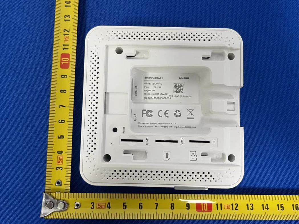
2AUXBDSGW-095
Aug 13, 2024Smart Gateway
Equipment Class
DTS - Digital Transmission System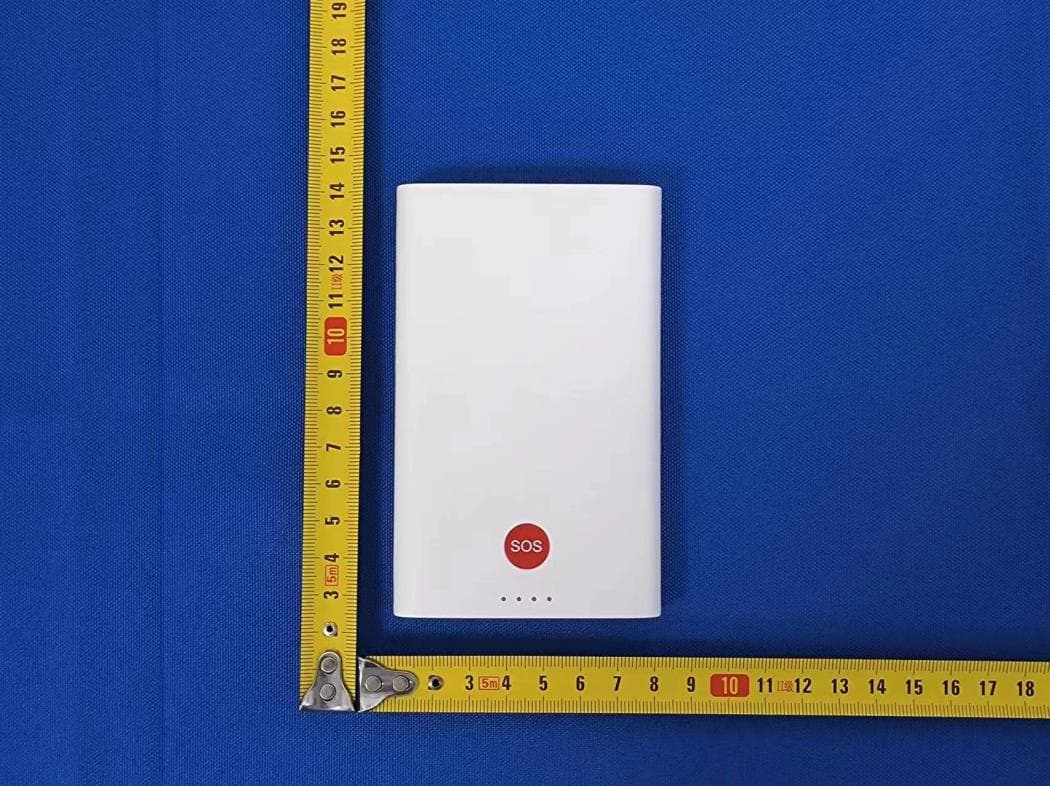
2AUXBDSGW-340
Aug 13, 2024Medical Portable Gateway
Equipment Class
JAB - Part 15 Class B Digital Device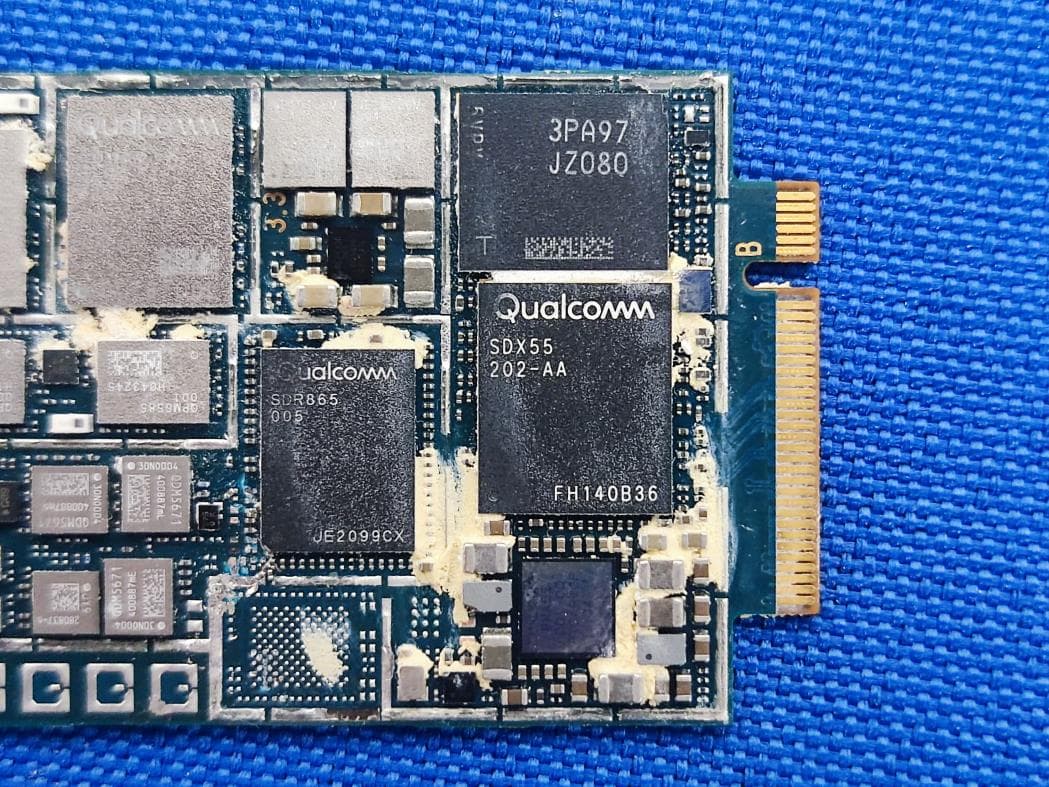
2AUXBDSGW-380
Aug 12, 2024Industrial AI Edge Computing Gateway
Equipment Class
PCB - PCS Licensed Transmitter
2AUXBRBSS-PS1915
Mar 14, 2024PIR Sensor
Equipment Class
JAB - Part 15 Class B Digital Device2AUXBDSBC-230
Jan 30, 2024AOA Tag
Equipment Class
JAB - Part 15 Class B Digital Device