2AV3X-TT001Ultra Wideband (UWB) transceiver IC
TTNG Co.,Ltd.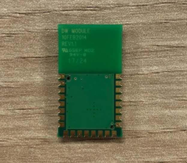
Click to zoom
Application Details
- Equipment Class
- UWB - Ultra Wideband Transmitter
- Date of Grant
- Jun 14, 2020
- Application Purpose
- Original Equipment
- Date of Application
- May 31, 2020
- Equipment Note
- Ultra Wideband (UWB) transceiver IC
- Frequency Range
- 3993.00000000 - 3993.00000000
- Company
- TTNG Co.,Ltd.
- Country
- South Korea
Documents & Files
Document Text
Text extracted from the exhibit documents filed with the FCC. Open a document above to read the original.
Users Manual
1 INSCRIPTION MANUAL INSCRIPTION MANUAL [DWM 1000] The DWM 1000 module is based on Decawave’s DW 1000 Ultra Wideband (UWB) transceiver IC. It integrates antenna, all RF circuitry, power management and clock circuitry in one module. It can be used in 2-way ranging or TDOA location systems to locate assets to a precision of 10cm and supports data rates of up to 6.8 Mbps Key Features IEEE 802.15.4-2011 UWB compliant Supports 4 RF bands from 3.5GHz to 6.5 GHz Programmable transmitter output power Fully coherent receiver for maximum range and accuracy Designed to comply with FCC & ETSI UWB spectral masks Supply voltage 2.8V to 3.6V Low power consumption Data rates of 110 kbps, 850 kbps, 6.8 Mbps Maximum packet length of 1023 bytes for high data throughput applications Integrated MAC support features Supports 2-way ranging and TDOA SPI interface to host processor 23mm x 13mm x 2.9 mm 24pin side castellation package Key Benefits Simplifies integration, no RF design required Very precise location of tagged objects delivers enterprise efficiency gains and cost reductions Extended communications range minimizes required infrastructure in RTLS High multipath fading immunity Supports very high tag densities in RTLS Low cost allows cost-effective implementation of solutions Low power consumption reduces the need to replace batteries and lowers system lifetime costs Applications Precision real time location systems (RTLS) using two-way ranging or TDOA schemes in a variety of markets. Location aware wireless sensor networks (WSNs) 2 INSCRIPTION MANUAL Pin Map Information SIGNAL NAME PIN I/O (Default)DESCRIPTION Digital Interface SPICLK 20 DI SPI clock SPIMISO 19 DO (D-L) SPI data output. SPIMOSI 18 DI SPI data input. SPICSn 17 DI SPI chip select. This is an active low enable input. The high-to-low transition on SPICSn signals the start of a new SPI transaction. WAKEUP 2 DIO When asserted into its active high state the WAKEUP pin brings the DW1000 out of SLEEP or DEPPSLEEP states into operational mode. If unused, this pin can be tied to ground. EXTON 1 DO (O-L) External device enable. Asserted during wake up process and held active until device enters sleep mode. Can be used to control external DC-DC converters or other circuits that are not required when the device is in sleep mode so as to minimize power consumption. IRQ/GPIO8 22 DIO (O-L) Interrupt Request output from the DWM1000 to the host processor. By default IRQ is an active-high output but may be configured to be active low if required. For correct operation in SLEEP and DEPPSLEEP modes it should be configured for active high operation. This pin will float in SLEEP and DEEPSLEEP states and may cause spurious 3 INSCRIPTION MANUAL SIGNAL NAME PIN I/O (Default)DESCRIPTION interrupts unless pulled low. When the IRQ functionality is not being used the pin may be reconfigured as a general purpose I/O line, GPIO8. GPIO7 4 DIO (I) Defaults to operate as a SYNC input. THIS FUNCTIONALITY IS NOT APPLICABLE TO THE DWM1000. This pin may be reconfigured as a general purpose I/O pin, GPIO7 under software control. GPIO6/SPIPHA 9 DIO(I) General purpose I/O pin. On power-up it acts as the SPIPHA (SPI phase selection) pin for configuring the SPI mode of operation. After power-up, the pin will default to a General Purpose I/O pin. GPIO5/SPIPOL 10 DIO (I) General purpose I/O pin. On power-up it acts as the SPIPOL (SPI phase selection) pin for configuring the SPI operation mode. After power- up, the pin will default to a General Purpose I/O pin. GPIO4 11 DIO(I) General purpose I/O pin. GPIO3/TXLED 12 DIO(I) General purpose I/O pin. It may be configured for use as a TXLED driving pin that can be used to light a LED following a transmission. GPIO2/RXLED 13 DIO(I) General purpose I/O pin. It may be configured for use as a RXLED driving pin that can be used to light a LED during receive mode. GPIO1/SFDLED 14 DIO(I) General purpose I/O pin. It may be configured for use as a SFDLED driving pin that can be used to light a LED when SFD (Start Frame Delimiter) is found by the receiver. GPIO0/RXOKLED 15 DIO(I) General purpose I/O pin. It may be configured for use as a RXOKLED driving pin that can be used to light a LED on reception of a good frame. RSTn 3 DIO(O-H) Reset pin. Active Low Output. May be pulled low by external open drain driver to reset the DW1000. Power Supplies VDDAON 5 P External supply for the Always-On (AON) portion of the chip. VDD3V3 6,7 P 3.3V supply pins. Note that for programming the 4 INSCRIPTION MANUAL SIGNAL NAME PIN I/O (Default)DESCRIPTION OTP in the DWM1000 module this voltage may be increased to a nominal value of 3.8 V for short periods. Ground GND 8,16,21, 23,24 G Common ground. Manual Information to the End User: • The OEM integrator has to be aware not to provide information to the end user regarding how to install or remove this RF module in the user’s manual of the end product which integrates this module. The end user manual shall include all required regulatory information/warning as show in this manual. OEM Responsibilities to comply with FCC Regulations The (your product name) Module has been certified for integration into products only by OEM integrators under the following conditions: 1. The antenna(s) must be installed such that a minimum separation distance of 5mm is maintained between the radiator (antenna) and all persons at all times. 2. The transmitter module must not be co-located or operating in conjunction with any other antenna or transmitter. As long as the two conditions above are met, further transmitter testing will not be required. However, the OEM in¬tegrator is still responsible for testing their end-product for any additional compliance requirements required with this module installed (for example, digital device emissions, PC peripheral requirements, etc.). IMPORTANT NOTE: In the event that these conditions cannot be met (for certain configurations or co-location with another transmitter), then the FCC authorization…
Text truncated - open the document above for the full version.
Cover Letter(s)
75, Nowon‐ro, Buk‐gu, Daegu, South Korea Tel/Fax: 82‐70‐8721‐7700 / 82‐53‐715‐1780 Pre-Approval Guidance SUBJECT: PAG Request for FCC ID: 2AV3X-TT001 As per KDB 388624 D02 Pre-Approval Guidance List v16r06, Section II C 2 k, Pre-Approval Guidance, by the FCC, is required for ultra-wideband devices operating under Part 15 Subpart F. We hereby give TIMCO ENGINEERING, INC. permission to file the PAG with the FCC. Sincerely, Date: 2020. 04. 27. ____________________________ Yuseong Kwak Researcher
Cover Letter(s)
Head office & Test Lab: 28(175-20,Annyeong-dong) 406-gil sejaro, Hwaseong-si Gyeonggi-do, Korea Tel: +82-31-222-4251 / Fax: +82-31-222-4252 TIMCO ENGINEERING INC. TCB & FCB 849 NW State Road 45 FCC Approvals Newberry, Florida 32669 Industry Canada Approvals http://www.timcoengr.com Notified Body for Europe 888.472.2424 F 352.472.2030 email: [email protected] 2020. 04. 27. SUBJECT: UPLOAD FILES TO WEBSITE Product: Ultra Wideband (UWB) transceiver IC Applicant: TTNG CO.,Ltd. Model: DWM1000 module Address: 75, Nowon-ro, Buk-gu, Daegu, South Korea FCC ID: 2AV3X-TT001 Dear Sir/Madam As appointed agent for TTNG CO.,Ltd., we submit the application to Timco Engineering Inc, for certification of the above product. Please review all files uploaded to Timco web site. If you have any queries, please do not hesitate to contact us Best regards, Kwang-Yeol Choo / Test Engineer e-mail: [email protected]
Cover Letter(s)
75, Nowon‐ro, Buk‐gu, Daegu, South Korea Tel/Fax: 82‐70‐8721‐7700 / 82‐53‐715‐1780 Federal Communications Commission Authorization and Evaluation Division 1435 Oakland Mills Road Columbia, MD 21046 SUBJECT: FCC Application for FCC ID: 2AV3X-TT001 To Whom It May Concern: We, the undersigned, hereby authorize Kwang-Yeol, Choo at Kostec Co., Ltd on our behalf, to apply to the Federal Communications Commission on our equipment. Any and all acts carried out by Kwang-Yeol, Choo at Kostec Co.,Ltd on our behalf shall have the same effect as acts of our own. Sincerely, Date: 2020. 04. 27. ____________________________ Yuseong Kwak Researcher
Cover Letter(s)
75, Nowon‐ro, Buk‐gu, Daegu, South Korea Tel/Fax: 82‐70‐8721‐7700 / 82‐53‐715‐1780 Office of Engineering and Technology Laboratory Division Equipment Authorization Branch Federal Communications Commission Laboratory 7435 Oakland Mills Road Columbia, MD 21046 Confidentiality Request regarding application for certification of FCC ID: 2AV3X-TT001 Pursuant to Sections 0.457 and 0.459 of the Commission’s Rules, we hereby request confidential treatment of information accompanying this application as outlined below: Exhibit Type File name Block diagram Circuit Description Operational Description Part list Antenna Specification CONF APPENDIX_DWM1000 module_BLK CONF APPENDIX_DWM1000 module_SCH CONF APPENDIX_DWM1000 module_Operational Description CONF APPENDIX_DWM1000 module_BOM CONF APPENDIX_DWM1000 module_Antenna-spec The above materials contain trade secrets and proprietary information not customarily released to the public. The public disclosure of these materials may be harmful to the applicant and provide unjustified benefits to its competitors. The applicant understands that pursuant to Section 0.457 and 0.459 of the Rules, disclosure of this application and all accompanying documentation will not be made before the date of the Grant for this application. Sincerely, Date: 2020. 04. 27. ____________________________ Yuseong Kwak Researcher
Cover Letter(s)
75, Nowon‐ro, Buk‐gu, Daegu, South Korea Tel/Fax: 82‐70‐8721‐7700 / 82‐53‐715‐1780 Federal Communications Commission Authorization and Evaluation Division 1435 Oakland Mills Road Columbia, MD 21046 SUBJECT: Modular Approval Letter for FCC ID: 2AV3X-TT001 Date: 2020. 04. 28. The Device, FCC ID: 2AV3X-TT001 is seeking FCC authorization as a modular transmitter. The EUT meets the requirement for modular approval as detailed in FCC section 15.212. Compliance to each of the requirements is described below: Modular approval requirements Yes No The modular transmitter must have its own RF shielding The radio portion of the motion sensor module has its own RF shielding. The shielding cover is installed at the factory. The modular transmitter must have buffered modulation/data inputs. Please see schematics of the module. The modular transmitter must have its own power supply regulator. The EUT has its own voltage regulation circuitry. Please see schematics of the module. The module must contain a permanently attached antenna, or contain a unique antenna connector, and be marketed and operated only with specific antenna(s), per §§ 15.203, 15.204(b), 15.204(c), 15.212(a), 2.929(b); The EUT meets the FCC antenna requirements. The module must demonstrate compliance in a stand-alone configuration; The EUT was tested in a stand-alone configuration. The module must be labeled with its permanently affixed FCC ID label, or use an electronic display (see KDB Publication 784748); The EUT is labeled with its own FCC ID number The module must comply with all specific rules applicable to the transmitter, including all the conditions provided in the integration instructions by the grantee; The EUT is complaint with all applicable FCC rules. The module must comply with RF exposure requirements The EUT fully complies with RF exposure requirements. Sincerely, Yuseong Kwak
External Photos
Head office & Test Lab: 28(175-20,Annyeong-dong) 406-gil sejaro, Hwaseong-si Gyeonggi-do, Korea Tel: +82-31-222-4251 / Fax: +82-31-222-4252 Page: 1 / 1 Appendix 2. Photographs of EUT [External View] [Front] [Rear]
ID Label/Location Info
Head office & Test Lab: 28(175-20,Annyeong-dong) 406-gil sejaro, Hwaseong-si Gyeonggi-do, Korea Tel: +82-31-222-4251 / Fax: +82-31-222-4252 Page: 1 / 1 Appendix 4. Sample Label & Location Label Information The following is a sample copy of the label that will be placed on back side of the product. The FCC ID is marked in the product label and below information is visible printed on the label. Label location The label shown above shall be permanently affixed at a conspicuous location on the device and be readily visible to the user at the time purchase. The label is located here.
Internal Photos
Head office & Test Lab: 28(175-20,Annyeong-dong) 406-gil sejaro, Hwaseong-si Gyeonggi-do, Korea Tel: +82-31-222-4251 / Fax: +82-31-222-4252 Page: 1 / 2 Appendix 3. Photographs of EUT [Internal View] [ Inside View ] UWB Chip Antenna Head office & Test Lab: 28(175-20,Annyeong-dong) 406-gil sejaro, Hwaseong-si Gyeonggi-do, Korea Tel: +82-31-222-4251 / Fax: +82-31-222-4252 Page: 2 / 2 [Main board(Top)]
RF Exposure Info
MPE Calculation / RF Exposure Product: Ultra Wideband (UWB) transceiver IC Applicant: TTNG CO.,Ltd. Model: DWM1000 module Address: 75, Nowon-ro, Buk-gu, Daegu, South Korea FCC ID: 2AV3X-TT001 Per KDB 447498 D01 General RF Exposure Guidance v06 (10/23/2015) section 4.3.1 (a) Stand alone SAR test exclusion threshold is applied; a) For 100 MHz to 6 GHz and test separation distances ≤ 50 mm, the 1-g and 10-g SAR test exclusion thresholds are determined by the following: [(max. power of channel, including tune-up tolerance, mW) / (min. test separation distance, mm)] ꞏ [√f(GHz)] ≤ 3.0 for 1-g SAR, and ≤ 7.5 for 10-g extremity SAR, where f(GHz) is the RF channel transmit frequency in GHz Power and distance are rounded to the nearest mW and mm before calculation The result is rounded to one decimal place for comparison The values 3.0 and 7.5 are referred to as numeric thresholds in step b) below Freq: 3993 MHz Averaged radiated power [dBm e.i.r.p] = -35.30 Averaged radiated power [mW e.i.r.p] = 0.0003 Min. Test separation distance : 5 mm SAR exclusion threshold: [0.0003/5] x [√3.993] = 0.00012 Therefore, the EUT was not evaluated as the value of SAR exclusion threshold was less than 3 per KDB 447498 D01 v06 section 4.3.1(a)
Test Report
Report No.: KST-FCR-200009(1) KST-FCR-RFS-Rev.0.5 Page: 2 / 28 This report shall not be reproduced except in full without the written approval of KOSTEC Co., Ltd, Table of Contents 1. GENERAL INFORMATION .............................................................................................................. 3 1.1 Test Facility ............................................................................................................................................... 3 1.2 Location .................................................................................................................................................... 3 1.3 Revision History of test report .................................................................................................................. 4 2. EQUIPMENT DESCRIPTION ........................................................................................................... 5 3. SYSTEM CONFIGURATION FOR TEST ......................................................................................... 6 3.1 Characteristics of equipment .................................................................................................................... 6 3.2 Used peripherals list ................................................................................................................................. 6 3.3 Product Modification ................................................................................................................................. 6 3.4 Operating Mode ........................................................................................................................................ 6 3.5 Test Setup of EUT .................................................................................................................................... 6 3.6 Used Test Equipment List ......................................................................................................................... 7 4. SUMMARY TEST RESULTS ............................................................................................................ 9 5. MEASUREMENT RESULTS .......................................................................................................... 10 5.1 Transmission time .................................................................................................................................. 10 5.2 UWB Bandwidth Measurement .............................................................................................................. 12 5.3 Spurious RF Radiated emissions ........................................................................................................... 14 5.4 Radiated Emissions in GPS Bands Measurement ................................................................................. 20 5.5 Peak Emissions within a 50 MHz Bandwidth Measurement .................................................................. 23 5.6 Antenna requirement .............................................................................................................................. 25 5.7 AC Power Conducted emissions ............................................................................................................ 26 Report No.: KST-FCR-200009(1) KST-FCR-RFS-Rev.0.5 Page: 3 / 28 This report shall not be reproduced except in full without the written approval of KOSTEC Co., Ltd, 1. GENERAL INFORMATION 1.1 Test Facility Test laboratory and address KOSTEC Co., Ltd. 28(175-20,Annyeong-dong)406-gil sejaro, Hwaseong-si Gyeonggi-do, Korea Telephone Number: 82-31-222-4251 Facsimile Number: 82-31-222-4252 Registration information KOLAS No.: KT232 RRA (National Radio Research Agency): KR0041 FCC Designation No.: KR0041 IC Designation No.: KR0041 VCCI Membership No.: 2005 1.2 Location KOSTEC Co., Ltd. Report No.: KST-FCR-200009(1) KST-FCR-RFS-Rev.0.5 Page: 4 / 28 This report shall not be reproduced except in full without the written approval of KOSTEC Co., Ltd, 1.3 Revision History of test report Rev. Revisions Effect page Reviewed Date - Initial issue All Gyeong Hyeon, Park 2020. 04. 09. 1 Added AC Conducted Emissions 26 ~ 28 Gyeong Hyeon, Park 2020. 05. 07. Report No.: KST-FCR-200009(1) KST-FCR-RFS-Rev.0.5 Page: 5 / 28 This report shall not be reproduced except in full without the written approval of KOSTEC Co., Ltd, 2. EQUIPMENT DESCRIPTION The product specification described herein was declared by manufacturer. And refer to user’s manual for the details. Equipment Name Ultra Wideband (UWB) transceiver IC Model No DWM1000 module Family model name DWM1000 module (UWB) Usage Ultra Wideband (UWB) transceiver IC Use Environment Hand held Serial Number Proto type Modulation type BPSK/BPM Emission Type IEEE 802.15.4-2011 UWB Maximum Output Power 71.69 dBμV/m Operated Frequency 3 993 MHz Channel Number 1 Operation temperature -10 °C ~ 55 °C Power Source DC 5 V Antenna Description Internal Chip antenna, max gain : 2.73 dBi Remark 1. The device was operating at its maximum output power for all measurements. 2. The radiation measurements are performed in X, Y, Z axis positioning. Only the worst case (Y) is shown in the report. 3. The above DUT’s information was declared by manufacturer. Please refer to the specifications or user manual for more detailed description. FCC ID 2AV3X-TT001 Report No.: KST-FCR-200009(1) KST-FCR-RFS-Rev.0.5 Page: 6 / 28 This report shall not be reproduced except in full without the written approval of KOSTEC Co., Ltd, 3. SYSTEM CONFIGURATION FOR TEST 3.1 Characteristics of equipment Ultra Wideband (UWB) transceiver IC 3.2 Used peripherals list Description Model No. Serial No. Manufacture Remark UWB Receiver None None Decawave - AC/DC Adapter EP-TA12KWK RT1G7CS/B-E RF Tech Bac Ninh Co., Ltd. For AC Conducted Test 3.3 Product Modification N/A 3.4 Operating Mode The EUT was used for making continuous transmitting and receiving mode during the test. 3.5 Test Setup of EUT The measurements were t…
Text truncated - open the document above for the full version.
Test Setup Photos
Head office & Test Lab: 28(175-20,Annyeong-dong) 406-gil sejaro, Hwaseong-si Gyeonggi-do, Korea Tel: +82-31-222-4251 / Fax: +82-31-222-4252 Page: 1 / 2 Appendix 1. Photographs of test setup Radiated RF measurement (Below 1GHz) Radiated RF measurement(Above 1 GHz) Head office & Test Lab: 28(175-20,Annyeong-dong) 406-gil sejaro, Hwaseong-si Gyeonggi-do, Korea Tel: +82-31-222-4251 / Fax: +82-31-222-4252 Page: 2 / 2 AC Conducted measurement(Front) AC Conducted measurement(Rear)
Contact Information
Applicant
Yuseong Kwak
Test Firm
KOSTEC Co., LtdLee Chang-Ho
Technical Specifications
| # | Rule Parts | Frequency Range | Power Output |
|---|---|---|---|
| 1 | 15F | 3.99 GHz - 3.99 GHz | - |