2AV57GP9LTEGO9 Telematics device with on-board Wi-Fi hotspot functionality.
Geotab Inc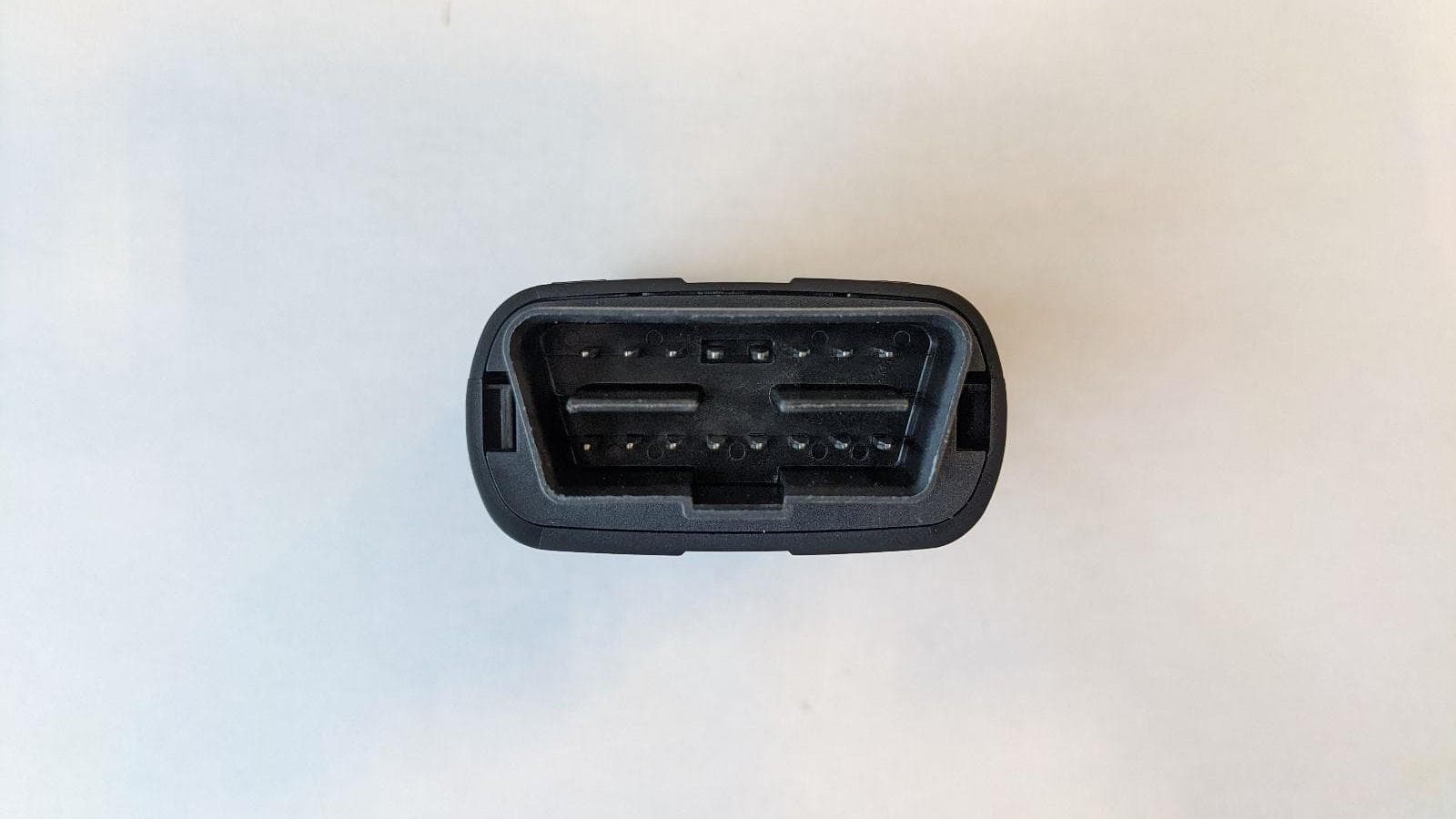
Click to zoom
Application Details
- Equipment Class
- PCB - PCS Licensed Transmitter
- Date of Grant
- Jun 10, 2020
- Application Purpose
- Original Equipment
- Date of Application
- Jun 05, 2020
- Equipment Note
- GO9 Telematics device with on-board Wi-Fi hotspot functionality.
- Frequency Range
- 699.70000000 - 715.30000000
- Company
- Geotab Inc
- Country
- Canada
Documents & Files
Document Text
Text extracted from the exhibit documents filed with the FCC. Open a document above to read the original.
Users Manual
Copyright © Geotab Inc. 2020 - All Rights Reserved | www.geotab.com | Rev 0.5 - 05/2020 ® denotes a trademark of Geotab Inc., registered in Canada, the United States and other countries 1 Geotab ® GO9+ TM — Expandable Telematics Device with Wi- Fi Hotspot For the most up-to-date version, please visit: gtb.page.link/8C7f Security Geotab platform security is designed for end-to-end protection of your data. Key implementations include: ● GO device and network interfaces use authentication, encryption, and message integrity verification; ● GO devices are individualized. Each device uses a unique ID and non-static security key — making it difficult to fake a device’s identity; ● Over-the-air updates use digitally-signed firmware to verify that updates come from a trusted source; ● Geotab uses independent third-party experts to validate the platform from end-to-end; and ● FIPS 140-2 validated by NIST (certificate #3371). Top Features ● Wi-Fi hotspot functionality ● Easy installation ● LTE Connectivity ● Small form factor device ● Intelligent in-vehicle driver coaching ● Breakthrough collision detection and notification ● External device expandability via IOX Technology ● Built-in auto-calibrating accelerometer and gyrometer ● Near-real-time vehicle data ● Fast GPS acquisition time using Almanac OTA support ● Support for GPS+GLONASS connectivity ● Additional native support for more vehicle protocols ● End-to-end cybersecurity GO9+ Device Geotab’s GO9+ telematics device builds on the class-leading GO9 with the added benefit of an on-board Wi-Fi hotspot. Similar to the GO9 ® , the GO9+ offers state-of-the-art GPS technology, g-force monitoring, GEOTAB IOX ® expandability, engine and battery health assessments, and communication on the LTE network. In-vehicle Wi-Fi Hotspot Geotab’s GO9+ telematics device delivers an in-vehicle Wi-Fi hotspot to connect tablets, phones, and other Wi-Fi capable devices. Stay connected to your drivers at all times and improve your fleet functions. Vehicle Tracking Using Geotab’s patented tracking algorithm, the GO9+ accurately recreates vehicle trips and analyzes incidents. Improve fleet safety and performance. The GO9+ relays in- vehicle alerts to notify drivers of infractions in real-time and delivers live driver coaching — with hardware Add-Ons — for improved on-road performance. The GO9+ does not require a Copyright © Geotab Inc. 2020 - All Rights Reserved | www.geotab.com | Rev 0.5 - 05/2020 ® denotes a trademark of Geotab Inc., registered in Canada, the United States and other countries 2 dash-mounted antenna or any wire splicing. Technical Specifications and Features Interfaces Engine Management Legacy Interfaces Physical Interfaces: J1850 PWM, J1850 VPW, J1708, 9141-2 and ISO 14230 (KWP2000) at Pins 2 and 10 Speed: 10.4/41.6 kbaud for J1850, 9141-2 and ISO 14230 and 9600/62500 bps for J1708 Data packet protocols: J1850 PWM, J1850 VPW, J1708, J1708 CAT, ISO Toyota, ISO Vario, ISO Ford, ISO Isuzu Diagnostic/application protocols: OBD2 Standard CAN Physical Interfaces: CAN at Pins 6 and 14, Pins 3 and 11, Pins 2 and 10 Speed: 125/250/500 kbps Data packet protocols: ISO 15765 CAN, GMLAN, VW TP 2.0, SAE J1939-21, SAE J1939-FMS Diagnostic/application protocols: Std OBD2, WWH-OBD, UDS (ISO 14229) Single Wire CAN Physical Interfaces: Single Wire CAN atPin 1 Speed: 33/50/83.3 kbps Data packet protocols: GMLAN, OEM Specific Medium/Low Speed CAN Physical Interfaces: J1939-13 Type 2, TTL CAN at Pins 3 and 11, Pins 2 and 10 Speed: 50/125/250 kbps Data packet protocols: GMLAN,, OEM Specific, ISO 15765 CAN, SAE J1939-21, SAE J1939-FMS Diagnostic/application protocols: Std OBD2, WWH-OBD, UDS (ISO 14229) * 2- or 3-wire install support (for older vehicles/asset tracking) Input/Output Buzzer LEDs — Ignition, GPS, Cellular IOX (more details below) Internal GPS/Cellular antennas Cellular Availability varying on certification — full list of supported countries here. GO9+ LTE ATT LTE (CAT-4): Bands 2/4/5/12 3GPP Compliant GPS Receiver 72-channel engine (GPS/GLONASS/Beidou/Galileo/SBAS/WAAS/EGNOS/MSAS/GAGAN) Copyright © Geotab Inc. 2020 - All Rights Reserved | www.geotab.com | Rev 0.5 - 05/2020 ® denotes a trademark of Geotab Inc., registered in Canada, the United States and other countries 3 Under 1 second Time-To-First Fix for hot and aided starts Cold start: 26s Concurrent GPS & GLONASS system A-GNSS Accuracy: ~2.0 m CEP OTA FW updates supported Onboard Wi-Fi Supports multiple simultaneous connections - 802.11 b/g/n 2.4GHz - DL range: 5 -25 Mbps - UL range: 5 - 10 Mbps Environmental and EMC TBD Copyright © Geotab Inc. 2020 - All Rights Reserved | www.geotab.com | Rev 0.5 - 05/2020 ® denotes a trademark of Geotab Inc., registered in Canada, the United States and other countries 4 Accelerometer & Gyroscope 3D accelerometer and 3D gyroscope. Full-scale acceleration range of ±8g and an angular rate range of ±250 dps. Acceleration and angular rate output data rate of 1.66 kHz. Mechanical Weight: 97 g (0.21 lbs) Dimensions: 77.3 mm L × 53 mm W × 27.5 mm H Housing:PC + ABS - SABIC CY6414 (Flame retardant) Electrical Voltage 12 V and 24 V systems supported Tracking mode (ignition on) WiFi off Peak power: 320 mA @ 12V or 3.84W 184 mA @ 24V or 4.416W Average power: 96.2 mA @ 12V or 1.15W 55.1 mA @ 24V or 1.322 W WiFi on Peak power: 433 mA @ 12V, or 5.196W (Tx power is 23 dBm) 249 mA @ 24V, or 5.975W Average power: 330 mA @ 12V or 3.96W (Tx power is 10dBm) 189.7 mA @ 24V or 4.554 W IOX Operating Mode Up to 2 A Current Resettable overcurrent protection to IOX Compliance Standards: FCC, IC, PTCRB Copyright © Geotab Inc. 2020 - All Rights Reserved | www.geotab.com | Rev 0.5 - 05/2020 ® denotes a trademark of Geotab Inc., registered in Canada, the United States and other countries 5 Carriers: AT&T Over-the-Air (OTA) Support Firmware Updates: For maintenance, new features, and custom applications Parameters: For turning additional features on/off Almanac/Ephemeris Data: For quicker GPS latch In-c…
Text truncated - open the document above for the full version.
Cover Letter(s)
Subject: Validity of Test Results from Testing / Certification of the Integrated Module To Whom It May Concern: We, Geotab Inc, 2440 Winston Park Drive, Oakville Ontario L6H7V2 Canada, due hereby declare that that the test results from conducted tests applied to the radio module: Manufacturer: WNC Model: M18Q2F-1 FCC ID: NKRM18Q2 IC: 4441A-M18Q2 which is incorporated in our host equipment: Manufacturer: Geotab Inc Model: GP9-LTE FCC ID: 2AV57GP9LTE IC: 11140A-GP9LTE and as reported in module test report(s): Report Number: FG622601A, Issue Date: 05/04/2016(UMTS) Report Number: FG622601B, Issue Date: 05/04/2016 (LTE) accurately represent the test results under the new conditions when the identified radio module is integrated in the identified host equipment. By integration of the said radio module into the identified host equipment no changes were made to it or by external adaptation circuitry that impacts the validity of the results of the original module’s test reports; hence conducted signal measurements in the above listed reports also apply to GP9-LTE. Sincerely, Name Title Signature DocuSign Envelope ID: 44309D8A-75E8-4EBC-956C-93BD732A433C AVP, Product Operations Moussa Kfouri
Cover Letter(s)
Letter of Authorization and Anti- Drug Statement Applicant Name: Geotab Inc. Address: 2440 Winston Park Drive, Oakville Ontario, L6H7V2 Canada Product Name: GP9-LTE Model Number: GP9-LTE FCC ID: 2AV57GP9LTE We authorize: CETECOM Inc., to act on our behalf on all matters concerning the above named equipment. We declare that CETECOM Inc. is allowed to forward all information related to the approval project to the Federal Communications Commission and discuss any issues concerning the approval application. The applicant must certify that neither the applicant nor any party to the application is subject to a denial of Federal benefits, that include FCC benefits, pursuant to Section 5301 of the Anti-Drug Abuse Act of 1988, 21 U.S.C. § 862 because of a conviction for possession or distribution of a controlled substance. See 47 CFR 1.2002(b) for the definition of a "party" for these purposes. Does the applicant or authorized agent so certify? ☒ Yes I certify that I am authorized to sign this application. All of the statements herein and the exhibits attached hereto, are true and correct to the best of my knowledge and belief. In accepting a Grant of Equipment Authorization as a result of the representations made in this application, the applicant is responsible for (1) labeling the equipment with the exact FCC ID specified in this application, (2) compliance statement labeling pursuant to the applicable rules, and (3) compliance of the equipment with the applicable technical rules. If the applicant is not the actual manufacturer of the equipment, appropriate arrangements have been made with the manufacturer to ensure that production units of this equipment will continue to comply with the FCC's technical requirements. Authorizing an agent to sign this application, is done solely at the applicant's discretion; however, the applicant remains responsible for all statements in this application. If an agent has signed this application on behalf of the applicant, a written letter of authorization which includes information to enable the agent to respond to the above section 5301 (Anti-Drug Abuse) Certification statement has been provided by the applicant. It is understood that the letter of authorization must be submitted to the FCC upon request, and that the FCC reserves the right to contact the applicant directly at any time. Signature of Authorized Person Filing: Title: Date: DocuSign Envelope ID: 64344655-8E82-4332-9FF0-A24A0F634B44 AVP, Product Operations 5/8/2020
Cover Letter(s)
Federal Communications Commission Equipment Authorization Division 7435 Oakland Mills Road Columbia, MD 21048 Date: Subject: Request for Short Term Confidentiality FCC-ID: 2AV57GP9LTE To Whom It May Concern: In accordance with §0.457(d) and §0.459 of CFR 47, Geotab Inc hereby requests short term confidentiality for documents filed under the following exhibit types: 1. External Photographs 2. Internal Photographs 3. User / Instruction Manual 4. Test Set-up Photographs until the product will be publicly announced. Short term confidentiality release date / period: 180 days from the grant date These items contain detailed system and equipment description and related information about the product which Geotab Inc considers to be proprietary, confidential and a custom design which otherwise would not be released to the general public. Since this design is a basis from which future technological products will evolve, Geotab Inc also feels that this information would be of benefit to its competitors, and that the disclosure of the information in these exhibits would give our competitors an unfair advantage in the market. We are informed and aware of our obligation that we have to inform the involved Telecommunication Certification Body in written and in due time if we intend to market the product prior to the above specified confidentiality release date so that the short term confidentiality classification can be reset prior to product launch. We are aware that exhibit types cover letters, attestations, label document, test reports, RF exposure information (SAR and MPE reports), cannot be requested to be classified confidential and are thus subject to publication, as will be documents of all other exhibits types for which we have not requested a confidentiality classification. Best Regards, ____________________________________ Signature Name: Title: Company Name: Geotab Inc. Address: 2440 Winston Park Drive, Oakville Ontario, L6H7V2 Canada DocuSign Envelope ID: 64344655-8E82-4332-9FF0-A24A0F634B44 AVP, Product Operations Moussa Kfouri 5/8/2020
Cover Letter(s)
Federal Communications Commission Equipment Authorization Division 7435 Oakland Mills Road Columbia, MD 21048 Date: Subject: Request for Permanent Confidentiality FCC ID: 2AV57GP9LTE To Whom It May Concern: In accordance with §0.457(d) and §0.459 of CFR 47, and KDB 726920, Geotab Inc requests permanent confidentiality for documents filed under the following exhibit types: 1. Block Diagram 2. Schematic Diagram 3. Part List 4. Operational Description These items contain detailed system and equipment description and related information about the product which Geotab Inc considers to be proprietary, confidential and a custom design which otherwise would not be released to the general public. Since this design is a basis from which future technological products will evolve, Geotab Inc also feels that this information would be of benefit to its competitors, and that the disclosure of the information in these exhibits would give our competitors an unfair advantage in the market. We are aware that exhibit types cover letters, attestations, label document, test reports, RF exposure information (SAR and MPE reports), cannot be requested to be classified confidential and are thus subject to publication, as will be documents of all other exhibits types for which we have not requested a confidentiality classification. Best Regards, _______________________________ Signature Name: Title: Company Name: Geotab Inc. Address: 2440 Winston Park Drive, Oakville Ontario, L6H7V2 Canada DocuSign Envelope ID: 64344655-8E82-4332-9FF0-A24A0F634B44 Moussa Kfouri 5/8/2020 AVP, Product Operations
External Photos
Top View Bottom View Front View Back View Side View Side View
Internal Photos
Top View (Internal) Primary and Secondary Cellular Antenna 2.4GHz WiFi Antenna Bottom View (Internal) GPS Antenna Mainboard (left) and Daughter board (right) Mainboard with shielding removed Daughter board with shielding removed. WiFi Chip Primary and Secondary Conducted Ports WiFi Antenna PCB Contact Points
Operational Description
GO9+ Operational Description Project code name: PhoenixPlus June 15, 2020 Table of contents Table of contents2 Use Case3 Major functionality3 In the box3 Operating Environment3 Operating Conditions3 Product Dimensions3 I/O3 Device configurations4 Technical Details4 RF Functionality4 WiFi channel information4 Firmware Control4 Simultaneous Device Transmissions4 Antenna Information4 Use of Pre-certified modules4 RF exposure Information4 Tables5 Sample table 15 Sample table 2 (Comparison)5 Notes and labels6 © 2020 Geotab Inc. All Rights Reserved | www.geotab.com - Rev 1.4 - 06/15 2 Use Case The GO9+ is used by several industries to collect data from vehicles related to driving conditions, driver behaviour and provides fleets with metrics related to safety, fuel efficiency and driver metrics. Major functionality The GO9+ provides telematics information (engine data and GPS location) and WiFi hotspot access. It communicates this telematics information and provides internet access by using the data plan associated with the device SIM. In the box The GO9+ product contains the following items inside the box: ●GO9+ unit ●Device installation instructions (along with link to T&C and LoU) ●Additional serial number labels ●Zip-tie for securing unit after installation Operating Environment The device is typically used in a vehicular environment - specific vehicles may range from passenger vehicles to large commercial trucks, and larger off road equipment. Operating Conditions The device is able to operate in vehicles with 12V and 24V electrical systems. Voltage and current draw information below: Tracking mode (ignition on) -WiFi off Peak power, 320 mA @ 12V or 3.84W Average power, 96.2 mA @ 12V or 1.15W -WiFi on Peak power, 433 mA @ 12V, or 5.196W (Tx power is 23.37dBm) Average power, 330 mA @ 12V or 3.96W (Tx power is 16dBm) © 2020 Geotab Inc. All Rights Reserved | www.geotab.com - Rev 1.4 - 06/15 3 Product Dimensions ●Weight: 97 g (0.21 lbs) ●Dimensions: 77.3 mm L × 53 mm W × 27.5 mm H I/O The GO9+ has two external interface/IO ●16 PIN OBDII connector (built onto the unit) for primary device installation - connects to any existing OBDII connector inside the vehicle (or use a supported harness for any other connection options). ●Female mini-USB socket on the side of the device - used for device functionality expansion using IOX product line (supports upto 2A output current). Device configurations Currently only one configuration of this device is available for the AT&T network and limited to Cellular/WiFi functionality only. Technical Details RF Functionality LTE CAT4 module with 3GPP release 10 compliant Supporting band 2/4/5/12 with configurable bandwidths B2/B4: 1.4/3/5/10/15/20 MHz B5/B12: 1.4/3/5/10 MHz Class 3 transmitter power up to 25.5 dBm for UMTS and 25dBm for LTE. Supports multi-constellation GNSS. WiFi channel information 1x1 IEEE 802.11 b/g/n Support 20MHz or 40MHz at 2.4 GHz band No 5GHz support or Bluetooth support © 2020 Geotab Inc. All Rights Reserved | www.geotab.com - Rev 1.4 - 06/15 4 Support AP mode and client mode Firmware Control Modem FW compliant to 3GPP RF standards. GO Device FW does not manipulate or control RF settings for modem Simultaneous Device Transmissions Based on device features, WiFi and cellular transmission may both be active at the same time Antenna Information Internal antennas for LTE, WiFi and GPS with LDS technology -Dual-antenna for LTE CAT4 -Single band antenna for 2.4GHz WiFi -Single antenna for GPS and Glonass Use of Pre-certified modules The GO9+ device uses FCC/IC certified modules. ●WNC M18Q2F-1 Module ○FCC - NKRM18Q2 ○IC - 4441A-M18Q2 RF exposure Information Devices should not be mounted near any metal panels or near other RF equipment. © 2020 Geotab Inc. All Rights Reserved | www.geotab.com - Rev 1.4 - 06/15 5
RF Exposure Info
Radio Frequency Exposure Evaluation Report FOR: Geotab Inc. Model Name: GP9-LTE Product Description: GO9 Telematics device with on-board Wi-Fi hotspot functionality. FCC ID: 2AV57GP9LTE IC ID: 11140A-GP9LTE Per: CFR Part1 (1.1307 &1.1310), Part 2 (2.1091), FCC KDB 447498 D01 General RF Exposure Guidance v06 ISED RSS-102 Issue 5 Report number: EMC_GEOTA_032_20001_FCC_ISED_MPE DATE: 6/12/2020 CETECOM Inc. 411 Dixon Landing Road Milpitas, CA 95035 U.S.A. Phone: + 1 (408) 586 6200 Fax: + 1 (408) 586 6299 E-mail: [email protected] http://www.cetecom.com CETECOM Inc. is a Delaware Corporation with Corporation number: 2905571 V5.0 2015-10-27 © Copyright by CETECOM Test Report #: EMC_GEOTA_032_20001_FCC_ISED_MPE_MPE FCC ID: 2AV57GP9LTE Date of Report 6/12/2020 Page 2 of 10 IC ID: 11140A-GP9LTE Page 2 of 10 TABLE OF CONTENTS 1 Assessment ................................................................................................................................................ 3 2 Administrative Data .................................................................................................................................... 4 2.1 Identification of the Testing Laboratory Issuing the Test Report ..................................................... 4 2.2 Identification of the Client / Manufacturer .................................................................................... 4 2.3 Identification of the Manufacturer ............................................................................................... 4 3 Equipment under Assessment .................................................................................................................... 5 4 RF Exposure Limits and FCC and IC Basic Rules ..................................................................................... 7 4.1 Power Density Limits acc. to FCC 1.1310(e)/ RSS-102 i5, cl. 4: .................................................... 7 4.2 Routine Environmental Evaluation Categorical Exclusion Limits acc. to FCC 2.1091(c) / RSS-102, cl. 2.5 (rounded to 1 decimal point): ...................................................................................................... 7 4.3 RF Exposure Estimation (MPE Estimation) ................................................................................. 7 5 Evaluation .................................................................................................................................................. 8 5.1 Analysis to Exclude Routine RF Exposure evaluation for Stand Alone Operation ............................ 8 6 Analysis of RF Exposure for simultaneous transmission ............................................................................ 9 7 Revision History ....................................................................................................................................... 10 Test Report #: EMC_GEOTA_032_20001_FCC_ISED_MPE_MPE FCC ID: 2AV57GP9LTE Date of Report 6/12/2020 Page 3 of 10 IC ID: 11140A-GP9LTE Page 3 of 10 1 Assessment This RF Exposure evaluation report, provides evidence for compliance of the below identified device, with the RF Exposure limits for mobile devices, as defined in FCC CFR Part1 (1.1307 &1.1310), Part 2 (2.1091), and IC standard ISED RSS-102 Issue 5, under worst case conditions (measured or rated RF output power, antenna gain, distance towards human body. Multiple transmitter information as presented by the applicant). In addition, maximum antenna gain, or minimum distance towards the human body calculated respectively where relevant. The device meets the limits as stipulated by the above given FCC and IC rule parts based on available specifications for worst case conditions at 20cm distance to the body. Company Description Model Name Geotab Inc. GO9 Telematics device with on-board Wi-Fi hotspot functionality. GP9-LTE Report reviewed by: TCB Evaluator 6/12/2020 Compliance Cindy Li (Lab Manager) Date Section Name Signature Responsible for the Report: 6/12/2020 Compliance Issa Ghanma (EMC Engineer) Date Section Name Signature Test Report #: EMC_GEOTA_032_20001_FCC_ISED_MPE_MPE FCC ID: 2AV57GP9LTE Date of Report 6/12/2020 Page 4 of 10 IC ID: 11140A-GP9LTE Page 4 of 10 2 Administrative Data 2.1 Identification of the Testing Laboratory Issuing the Test Report Company Name: CETECOM Inc. Department: Compliance Street Address: 411 Dixon Landing Road City/Zip Code Milpitas, CA 95035 Country USA Telephone: +1 (408) 586 6200 Fax: +1 (408) 586 6299 Lab Manager: Li, Cindy Responsible Project Leader: Sivaraman, Sangeetha 2.2 Identification of the Client / Manufacturer Applicant’s Name: Geotab Inc. Street Address: 2440 Winston Park Drive City/Zip Code Oakville, ON L6H 7V2 Country Canada 2.3 Identification of the Manufacturer Manufacturer’s Name: Same as client. Manufacturers Address: -------------------- City/Zip Code -------------------- Country -------------------- Test Report #: EMC_GEOTA_032_20001_FCC_ISED_MPE_MPE FCC ID: 2AV57GP9LTE Date of Report 6/12/2020 Page 5 of 10 IC ID: 11140A-GP9LTE Page 5 of 10 3 Equipment under Assessment Model name: GP9-LTE FCC ID: 2AV57GP9LTE IC ID: 11140A-GP9LTE HVIN: GP9-LTE PMN: GP9-LTE Power Supply/ Rated Operating Voltage Range: Vehicle: 12, 24 V DC Integrated Module Info: Cellular: Module name : Wistron NeWeb Model number : M18Q2F-1 FCC ID : NKRM18Q2 IC ID : 4441A-M18Q2 WLAN (Wi-Fi): Module name : Qualcomm Chipset Model number : 9377 H.W Version: A S.W Version: 123 Regulatory Band: Cellular : UMTS Band II : 1852.4 ~ 1907.6 MHz UMTS Band V : 826.4 ~ 846.6 MHz LTE Band 2 : 1850 ~ 1910 MHz LTE Band 4 : 1710 ~ 1755 MHz LTE Band 5 : 824.0 ~ 849 MHz LTE Band 12 : 699 ~ 716 MHz WLAN (Wi-Fi): 802.11b, g, n : Center to center: 2412 MHz (ch 1) – 2462 MHz (ch 11), 11 channels. Test Report #: EMC_GEOTA_032_20001_FCC_ISED_MPE_MPE FCC ID: 2AV57GP9LTE Date of Report 6/12/2020 Page 6 of 10 IC ID: 11140A-GP9LTE Page 6 of 10 Antenna Type and Peak gain: Inte…
Text truncated - open the document above for the full version.
Test Report
SPORTON INTERNATIONAL (KUNSHAN) INC. Page Number : 1 of 21 TEL : 86-0512-5790-0158 Report Issued Date : May 04, 2016 FAX : 86-0512-5790-0958 Report Version : Rev. 01 FCC ID : NKRM18Q2 Report Template No.: BU5-FG22/24 Version 1.1 FCC RF Test Report Report No. : FG622601A FCC RF Test Report APPLICANT : Wistron NeWeb Corporation EQUIPMENT : LGA Module BRAND NAME : Wistron Neweb Corporation MODEL NAME : M18Q2, M18Q2F, M18Q2G, M18Q2FG FCC ID : NKRM18Q2 STANDARD : FCC 47 CFR Part 2, 22(H), 24(E) CLASSIFICATION : PCS Licensed Transmitter (PCB) The product was received on Feb. 26, 2016 and testing was completed on Apr. 04, 2016. We, SPORTON INTERNATIONAL (KUNSHAN) INC., would like to declare that the tested sample has been evaluated in accordance with the test procedures given in ANSI / TIA / EIA-603-D-2010 and has been in compliance with the applicable technical standards. The test results in this report apply exclusively to the tested model / sample. Without written approval of SPORTON INTERNATIONAL (KUNSHAN) INC., the test report shall not be reproduced except in full. Prepared by: James Huang / Manager Approved by: Jones Tsai / Manager SPORTON INTERNATIONAL (KUNSHAN) INC. No. 3-2, PingXiang Road, Kunshan, Jiangsu Province, P. R. China SPORTON INTERNATIONAL (KUNSHAN) INC. Page Number : 2 of 21 TEL : 86-0512-5790-0158 Report Issued Date : May 04, 2016 FAX : 86-0512-5790-0958 Report Version : Rev. 01 FCC ID : NKRM18Q2 Report Template No.: BU5-FG22/24 Version 1.1 FCC RF Test Report Report No. : FG622601A TABLE OF CONTENTS 1 GENERAL DESCRIPTION .......................................................................................................................... 5 1.1 Applicant ............................................................................................................................................ 5 1.2 Manufacturer ..................................................................................................................................... 5 1.3 Product Feature of Equipment Under Test ....................................................................................... 5 1.4 Product Specification of Equipment Under Test ............................................................................... 6 1.5 Modification of EUT ........................................................................................................................... 7 1.6 Maximum ERP/EIRP Power, Frequency Tolerance, and Emission Designator ............................... 7 1.7 Testing Location ................................................................................................................................ 7 1.8 Applicable Standards ........................................................................................................................ 7 2 TEST CONFIGURATION OF EQUIPMENT UNDER TEST ........................................................................ 8 2.1 Test Mode.......................................................................................................................................... 8 2.2 Connection Diagram of Test System ................................................................................................ 9 2.3 Support Unit used in test configuration ........................................................................................... 10 2.4 Measurement Results Explanation Example .................................................................................. 10 3 CONDUCTED TEST RESULT ................................................................................................................... 11 3.1 Measuring Instruments .................................................................................................................... 11 3.2 Test Setup ....................................................................................................................................... 11 3.3 Test Result of Conducted Test ........................................................................................................ 11 3.4 Conducted Output Power and ERP/EIRP ....................................................................................... 12 3.5 Peak-to-Average Ratio .................................................................................................................... 13 3.6 99% Occupied Bandwidth and 26dB Bandwidth Measurement...................................................... 14 3.7 Conducted Band Edge .................................................................................................................... 15 3.8 Conducted Spurious Emission ........................................................................................................ 16 3.9 Frequency Stability .......................................................................................................................... 17 4 RADIATED TEST ITEMS .......................................................................................................................... 18 4.1 Measuring Instruments .................................................................................................................... 18 4.2 Test Setup ....................................................................................................................................... 18 4.3 Test Result of Radiated Test ........................................................................................................... 18 4.4 Field Strength of Spurious Radiation Measurement ....................................................................... 19 5 LIST OF MEASURING EQUIPMENT ........................................................................................................ 20 6 UNCERTAINTY OF EVALUATION ........................................................................................................... 21 APPENDIX A. TEST RESULTS OF CONDUCTED TEST APPENDIX B. TEST RESULTS OF RADIATED TEST APPENDI…
Text truncated - open the document above for the full version.
Test Report
SPORTON INTERNATIONAL (KUNSHAN) INC. Page Number : 1 of 28 TEL : 86-0512-5790-0158 Report Issued Date : May 04, 2016 FAX : 86-0512-5790-0958 Report Version : Rev. 01 FCC ID : NKRM18Q2 Report Template No.: BU5-FGLTE Version 1.5 FCC RF Test Report Report No. : FG622601B FCC RF Test Report APPLICANT : Wistron NeWeb Corporation EQUIPMENT : LGA Module BRAND NAME : Wistron Neweb Corporation MODEL NAME : M18Q2,…
Text truncated - open the document above for the full version.
Contact Information
Applicant
Benjamin Jull(Manager, Product Certification)
Test Firm
CETECOM Inc.Meinolf Glunz
[email protected]408-586-6301
Technical Specifications
| # | Rule Parts | Frequency Range | Power Output | Emission | Tolerance |
|---|---|---|---|---|---|
| 11 | 27 | 699.7 MHz - 715.3 MHz | 94.00 mW | 1M10W7D | 0.0088 ppm |
Other Applications from Geotab Inc
2AV57GS1LTE1
Oct 08, 2024Video Telematics Sensor
Equipment Class
DSS - Part 15 Spread Spectrum Transmitter