2AV5Y-YS07Wireless Controller for Nintendo Switch
iStar Technology CO., Limited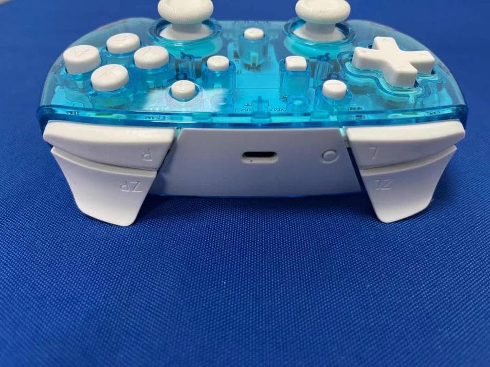
Click to zoom
Application Details
- Equipment Class
- DSS - Part 15 Spread Spectrum Transmitter
- Date of Grant
- Apr 14, 2021
- Application Purpose
- Original Equipment
- Date of Application
- Apr 14, 2021
- Equipment Note
- Wireless Controller for Nintendo Switch
- Frequency Range
- 2402.00000000 - 2480.00000000
- Country
- China
Documents & Files
Document Text
Text extracted from the exhibit documents filed with the FCC. Open a document above to read the original.
Users Manual
TURBO FUNCTION : 1. Hold Turbo button and any of A/B/X/Y/L/R/ZL/ZR to set the Auto Turbo. 2. Hold Turbo button and press any of A/B/X/Y/L/R/ZL/ZR twice to set the manual Turbo 3. Press A/B/X/Y/L/R/ZL/ZR and Turbo button to clear Turbo function; Long press Turbo button for 5 seconds to clear all the Turbo function. Turbo function without LED indication. MOTOR VIBRATION ADJUSTMENT METHOD 1. To increase motor dynamics 2. To reduce motor dynamics Precaution Before Use Note : if you haven't used the official "Switch Pro" controller before, please choose the "Switch JoyCon" and follow the connection. 1. System Settings 2. Controllers and Sensors 3. Pro Controller Wired Communication "OFF→ON” Instructions of Switch Controller Press the “Pair” button for more than two seconds Set up Successful! TROUBLESHOOTING TIPS: If the wireless controller fails to operate or operates incorrectly, please follow the steps below before seeking assistance: Verify the controller and console are both powered on. Verify the controller is within operating distance of the console. Verify the battery of the controller is fully charged. Verify the controller has been properly synchronized with the console. If, after verifying the steps above, the wireless controller still does not work correctly, please try the following: Turn the Nintendo Switch console power off. Wait for 30 seconds and then turn the console power on. Press the RESET button on the back of the wireless controller to reset the controller. Wait for 10 seconds and then resynchronize the controller with the console. User Manual Colourflow Bluetooth Pro Controller for Nintendo Switch Turbo Screenshot “-” Button Left StickRight Stick Directional-Pad HOME “+” Button Type-C Pair ZR button R button ZL button L button Product Model: BGK548 / BGK549 / BGK550 / BGK551 Guide d’utilisation Manette Bluetooth Colourflow Pro pour Nintendo Switch Turbo Capture d’écran “-” bouton Manche analogique gauche Manche analogique droit Croix directionnelle HOME “+” bouton Type-C Jumelage ZR bouton R bouton ZL bouton L bouton Modèle du produit : BGK548 / BGK549 / BGK550 / BGK551 PRODUCT SPECIFICATIONS AND CHARACTERISTICS: 1. Size: 154 * 111 * 59mm. 2. Weight: 185g + 10g. 3. Material: ABS 4. Connection method: Bluetooth. 5. Vibration: dual motor, powerful vibration mode. 6. Built-in six-axis gyroscope and acceleration function for better in-game experience. 7. Supports rapid fire function. PRECAUTION & MAINTENANCE Before use, please read the following important safety information. Following these simple guidelines will ensure trouble-free operation and optimal performance of the product and compatible electronic devices. Improper use may cause the product to stop working and may even cause serious injury to the user. This product is intended for private, non-commercial use only. Use the product for its intended purpose only. For indoor use only. Avoid exposure to external heat sources; direct, prolonged sunlight; dust; corrosive chemicals; and moisture. Do not drop the product or subject it to undue shock. This product contains small parts. Keep out of reach of children. Keep children away from the packaging material as there is a risk of suffocation. Dispose of packaging material according to applicable local regulations. Do not attempt to service or disassemble. The unit is not user-serviceable. Attempting to disassemble or service the unit could result in an electrical hazard, including injury. If you experience problems with the unit, discontinue use and contact Customer Support for assistance. Attempting to open or service the unit will void all warranties, expressed or implied. Failure to follow these directions may void the warranty. CONNECTION METHOD: [first use] * Please ensure that the console is powered on and has been upgraded to the latest version before using this product. 1. Press the Switch power button to start the console. 2. After booting up, do the following: first enter the "Handle Settings - Change Grip / Order" page, then press and hold the “pair” button for at least two seconds 3. The 4 LED lights will continue to flash. After the connection is successful, the LED lights indicate the corresponding player. [Repeated Use] 1.Press the Home button for more than 1 second to wake up the controller. 2.The switch console enters connection mode automatically when powered on, after the connection is successful, the corresponding LED light on the controller will remain lit * The controller will enter sleep mode automatically if a connection is unsuccessful for more than 10 seconds; other keys have no wake-up function. AUTOMATIC SLEEP: 1. The controller will automatically enter sleep mode when the console screen is off 2. The controller will enter sleep mode if no button is pressed for 5 minutes. (sensor does not move) * When in Bluetooth mode, press the HOME button for 5 seconds, to disconnect from the console. CONSOLE WAKE UP: If the controller is paired with the console but in sleep mode, simply press the “Home” button on the controller to wake the console. CHARGING INDICATION: 1. When the controller is turned off, LED1-LED4 flashes slowly when the power is off,the LED will turn off when fully charged. 2. Battery low voltage alarm system: current indicator flashes (quick flash) 3. The current channel indicator flashes (slow flash) when charging, and the current indicator is always on when fully charged. 4. When the pairing connection indication conflicts with the charging low power indicator, the pairing connection indicates a concern. LOW VOLTAGE ALARM : 1. If the lithium battery voltage is lower than 3.55V +0.1 V, the current channel light flashes quickly to indicate low voltage 2. If the lithium battery voltage is lower than 3.45V +0.1 V, it will automatically sleep FCC STATEMENTS: This device complies with Part 15 of the FCC Rules. Operation is subject to the following two conditions: (1) This device may not cause harmful interference, and (2) this device must …
Text truncated - open the document above for the full version.
Cover Letter(s)
iStar Technology CO., Limited 2021.04.13 Eurofins Electrical and Electronic Testing NA, Inc. 914 W. Patapsco Avenue Baltimore, MD 21230 USA RE: CONFIDENTIALITY REQUEST FOR Trademark: N/A MODEL : YS07 YS06,YS10 FCC ID: 2AV5Y-YS07 To Whom It May Concern: This letter serves as an official request for confidentiality under sections 0.457 and 0.459 of CFR 47. We have requested that the - Block Diagram - Schematics - Operational Description required to be submitted with this application be permanently withheld from public review. The above materials contain trade secrets and proprietary information not customarily released to the public. The public disclosure of these materials may be harmful to the applicant and provide unjustified benefits to its competitors. Please contact me if there is any information you may need. Sincerely, Client’s signature: Client’s name / title : Connie Huang/Manager Contact information / address: B603, B Tower, Western Silicon valley, BaoAn Road, BaoAn District, Shenzhen, China
Cover Letter(s)
iStar Technology CO., Limited 2021.04.13 Eurofins Electrical and Electronic Testing NA, Inc. 914 W. Patapsco Avenue Baltimore, MD 21230 USA RE: LETTER OF AGENT AUTHORIZATION To Whom It May Concern: We, the undersigned, hereby authorize Shenzhen BCTC Testing Co., Ltd to act on our behalf in all matters relating to application for equipment authorization, including the signing of all documents relating to these matters. We also hereby certify that no party to the application authorized hereunder is subject to the denial of benefits, including FCC benefits, pursuant to Section 5301 of the Anti-Drug Abuse Act of 1988, 21 U.S.C.853(a). This agreement expires one year from the current date. Sincerely, Client’s signature: Client’s name / title : Connie Huang Contact information / address: B603, B Tower, Western Silicon valley, BaoAn Road, BaoAn District, Shenzhen, China
Cover Letter(s)
iStar Technology CO., Limited Model Difference 2021-04-13 EUT NAME: Wireless Controller for Nintendo Switch FCC ID: 2AV5Y-YS07 MODEL : YS07 YS06,YS10 All the model are the same circuit and RF module, only for model name and color. Regards Sincerely Client’s signature Client’s name / title : Connie Huang / Manager Contact information / address: B603, B Tower, Western Silicon valley, BaoAn Road, BaoAn District, Shenzhen, China
External Photos
External Photos
ID Label/Location Info
Label & label location Size:20*10mm FCC ID: 2AV5Y-YS07 Label location
Internal Photos
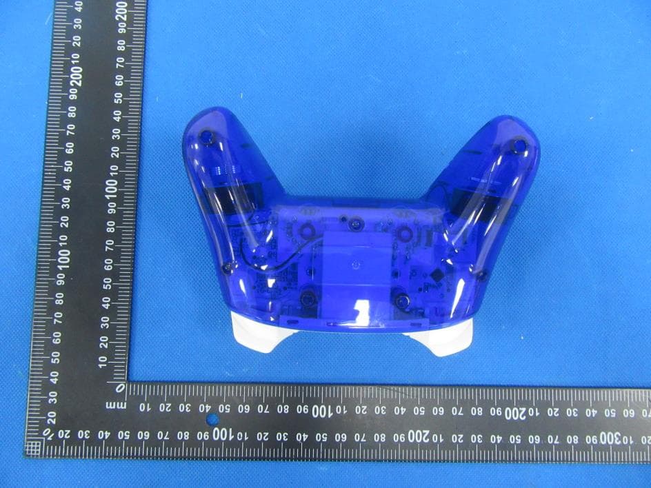
Internal Photos Antenna
RF Exposure Info
RF EXPOSURE EVALUATION METHOD FCC ID: 2AV5Y-YS07 SAR Test Exclusion Thresholds for 100 MHz – 6 GHz and ≤ 50 mm Approximate SAR Test Exclusion Power Thresholds at Selected Frequencies and Test Separation Distances are illustrated in the following Table. The 1-g and 10-g SAR test exclusion thresholds for 100 MHz to 6 GHz at test separation distances ≤ 50 mm are determined by: [(max. power of channel, including tune-up tolerance, mW)/(min. test separation distance, mm)] · [√f(GHz)] ≤ 3.0 for 1-g SAR and ≤ 7.5 for 10-g extremity SAR,where f(GHz) is the RF channel transmit frequency in GHz Power and distance are rounded to the nearest mW and mm before calculation The result is rounded to one decimal place for comparison The test exclusions are applicable only when the minimum test separation distance is ≤ 50 mm and for transmission frequencies between 100 MHz and 6 GHz. When the minimum test separation distance is < 5 mm, a distance of 5 mm is applied to determine SAR test exclusion. BT Modulation Test Channel Output Power (dBm) Limit (dBm) GFSK Low -1.815 21 GFSK Middle -2.862 21 GFSK High -1.900 21 Pi/4 DQPSK Low -1.159 21 Pi/4 DQPSK Middle -2.242 21 Pi/4 DQPSK High -1.213 21 8DPSK Low -0.547 21 8DPSK Middle -1.701 21 8DPSK High -0.594 21 max possible output power (PK,conducted):0±1dBm 0dBi logarithmic terms convert to numeric result is nearly 1. 1dBm=1.26mW 2402MHz [(max. power of channel, including tune-up tolerance, mW)/(min. test separation distance,mm)] · [√f(GHz)]=1.26/5*√2.402=0.40≤3.0 Threshold at which no SAR required is 10mw and ≤ 3.0 for 1-g SAR, Separation distance is 5mm. 2440MHz [(max. power of channel, including tune-up tolerance, mW)/(min. test separation distance,mm)] · [√f(GHz)]= 1.26/5*√2.440=0.40≤3.0 Threshold at which no SAR required is 10mw and ≤ 3.0 for 1-g SAR, Separation distance is 5mm. 2480MHz [(max. power of channel, including tune-up tolerance, mW)/(min. test separation distance,mm)] · [√f(GHz)]=1.26/5*√2.48=0.40≤3.0 Threshold at which no SAR required is 10mw and ≤ 3.0 for 1-g SAR, Separation distance is 5mm. Conclusion: No SAR is required.
Test Report
No.:BCTC/RF-EMC-005 Page 1 of 70 Edition:A.3 TEST REPORT Shenzhen BCTC Testing Co., Ltd. Report No.: BCTC2104957488E Applicant: iStar Technology CO., Limited Product Name: Wireless Controller for Nintendo Switch Model/Type Ref.: YS07 Tested Date: 2021-03-30 to 2021-04-09 Issued Date: 2021-04-09 Report No.: BCTC2104957488E No.:BCTC/RF-EMC-005 Page 2 of 70 Edition:A.3 FCC ID: 2AV5Y-YS07 The test report is effective only with both signature and specialized stamp.This result(s) shown in this report refer only to the sample(s) tested. Without written approval of Shenzhen BCTC Testing Co., Ltd, this report can’t be reproduced except in full.The tested sample(s) and the sample information are provided by the client. Product Name: Wireless Controller for Nintendo Switch Trademark: N/A Model/Type Ref.: YS07 YS06,YS10 Prepared For: iStar Technology CO., Limited Address: B603, B Tower, Western Silicon valley, BaoAn Road, BaoAn District, Shenzhen, China Manufacturer: iStar Technology CO., Limited Address: 5th floor,C2 building,Heng Feng Industrial Park, Bao An District, Shenzhen,China Prepared By: Shenzhen BCTC Testing Co., Ltd. Address: 1-2/F., Building B, Pengzhou Industrial Park, No.158, Fuyuan 1st Road, Tangwei, Fuhai Subdistrict, Bao'an District, Shenzhen, Guangdong, China Sample Received Date: 2021-03-30 Sample tested Date: 2021-03-30 to 2021-04-09 Issue Date: 2021-04-09 Report No.: BCTC2104957488E Test Standards FCC Part15.247 ANSI C63.10-2013 Test Results PASS Remark: This is Bluetooth Classic radio test report. Tested by: Approved by: Sam zeng/Project Handler Zero Zhou/Reviewer Report No.: BCTC2104957488E No.:BCTC/RF-EMC-005 Page 3 of 70 Edition:A.3 TABLE OF CONTENT Test Report Declaration Page 1. VERSION ............................................................ 5 2. TEST SUMMARY ..................................................... 6 3. MEASUREMENT UNCERTAINTY ....................................... 7 4. PRODUCT INFORMATION AND TEST SETUP............................ 8 4.1 Product Information ..................................................... 8 4.2 Test Setup Configuration ................................................ 9 4.3 Support Equipment ..................................................... 9 4.4 Channel List .......................................................... 10 4.5 Test Mode ............................................................ 10 4.6 table of parameters of text software setting ................................ 11 5. TEST FACILITY AND TEST INSTRUMENT USED ........................ 12 5.1 Test Facility ........................................................... 12 5.2 Test Instrument Used .................................................. 12 6. CONDUCTED EMISSIONS ............................................ 14 6.1 Block Diagram Of Test Setup ............................................ 14 6.2 Limit ................................................................. 14 6.3 Test procedure ........................................................ 14 6.4 EUT operating Conditions ............................................... 15 6.5 Test Result ........................................................... 16 7. RADIATED EMISSIONS .............................................. 18 7.1 Block Diagram Of Test Setup ............................................ 18 7.2 Limit ................................................................. 19 7.3 Test procedure ........................................................ 20 7.4 EUT operating Conditions ............................................... 21 7.5 Test Result ........................................................... 22 8. RADIATED BAND EMISSION MEASUREMENT AND RESTRICTED BANDS OF OPERATION .................................................. 26 8.1 Block Diagram Of Test Setup ............................................ 26 8.2 Limit ................................................................. 26 8.3 Test procedure ........................................................ 27 8.4 EUT operating Conditions ............................................... 27 8.5 Test Result ........................................................... 28 9. CONDUCTED EMISSION ............................................. 29 9.1 Block Diagram Of Test Setup ............................................ 29 9.2 Limit ................................................................. 29 9.3 Test procedure ........................................................ 29 9.4 Test Result ........................................................... 30 10. 20 DB BANDWIDTH .................................................. 39 10.1 Block Diagram Of Test Setup .......................................... 39 Report No.: BCTC2104957488E No.:BCTC/RF-EMC-005 Page 4 of 70 Edition:A.3 10.2 Limit ................................................................ 39 10.3 Test procedure ....................................................... 39 10.4 Test Result .......................................................... 40 11. MAXIMUM PEAK OUTPUT POWER .................................... 45 11.1 Block Diagram Of Test Setup .......................................... 45 11.2 Limit ................................................................ 45 11.3 Test procedure ....................................................... 45 11.4 Test Result .......................................................... 46 12. HOPPING CHANNEL SEPARATION ................................... 51 12.1 Block Diagram Of Test Setup .......................................... 51 12.2 Limit ................................................................ 51 12.3 Test procedure ....................................................... 51 12.4 Test Result .......................................................... 52 13. NUMBER OF HOPPING FREQUENCY .................................. 57 13.1 Block Diagram Of Test Setup .......................................... 57 13.2 Limit ...........................................…
Text truncated - open the document above for the full version.
Test Report
Report No.: BCTC2104957488E No.:BCTC/RF-EMC-005 Page 30 of 70 Edition:A.3 9.4 Test Result Temperature: 26°C Relative Humidity: 54% Test Voltage : DC 3.7V Remark: N/A 30MHz – 25GHz GFSK Low Channel GFSK Middle Channel GFSK High Channel Report No.: BCTC2104957488E No.:BCTC/RF-EMC-005 Page 31 of 70 Edition:A.3 Pi/4 DQPSK Low Channel Pi/4 DQPSK Middle Channel Pi/4 DQPSK High Channel Report No.: BCTC2104957488E No.:BCTC/RF-EMC-005 Page 32 of 70 Edition:A.3 8DPSK Low Channel 8DPSK Middle Channel 8DPSK High Channel Report No.: BCTC2104957488E No.:BCTC/RF-EMC-005 Page 33 of 70 Edition:A.3 GFSK Transmitting Band edge-left side GFSK Hopping Band edge-left side Report No.: BCTC2104957488E No.:BCTC/RF-EMC-005 Page 34 of 70 Edition:A.3 GFSK Transmitting Band edge-right side GFSK Hopping Band edge-right side Report No.: BCTC2104957488E No.:BCTC/RF-EMC-005 Page 35 of 70 Edition:A.3 Pi/4 DQPSK Transmitting Band edge-left side Pi/4 DQPSK Hopping Band edge-left side Report No.: BCTC2104957488E No.:BCTC/RF-EMC-005 Page 36 of 70 Edition:A.3 Pi/4 DQPSK Transmitting Band edge-right side Pi/4 DQPSK Hopping Band edge-right side Report No.: BCTC2104957488E No.:BCTC/RF-EMC-005 Page 37 of 70 Edition:A.3 8DPSK Transmitting Band edge-left side 8DPSK Hopping Band edge-left side Report No.: BCTC2104957488E No.:BCTC/RF-EMC-005 Page 38 of 70 Edition:A.3 8DPSK Transmitting Band edge-right side 8DPSK Hopping Band edge-right side Report No.: BCTC2104957488E No.:BCTC/RF-EMC-005 Page 39 of 70 Edition:A.3 10. 20 DB BANDWIDTH 10.1 Block Diagram Of Test Setup 10.2 Limit N/A 10.3 Test procedure 1. Set RBW = 30kHz. 2. Set the video bandwidth (VBW) ≥ 3 x RBW. 3. Detector = Peak. 4. Trace mode = max hold. 5. Sweep = auto couple. 6. Allow the trace to stabilize. 7. Measure the maximum width of the emission that is constrained by the frequencies associated with the two outermost amplitude points (upper and lower frequencies) that are attenuated by 6 dB relative to the maximum level measured in the fundamental emission. . Report No.: BCTC2104957488E No.:BCTC/RF-EMC-005 Page 40 of 70 Edition:A.3 10.4 Test Result Temperature: 26°C Relative Humidity: 54% Test Voltage : DC 3.7V Remark N/A Modulation Test Channel Bandwidth(MHz) GFSK Low 0.885 GFSK Middle 0.886 GFSK High 0.884 Pi/4 DQPSK Low 1.248 Pi/4 DQPSK Middle 1.247 Pi/4 DQPSK High 1.250 8DPSK Low 1.223 8DPSK Middle 1.218 8DPSK High 1.223 Test plots GFSK Low Channel
Test Report
Report No.: BCTC2104957488E No.:BCTC/RF-EMC-005 Page 41 of 70 Edition:A.3 GFSK Middle Channel GFSK High Channel Report No.: BCTC2104957488E No.:BCTC/RF-EMC-005 Page 42 of 70 Edition:A.3 Pi/4 DQPSK Low Channel Pi/4 DQPSK Middle Channel Report No.: BCTC2104957488E No.:BCTC/RF-EMC-005 Page 43 of 70 Edition:A.3 Pi/4 DQPSK High Channel 8DPSK Low Channel Report No.: BCTC2104957488E No.:BCTC/RF-EMC-005 Page 44 of 70 Edition:A.3 8DPSK Middle Channel 8DPSK High Channel Report No.: BCTC2104957488E No.:BCTC/RF-EMC-005 Page 45 of 70 Edition:A.3 11. MAXIMUM PEAK OUTPUT POWER 11.1 Block Diagram Of Test Setup 11.2 Limit FCC Part15 (15.247), Subpart C Section Test Item Limit Frequency Range (MHz) Result 15.247(b)(1) Peak Output Power 0.125 watt or 21dBm 2400-2483.5 PASS 11.3 Test procedure 1. Remove the antenna from the EUT and then connect a low RF cable from the antenna port to the spectrum. 2. Set the spectrum analyzer: RBW = 3MHz. VBW = 3MHz. Sweep = auto; Detector Function = Peak. 3. Keep the EUT in transmitting at lowest, medium and highest channel individually. Record the max value. Report No.: BCTC2104957488E No.:BCTC/RF-EMC-005 Page 46 of 70 Edition:A.3 11.4 Test Result Temperature: 26°C Relative Humidity: 54% Test Voltage : DC 3.7V Remark: N/A Modulation Test Channel Output Power (dBm) Limit (dBm) GFSK Low -1.815 21 GFSK Middle -2.862 21 GFSK High -1.900 21 Pi/4 DQPSK Low -1.159 21 Pi/4 DQPSK Middle -2.242 21 Pi/4 DQPSK High -1.213 21 8DPSK Low -0.547 21 8DPSK Middle -1.701 21 8DPSK High -0.594 21 Test plots GFSK Low Channel Report No.: BCTC2104957488E No.:BCTC/RF-EMC-005 Page 47 of 70 Edition:A.3 GFSK Middle Channel GFSK High Channel Report No.: BCTC2104957488E No.:BCTC/RF-EMC-005 Page 48 of 70 Edition:A.3 Pi/4 DQPSK Low Channel Pi/4 DQPSK Middle Channel Report No.: BCTC2104957488E No.:BCTC/RF-EMC-005 Page 49 of 70 Edition:A.3 Pi/4 DQPSK High Channel 8DPSK Low Channel Report No.: BCTC2104957488E No.:BCTC/RF-EMC-005 Page 50 of 70 Edition:A.3 8DPSK Middle Channel 8DPSK High Channel Report No.: BCTC2104957488E No.:BCTC/RF-EMC-005 Page 51 of 70 Edition:A.3 12. HOPPING CHANNEL SEPARATION 12.1 Block Diagram Of Test Setup 12.2 Limit Frequency hopping systems shall have hopping channel carrier frequencies separated by a minimum of 25 kHz or the 20 dB bandwidth of the hopping channel, whichever is greater. Alternatively, frequency hopping systems operating in the 2400-2483.5 MHz band may have hopping channel carrier frequencies that are separated by 25 kHz or two-thirds of the 20 dB bandwidth of the hopping channel, whichever is greater, provided the systems operate with an output power no greater than 0.125W. 12.3 Test procedure 1. Remove the antenna from the EUT and then connect a low RF cable from the antenna port to the spectrum. 2. Set the spectrum analyzer: RBW = 30kHz. VBW = 100kHz , Span = 2.0MHz. Sweep = auto; Detector Function = Peak. Trace = Max hold. 3. Allow the trace to stabilize. Use the marker-delta function to determine the separation between the peaks of the adjacent channels. The limit is specified in one of the subparagraphs of this Section Submit this plot. Report No.: BCTC2104957488E No.:BCTC/RF-EMC-005 Page 52 of 70 Edition:A.3 12.4 Test Result Modulation Test Channel Separation (MHz) Limit(MHz) Result GFSK Low 1.002 0.590 PASS GFSK Middle 1.002 0.591 PASS GFSK High 1.002 0.589 PASS Pi/4 DQPSK Low 1.008 0.832 PASS Pi/4 DQPSK Middle 1.000 0.831 PASS Pi/4 DQPSK High 1.000 0.833 PASS 8DPSK Low 1.002 0.815 PASS 8DPSK Middle 1.000 0.812 PASS 8DPSK High 1.000 0.815 PASS Test plots GFSK Low Channel Report No.: BCTC2104957488E No.:BCTC/RF-EMC-005 Page 53 of 70 Edition:A.3 GFSK Middle Channel GFSK High Channel Report No.: BCTC2104957488E No.:BCTC/RF-EMC-005 Page 54 of 70 Edition:A.3 Pi/4 DQPSK Low Channel Pi/4 DQPSK Middle Channel Report No.: BCTC2104957488E No.:BCTC/RF-EMC-005 Page 55 of 70 Edition:A.3 Pi/4 DQPSK High Channel 8DPSK Low Channel Report No.: BCTC2104957488E No.:BCTC/RF-EMC-005 Page 56 of 70 Edition:A.3 8DPSK Middle Channel 8DPSK High Channel Report No.: BCTC2104957488E No.:BCTC/RF-EMC-005 Page 57 of 70 Edition:A.3 13. NUMBER OF HOPPING FREQUENCY 13.1 Block Diagram Of Test Setup 13.2 Limit Frequency hopping systems in the 2400-2483.5 MHz band shall use at least 15 channels. 13.3 Test procedure 1. Remove the antenna from the EUT and then connect a low RF cable from the antenna port to the spectrum. 2. Set the spectrum analyzer: RBW = 100kHz. VBW = 300kHz. Sweep = auto; Detector Function = Peak. Trace = Max hold. 3. Allow the trace to stabilize. It may prove necessary to break the span up to sections. in order to clearly show all of the hopping frequencies. The limit is specified in one of the subparagraphs of this Section. 4. Set the spectrum analyzer: Start Frequency = 2.4GHz, Stop Frequency = 2.4835GHz. Sweep=auto; Report No.: BCTC2104957488E No.:BCTC/RF-EMC-005 Page 58 of 70 Edition:A.3 13.4 Test Result Test Plots: 79 Channels in total GFSK Pi/4 DQPSK Report No.: BCTC2104957488E No.:BCTC/RF-EMC-005 Page 59 of 70 Edition:A.3 8DPSK Report No.: BCTC2104957488E No.:BCTC/RF-EMC-005 Page 60 of 70 Edition:A.3 14. DWELL TIME 14.1 Block Diagram Of Test Setup 14.2 Limit Frequency hopping systems in the 2400-2483.5 MHz band shall use at least 15 channels. The average time of occupancy on any channel shall not be greater than 0.4 seconds within a period of 0.4 seconds multiplied by the number of hopping channels employed. Frequency hopping systems may avoid or suppress transmissions on a particular hopping frequency provided that a minimum of 15 channels are used. 14.3 Test procedure 1. Remove the antenna from the EUT and then connect a low RF cable from the antenna port to the spectrum. 2. Set spectrum analyzer span = 0. Centred on a hopping channel; 3. Set RBW = 1MHz and VBW = 3MHz.Sweep = as necessary to capture the entire dwell time per hopping channel. Set the EUT for DH5, DH3 and DH1 packet transmitting. 4. Use the marker-delta function to determine the dwell time. If this valu…
Text truncated - open the document above for the full version.
Test Report
Report No.: BCTC2104957488E No.:BCTC/RF-EMC-005 Page 67 of 70 Edition:A.3 16. EUT PHOTOGRAPHS EUT Photo 1 EUT Photo 2 Report No.: BCTC2104957488E No.:BCTC/RF-EMC-005 Page 68 of 70 Edition:A.3 17. EUT TEST SETUP PHOTOGRAPHS Conducted emissions Radiated Measurement Photos Report No.: BCTC2104957488E No.:BCTC/RF-EMC-005 Page 69 of 70 Edition:A.3 Report No.: BCTC2104957488E No.:BCTC/RF-EMC-005 Page 70 of 70 Edition:A.3 STATEMENT 1.The equipment lists are traceable to the national reference standards. 2.The test report can not be partially copied unless prior written approval is issued from our lab. 3.The test report is invalid without stamp of laboratory. 4.The test report is invalid without signature of person(s) testing and authorizing. 5.The test process and test result is only related to the Unit Under Test. 6.The quality system of our laboratory is in accordance with ISO/IEC17025. 7.If there is any objection to report, the client should inform issuing laboratory within 15 days from the date of receiving test report. Address: 1-2/F., Building B, Pengzhou Industrial Park, No.158, Fuyuan 1st Road, Tangwei, Fuhai Subdistrict, Bao'an District, Shenzhen, Guangdong, China TEL:400-788-9558 P. C.: 518103 FAX:0755-33229357 Internet:http://www.bctc-lab.com E-Mail:[email protected] ※※※※※ END ※※※※※
Test Setup Photos
Report No.: BCTC2104957488E Test Report Tel: 400-788-9558 Web: https://www.bctc-lab.com BCTC/RF-EMC-007 Ver.:A.0 Page 1 of 2 1. EUT TEST SETUP PHOTOGRAPHS Spurious emissions Report No.: BCTC2104957488E Test Report Tel: 400-788-9558 Web: https://www.bctc-lab.com BCTC/RF-EMC-007 Ver.:A.0 Page 2 of 2 Conducted emissions ※※※※※ END OF REPORT ※※※※※
Contact Information
Applicant
Connie Huang
Technical Contact
Shenzhen BCTC Testing Co., Ltd.Alan Mei
[email protected]86-755-36882589
1-2/F., Bldg B, Pengzhou Industrial Park,No.158, · Baoan District, Shenzhen, Guangdong · Chile
Test Firm
Shenzhen BCTC Testing Co., Ltd.Sally He
[email protected]15999690624
Technical Specifications
| # | Rule Parts | Frequency Range | Power Output |
|---|---|---|---|
| 1 | 15C | 2.40 GHz - 2.48 GHz | 900.00 µW |
Other Applications from iStar Technology CO., Limited
2AV5YYS07
Sep 24, 2024Wireless Game Controller
Equipment Class
DSS - Part 15 Spread Spectrum Transmitter2AV5Y-YS54
Mar 27, 2024Mini switch pro controller
Equipment Class
DTS - Digital Transmission System
2AV5YYP01
Oct 28, 2020Wireless Controller for PS4
Equipment Class
DSS - Part 15 Spread Spectrum Transmitter
2AV5YIS-M1102
Apr 21, 2020Wireless Controller for Nintendo Switch
Equipment Class
DSS - Part 15 Spread Spectrum Transmitter