2AVAHADR15-01Notebook
Venture 3 Systems LLC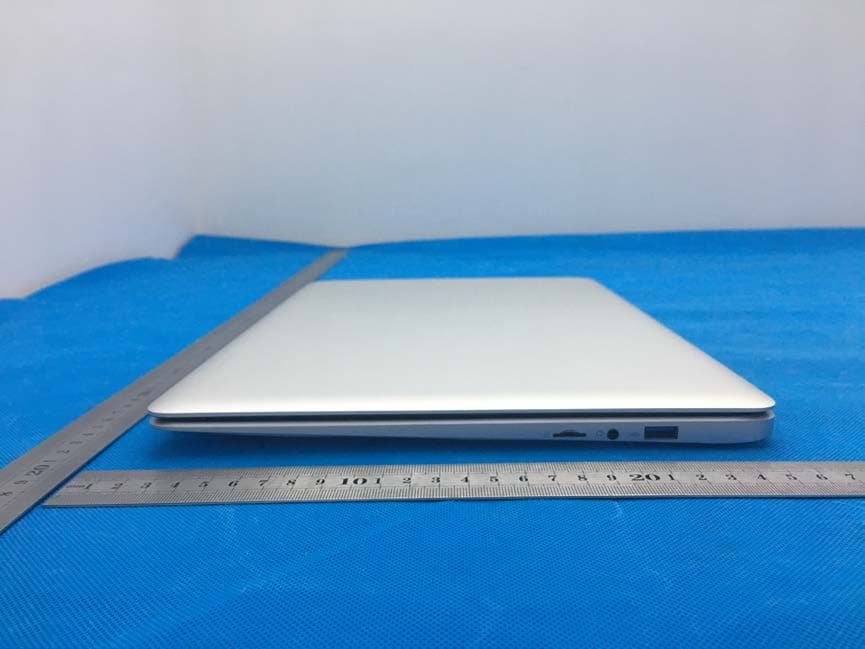
Click to zoom
Application Details
- Equipment Class
- NII - Unlicensed National Information Infrastructure TX
- Date of Grant
- Jan 02, 2020
- Application Purpose
- Original Equipment
- Date of Application
- Jan 02, 2020
- Equipment Note
- Notebook
- Frequency Range
- 5745.00000000 - 5825.00000000
- Company
- Venture 3 Systems LLC
- Country
- United States
Documents & Files
Document Text
Text extracted from the exhibit documents filed with the FCC. Open a document above to read the original.
Users Manual
Telikin Quick Start Guide Step 1: Unpack your Telikin Freedom Carefully remove all pieces from the box and place on a flat surface. Please retain all boxes and packing materials in the event that you need to invoke your warranty. The factory packaging has been specifically designed and approved by UPS to provide maximum protection during shipping. Connect the mouse to one of the USB ports on the right or left side of your Freedom Laptop (See pages 6 or 7 for locations). Look for the plugs with this symbol on them: Step 2: Know the Parts Front View Left View 1 2 3 4 1 – Webcam 2 – Touchscreen 3 – Keyboard 4 – Mouse/Touchpad 2 Right View Step 3: Charge your Telikin Freedom’s battery Connect the power adapter* to the inlet on the left side of the Freedom laptop (see page 2 for location). You can plug the power cord into a convenient wall outlet; however, to avoid damage to the computer, it is recommended that you use a UL approved power strip with a surge protector (as shown). * Use only the supplied adapter to apply power to your Telikin Freedom Laptop. Using anything other than the supplied adapter could damage your computer. 3 Notice: Charge your Telikin Freedom Laptop at least 3 hours before using it in battery mode for the first time. Step 4: Powering on your Telikin Press the power button (see page 2 for location). You can power off the computer by tapping the same power button, or by the preferred method, going to the Home screen, click Settings then click the Power Off button, it’s the last button in the right column. Once your Telikin Freedom laptop is powered on, you will see the End User License Agreement (EULA). This is an agreement that is customary for software and it states that you agree to only use the software on one computer and not make copies of the software. Please read the EULA and click the box at the bottom left to agree. Once you agree, The EULA will not be shown again and you will be taken to the Home screen. Step 5a: Connect to the Internet - Wired Tech Tip: Calling our support line while the Internet Installation Technician is at your residence will simplify the installation and activation of your internet service. If you plan to use a wireless (WiFi) Internet connection, continue on to step 5b. 4 Using the supplied network cable, connect one end to the network port at the side of the computer (see page 2 for location). Connect the other end to the network port of your cable modem or other Internet device. Note: Before proceeding to the next section, make sure your cable modem or other Internet device is powered on. At this point the Network Status icon should light up, indicating that you are connected to the internet. You can find this icon on top of the Home screen, just to the right of the time display. You may see this icon: , click on either icon to view the Network Status page where you can see what’s going on with your setup. If you are using an Ethernet cable to connect to the internet, the Wired Network section should show Ethernet Status as “Connected”. If this status is “Not Connected”, check your wired connections – alternately, if you are using DSL internet service, it may need to be activated. Please call us for help with activation. Tech Tip: If a wired network connection is available we recommend using it to ensure the best possible computing experience. Tech Tip: If you need a longer Ethernet cable, you can purchase one at a consumer electronics store. Step 5b: Connect to the Internet – Wirelessly In order to connect to the internet wirelessly, you need two things, a modem (typically installed by your Internet Service Provider - ISP) and a wireless router. The wireless router can also be provided by your ISP or obtained at any consumer electronics store. It should be noted that ISPs also may offer a wireless modem, this combines both features into one box. If you are using a separate wireless router, you will need to connect it to the modem using an Ethernet cable, check the router’s user manual, then power it on. Now back to your Telikin... On the Home screen, the Notices panel will contain a list of items that you can click to easily setup some of your personal 5 information. For now, click the “Click to set up your Network” message to view the Network/Internet Settings page. *You will not see this message if you are already connected to the Internet. This page displays the status of yours and surrounding networks. You can also get to the Network/Internet Settings page by clicking Home, then click Settings, and then click Network Settings. Since you will be using a wireless connection to the internet, take a look at the Wireless Networks section. This example shows multiple available networks, your setup may only show one. Find your wireless network name in the list and click the Connect button for this network in the Status column. The name of your wireless network and the password would be provided to you by your installer. If you are installing the router yourself, there are typically two places to check for this information: a) printed on an instruction sheet enclosed with the router, or b) printed directly on the router, typically on the bottom as shown here: The values you are looking for typically have names like SSID or ESSID, which is the network name. The other value you are interested in is the password, typically called a Key or WEP KEY as shown in the picture to the right: And here is the name as it appears in the Wireless Networks list. To connect to it, click the Connect button to the right. If your network requires a password (there’s a padlock to the left of the name), enter it in the Wireless Network Configuration screen and click Ok, Try to Connect (the password will be supplied by your internet provider – or may be on the bottom of your modem). Your computer will then attempt to connect to your wireless network. When connected, the status will change to "Connected". Write down your network name and network password on the …
Text truncated - open the document above for the full version.
Cover Letter(s)
Date: Dec. 09, 2019 Equipment Autorisation Division Federal Communications Commission 7435 Oakland Mills Road Columbia, MD 21046 FCC ID: 2AVAHADR15-01 Product Name: Notebook Request for Confidentiality Pursuant to Sections 0.457 and 0.459 of the commission’s rules, we hereby request that the following documents be held confidential: (List here the documents for which you are seeking confidentiality – for example ...) • Schematics • Block diagram • Operation description These materials contain trade secrets and proprietary information and are not customarily released to the public. The public disclosure of this information might be harmful to the company and provide unjustified benefits to our competitors. <Signature> Name: Fred Allegrezza Title: CEO Company: Venture 3 Systems LLC.
Cover Letter(s)
Date: Dec. 09, 2019 Federal Communications Commission Authorization & Evaluation Division 7345 Oakland Mills Road Columbia, Maryland 21046 RE: LETTER OF AGENT AUTHORIZATION To Whom It May Concern: We, the undersigned, hereby authorize Compliance Testing, LLC to act on our behalf in all matters relating to application for equipment authorization, including the signing of all documents relating to these matters. We also hereby certify that no party to the application authorized hereunder is subject to the denial of benefits, including FCC benefits, pursuant to Section 5301 of the Anti-Drug Abuse Act of 1988, 21 U.S.C.853(a). Sincerely, <Signature> Name: Fred Allegrezza Title: CEO Company: Venture 3 Systems LLC
Cover Letter(s)
Date: Dec. 09, 2019 Federal Communications Commission Authorization & Evaluation Division 7345 Oakland Mills Road Columbia, Maryland 21046 Authority to Act as Agent On our behalf, I appoint Shenzhen CTB Testing Technology Co., Ltd. Add: Floor 1&2, Building A, No. 26 of Xinhe Road, Xinqiao Community, Xinqiao Street, Baoan District, Shenzhen, Guangdong, China to act as our agent in the preparation of this application for equipment certification. I certify that submitted documents properly describe the device or system for which equipment certification is sought. I also certify that each unit manufactured, imported or marketed, as defined in the Federal Communications Commission’s regulations will have affixed to it a label identical to that submitted for approval with this application. For instances where our authorized agent signs the application for certification on our behalf, I acknowledge that all responsibility for complying with the terms and conditions for certification, still resides with Venture 3 Systems LLC. Add: 2805 Sterling Drive Hatfield, PA 19440, USA <Signature> Name: Fred Allegrezza Title: CEO Company: Venture 3 Systems LLC
Cover Letter(s)
Model Difference Declaration To Whom It May Concern, We, Venture 3 Systems LLC Product: Notebook Trademark: Telikin Model Number: ADR15-01, ADR15-02, ADR15-03, ADR15-04 All model’s the function, software and electric circuit are the same, only the model named different. Test sample model: ADR15-01 Please contact me if you have any question. Name: Fred Allegrezza Date: Dec. 09, 2019 Title: CEO Signature of applicant:
External Photos
M/N: ADR15-01 M/N: ADR15-01 M/N: ADR15-01 M/N: ADR15-01
ID Label/Location Info
FCC ID LABEL: Label Location: FCC ID: 2AVAHADR15-01 Product name: Notebook Model No.: ADR15-01 This device complies with Part 15 of the FCC Rules. Operation is subject to the following two conditions: (1) This device may not cause harmful interference, and (2) This device must accept any interference received, including interference that may cause undesired operation. Long:3cm Width:2cm
Internal Photos
M/N: ADR15-01 M/N: ADR15-01 Internal Ant2 Internal Ant1 M/N: ADR15-01 M/N: ADR15-01 M/N: ADR15-01
RF Exposure Info
ReportNo.:SZAWW191213004FCCID:2AVAHADR15-01Page1of87 FCCSARTestReport ClientName:Venture3SystemsLLC Address:2805SterlingDriveHatfield,PA19440,USA. ProductName:Notebook Date: Dec.26,2019 ShenzhenAnbotekComplianceLaboratoryLimited ReportNo.:SZAWW191213004FCCID:2AVAHADR15-01Page2of87 Contents 1.StatementofCompliance.......................................................................................................................................5 2.GeneralInformation.................................................................................................................................................6 2.1ClientInformation...........................................................................................................................................6 2.2DescriptionofEquipmentUnderTest(EUT).............................................................................................6 2.3DeviceCategoryandSARLimits................................................................................................................7 2.4AppliedStandard............................................................................................................................................7 2.5EnvironmentofTestSite...............................................................................................................................7 2.6TestConfiguration...........................................................................................................................................7 3.SpecificAbsorptionRate(SAR)............................................................................................................................8 3.1Introduction......................................................................................................................................................8 3.2SARDefinition.................................................................................................................................................8 4.SARMeasurementSystem....................................................................................................................................9 4.1E-FieldProbe................................................................................................................................................10 4.2DataAcquisitionElectronics(DAE)...........................................................................................................10 4.3Robot..............................................................................................................................................................11 4.4MeasurementServer...................................................................................................................................12 4.5Phantom.........................................................................................................................................................12 4.6DeviceHolder...............................................................................................................................................14 4.7DataStorageandEvaluation.....................................................................................................................15 5.TestEquipmentList..............................................................................................................................................17 6.TissueSimulatingLiquids....................................................................................................................................18 7.SystemVerificationProcedures..........................................................................................................................19 8.EUTTestingPosition............................................................................................................................................21 8.1BodyWornPosition.....................................................................................................................................21 9.MeasurementProcedures...................................................................................................................................22 9.1SpatialPeakSAREvaluation.....................................................................................................................22 9.2PowerReferenceMeasurement................................................................................................................23 9.3AreaScanProcedures................................................................................................................................23 9.4ZoomScanProcedures..............................................................................................................................24 9.5VolumeScanProcedures...........................................................................................................................25 9.6PowerDriftMonitoring.................................................................................................................................25 10.ConductedPower................................................................................................................................................26 11.SARTestResultsSummary.............................................................................................................................35 12.MeasurementUncertainty.................................................................................................................................36 AppendixA.EUTPhotosandTestSetupPhotos................................................................................................37 AppendixB.PlotsofSARSystemCheck..............................................................................................................38 AppendixC.PlotsofSARTestData...............................................................................................…
Text truncated - open the document above for the full version.
RF Exposure Info
ReportNo.:SZAWW191213004FCCID:2AVAHADR15-01Page61of87 ReportNo.:SZAWW191213004FCCID:2AVAHADR15-01Page62of87 ReportNo.:SZAWW191213004FCCID:2AVAHADR15-01Page63of87 ReportNo.:SZAWW191213004FCCID:2AVAHADR15-01Page64of87 ReportNo.:SZAWW191213004FCCID:2AVAHADR15-01Page65of87 ReportNo.:SZAWW191213004FCCID:2AVAHADR15-01Page66of87 ReportNo.:SZAWW191213004FCCID:2AVAHADR15-01Page67of87 ReportNo.:SZAWW191213004FCCID:2AVAHADR15-01Page68of87 ReportNo.:SZAWW191213004FCCID:2AVAHADR15-01Page69of87 ReportNo.:SZAWW191213004FCCID:2AVAHADR15-01Page70of87 ReportNo.:SZAWW191213004FCCID:2AVAHADR15-01Page71of87 ReportNo.:SZAWW191213004FCCID:2AVAHADR15-01Page72of87 ReportNo.:SZAWW191213004FCCID:2AVAHADR15-01Page73of87 ReportNo.:SZAWW191213004FCCID:2AVAHADR15-01Page74of87 ReportNo.:SZAWW191213004FCCID:2AVAHADR15-01Page75of87 ReportNo.:SZAWW191213004FCCID:2AVAHADR15-01Page76of87 ReportNo.:SZAWW191213004FCCID:2AVAHADR15-01Page77of87 ReportNo.:SZAWW191213004FCCID:2AVAHADR15-01Page78of87 ReportNo.:SZAWW191213004FCCID:2AVAHADR15-01Page79of87 ReportNo.:SZAWW191213004FCCID:2AVAHADR15-01Page80of87 ReportNo.:SZAWW191213004FCCID:2AVAHADR15-01Page81of87 ReportNo.:SZAWW191213004FCCID:2AVAHADR15-01Page82of87 ReportNo.:SZAWW191213004FCCID:2AVAHADR15-01Page83of87 ReportNo.:SZAWW191213004FCCID:2AVAHADR15-01Page84of87 ReportNo.:SZAWW191213004FCCID:2AVAHADR15-01Page85of87 ReportNo.:SZAWW191213004FCCID:2AVAHADR15-01Page86of87 ReportNo.:SZAWW191213004FCCID:2AVAHADR15-01Page87of87 *****ENDOFREPORT*****
Test Report
Report No.: HK1911293050-4E TEST REPORT Test report On Behalf of Venture 3 Systems LLC For Notebook Model No.: ADR15-01, ADR15-02, ADR15-03, ADR15-04 FCC ID: 2AVAHADR15-01 Prepared for : Venture 3 Systems LLC 2805 Sterling Drive Hatfield, PA 19440, USA Prepared By : SHENZHEN DEVOPS TECHNOLOGY CO., LTD. 8F-B TOWER H CHUANGXINYUNGU, #48 PAOTAI ROAD, GONGMING, GUANGMING NEW DISTRICT, SHENZHEN Date of Test: Nov. 28, 2019 ~ Dec. 05, 2019 Date of Report: Dec. 05, 2019 Report Number: HK1911293050-4E Page 1 of 141 Report No.: HK1911293050-4E TEST RESULT CERTIFICATION Applicant’s name .................. : Venture 3 Systems LLC Address .................................. : 2805 Sterling Drive Hatfield, PA 19440, USA. Manufacture's Name ............. : Shenzhen Adreamer Elite Co., Ltd. Address .................................. : Floor 4th, Fuanna industrial park,No.1 qingning road, qinghu, longhua Dist, Shenzhen, China. Product description Trade Mark: Telikin Product name ............................ : Notebook Model and/or type reference . : ADR15-01, ADR15-02, ADR15-03, ADR15-04 Standards .............................. : FCC Rules and Regulations Part 15 Subpart C Section 15.407 ANSI C63.10: 2013 This publication may be reproduced in whole or in part for non-commercial purposes as long as the Shenzhen HUAK Testing Technology Co., Ltd. is acknowledged as copyright owner and source of the material. Shenzhen HUAK Testing Technology Co., Ltd. ta kes no responsibility for and will not assume liability for damages resulting from the reader's interpretation of the reproduced material due to its placement and context. Date of Test ............................................ : Date (s) of performance of tests ............. : Nov. 28, 2019 ~ Dec. 05, 2019 Date of Issue ........................................... : Dec. 05, 2019 Test Result ............................................... : Pass Prepared by: Project Engineer Reviewed by: Project Supervisor Approved by: Technical Director Page 2 of 141 Report No.: HK1911293050-4E TABLE OF CONTENTS 1. Test Result Summary ............................................................................... 4 1.1. TEST PROCEDURES AND RESULTS ............................................................................................... 4 1.2. TEST FACILITY .................................................................................................................................. 4 1.3. MEASUREMENT UNCERTAINTY ............................................................................................................... 5 2. EUT Description ........................................................................................ 6 2.1. GENERAL DESCRIPTION OF EUT ................................................................................................... 6 2.2. OPERATION FREQUENCY EACH OF CHANNEL ........................................................................................... 7 2.3. OPERATION OF EUT DURING TESTING .................................................................................................... 7 2.4. DESCRIPTION OF TEST SETUP ....................................................................................................... 8 3. Genera Information ................................................................................... 9 3.1. TEST ENVIRONMENT AND MODE .............................................................................................................. 9 3.2. DESCRIPTION OF SUPPORT UNITS ........................................................................................................ 10 4. Test Results and Measurement Data .................................................... 11 4.1. CONDUCTED EMISSION ........................................................................................................................ 11 4.2. MAXIMUM CONDUCTED OUTPUT POWER .............................................................................................. 17 4.3. 6DB EMISSION BANDWIDTH ................................................................................................................. 25 4.4. 26DB BANDWIDTH AND 99% OCCUPIED BANDWIDTH ............................................................................ 34 4.5. POWER SPECTRAL DENSITY ................................................................................................................ 43 4.6. BAND EDGE ......................................................................................................................................... 64 4.7. SPURIOUS EMISSION ........................................................................................................................... 90 4.8. FREQUENCY STABILITY MEASUREMENT .............................................................................................. 125 4.9. UNWANTED EMISSIONS MEASUREMENT .............................................................................................. 128 4.10. ANTENNA REQUIREMENT ........................................................................................................... 139 4.11. PHOTOGRAPHS OF TEST SETUP ......................................................................................................... 140 Page 3 of 141 Report No.: HK1911293050-4E 1. Test Result Summary 1.1. TEST PROCEDURES AND RESULTS Requirement CFR 47 Section Result Antenna requirement §15.203 PASS AC Power Line Conducted Emission §15.207 PASS Maximum Conducted Output Power §15.407(a) §2.1046 PASS 6dB Emission Bandwidth §15.407(e) PASS 26dB Emission Bandwidth& 99% Occupied Bandwidth §15.407(a) §2.1049 PASS Power Spectral Density §15.407(a) PASS Band edge §15.407(a) PASS Radiated Emission §15.407(a) §2.1053 PASS Frequency Stability §15.407(g) §2.1055 PASS Note: 1. PASS: Test item meets the requirement. 2. Fail: Test item does not meet the requirement. 3. N/A: Test case does not apply to the test object. 4. The test result judgment i…
Text truncated - open the document above for the full version.
Test Setup Photos
M/N: ADR15-01 Radiated Emission test M/N: ADR15-01 Conducted Emission test
Contact Information
Applicant
Fred Allegrezza(CEO)
Test Firm
Shenzhen HUAK Testing Technology Co., Ltd.Jason Zhou
[email protected]+86-755-23029901
Technical Specifications
| # | Rule Parts | Frequency Range | Power Output |
|---|---|---|---|
| 2 | 15E | 5.75 GHz - 5.83 GHz | 14.90 mW |