2AVDM-01NFC CLR663
Lattec I/S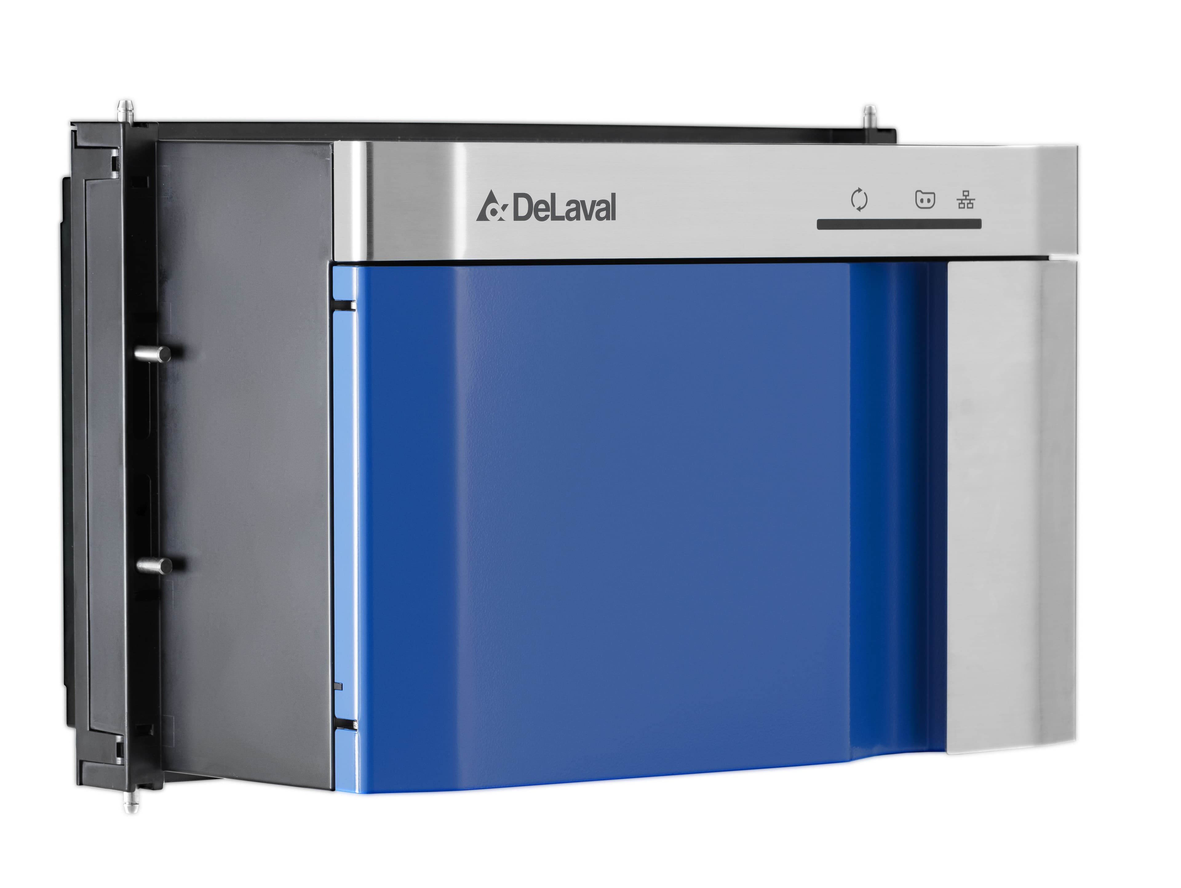
Click to zoom
Application Details
- Equipment Class
- DXX - Part 15 Low Power Communication Device Transmitter
- Date of Grant
- Jul 29, 2021
- Application Purpose
- Original Equipment
- Date of Application
- Jul 29, 2021
- Equipment Note
- NFC CLR663
- Frequency Range
- 13.56000000 - 13.56000000
- Company
- Lattec I/S
- Country
- Denmark
Documents & Files
Document Text
Text extracted from the exhibit documents filed with the FCC. Open a document above to read the original.
Users Manual
Preliminary 941322_VMS Instruction Book 2006.pdf2009-09-07 No.NameRangeDefaultDescription/optionsNo.NameRangeDefaultDescription/options 0 = no acidic cleaning0 = no acidic cleaning 1 = one alkaline, one acidic cleaning1 = one alkaline, one acidic cleaning 2 = two alkaline, one acidic cleaning2 = two alkaline, one acidic cleaning 3 = etc.3 = etc. Maintenance an calibration The following points are important to sustain correct dosing of etergents. Note that these two tasks should be performed by an authorised DeLaval service engineer. •The tubes in the peristaltic pumps should be replaced at least two times a year. •The dosing volume (P6-P8) of the detergent pumps should be checked every third month. The dosing capacity (P32-P34) may need to be adjusted. Starting cleaning or rinsing from the touch screen Note: Any ongoing backflush process must first be finished before cleaning or rinsing can be started. 1. Ensure that the milking station is in manual mode. 2. Remove any cow that might be in the milking station. After treatment window Note: Both gates should be closed to prevent a cow from entering before the system cleaning has been started. Closing and opening gates is done in the Stall control window. 3. Press the tab After Treatment on the touch screen to display the After treatment window. 4. In the After treatment window, press the Cleaning and Rinsing button. This will open the Cleaning and rinsing window. DeLaval Herd Navigator™ precision analytics 100 Instruction Book © DeLaval 2021.2800008901 2021-05-10, Version 3Original instruction Preliminary 941322_VMS Instruction Book 2006.pdf2009-09-07 No.NameRangeDefaultDescription/optionsNo.NameRangeDefaultDescription/options 0 = no acidic cleaning0 = no acidic cleaning 1 = one alkaline, one acidic cleaning1 = one alkaline, one acidic cleaning 2 = two alkaline, one acidic cleaning2 = two alkaline, one acidic cleaning 3 = etc.3 = etc. Maintenance an calibration The following points are important to sustain correct dosing of etergents. Note that these two tasks should be performed by an authorised DeLaval service engineer. •The tubes in the peristaltic pumps should be replaced at least two times a year. •The dosing volume (P6-P8) of the detergent pumps should be checked every third month. The dosing capacity (P32-P34) may need to be adjusted. Starting cleaning or rinsing from the touch screen Note: Any ongoing backflush process must first be finished before cleaning or rinsing can be started. 1. Ensure that the milking station is in manual mode. 2. Remove any cow that might be in the milking station. After treatment window Note: Both gates should be closed to prevent a cow from entering before the system cleaning has been started. Closing and opening gates is done in the Stall control window. 3. Press the tab After Treatment on the touch screen to display the After treatment window. 4. In the After treatment window, press the Cleaning and Rinsing button. This will open the Cleaning and rinsing window. Preliminary 941322_VMS Instruction Book 2006.pdf2009-09-07 No.NameRangeDefaultDescription/optionsNo.NameRangeDefaultDescription/options 0 = no acidic cleaning0 = no acidic cleaning 1 = one alkaline, one acidic cleaning1 = one alkaline, one acidic cleaning 2 = two alkaline, one acidic cleaning2 = two alkaline, one acidic cleaning 3 = etc.3 = etc. Maintenance an calibration The following points are important to sustain correct dosing of etergents. Note that these two tasks should be performed by an authorised DeLaval service engineer. •The tubes in the peristaltic pumps should be replaced at least two times a year. •The dosing volume (P6-P8) of the detergent pumps should be checked every third month. The dosing capacity (P32-P34) may need to be adjusted. Starting cleaning or rinsing from the touch screen Note: Any ongoing backflush process must first be finished before cleaning or rinsing can be started. 1. Ensure that the milking station is in manual mode. 2. Remove any cow that might be in the milking station. After treatment window Note: Both gates should be closed to prevent a cow from entering before the system cleaning has been started. Closing and opening gates is done in the Stall control window. 3. Press the tab After Treatment on the touch screen to display the After treatment window. 4. In the After treatment window, press the Cleaning and Rinsing button. This will open the Cleaning and rinsing window. EU Declaration of Conformity - DeLaval Herd Navigator™ precision analytics 100.....................5 Safety precautions..............................................................................................................................7 nDeLaval Herd Navigator™ precision analytics 100 1 Foreword...........................................................................................................................7 2 Disclaimer.........................................................................................................................7 3 Precautionary statements.................................................................................................7 4 Safety regulations.............................................................................................................8 4.1 Safety regulations - General.............................................................................8 5 Safe and healthy work routines.........................................................................................9 6 Consumables..................................................................................................................10 7 Compliance with national regulations..............................................................................10 7.1 Compliance Statement.................................................................................... 10 7.2 ISED Compliance Statement..........................................................................11 8 Type plate...........................…
Text truncated - open the document above for the full version.
Cover Letter(s)
053019-02a Request for Modular/Limited Modular Approval Date: January 4, 2021 Subject: Manufacturer’s Declaration for ☐ - Modular Approval ☐ - Split Modular Approval ☒ - Limited Modular Approval ☐ - Limited Split Modular Approval Confidentiality Request for: ______2AVDM-01______ 8 Basic Requirements – FCC Part 15.212(a)(1) For Items Marked “NO(*)”, the Limited Module Description Must be Filled Out on the Following Pages Modular Approval Requirement Requirement Met 1. The modular transmitter must have its own RF shielding. This is intended to ensure that the module does not have to rely upon the shielding provided by the device into which it is installed in order for all modular transmitter emissions to comply with FCC limits. It is also intended to prevent coupling between the RF circuitry of the module and any wires or circuits in the device into which the module is installed. Such coupling may result in non-compliant operation. The physical crystal and tuning capacitors may be located external to the shielded radio elements. 15.212(a)(1)(i) ☐ - YES ☒ - NO(*) Details: The NCF module contains no metal shield. The NFC module RF field exposure is limited. All compliant tests are performed the module integrated in “ Delaval Herd Navigator precision analytics 100”. 2. The modular transmitter must have buffered modulation/data inputs (if such inputs are provided) to ensure that the module will comply with FCC requirements under conditions of excessive data rates or over-modulation. 15.212(a)(1)(ii) ☒ - YES ☐ - NO(*) Details: Data to the modulation circuit is buffered as described in the operational description provided with the application 3. The modular transmitter must have its own power supply regulation on the module. This is intended to ensure that the module will comply with FCC requirements regardless of the design of the power supplying circuitry in the device into which the module is installed. 15.212(a)(1)(iii) ☐ - YES ☒ - NO(*) Details: The NFC module is connected to the internal power regulation in “ Delaval Herd Navigator precision analytics 100”. 4. The modular transmitter must comply with the antenna and transmission system requirements of §§ 15.203, 15.204(b), 15.204(c), 15.212(a), and 2.929(b). The antenna must either be permanently attached or employ a ‘‘unique’’ antenna coupler (at all connections between the module and the antenna, including the cable). The ‘‘professional installation’’ provision of § 15.203 is not applicable to modules but can apply to limited modular approvals under paragraph 15.212(b). 15.212(a)(1)(iv) ☒ - YES ☐ - NO(*) Details: The antenna is an integrated part of the NFC module. 5. The modular transmitter must be tested in a stand-alone configuration, i.e., the module must not be inside another device during testing. This is intended to demonstrate that the module is capable of complying with Part 15 emission limits regardless of the device into which it is eventually installed. Unless the transmitter module will be battery powered, it must comply with the AC line conducted requirements found in Section 15.207. AC or DC power lines and data input/output lines connected to the module must not contain ferrites, unless they will be marketed with the module (see Section 15.27(a)). The length of these lines shall be length typical of actual use or, if that length is unknown, at least 10 centimeters to insure that there is no coupling between the case of the module and supporting equipment. Any accessories, peripherals, or support equipment connected to the module during testing shall be unmodified or commercially available (see Section 15.31(i)). 15.212(a)(1)(v) ☐ - YES ☒ - NO(*) Details: The module is only for use in “Delaval Herd Navigator Precision Analytics 100”, and not for sale to third parties. 053019-02a Modular Approval Requirement Requirement Met 6. The modular transmitter must be labeled with its own FCC ID number, or use an electron display (see KDB Publication 784748). If using a permanently affixed label with its own FCC ID number, if the FCC ID is not visible when the module is installed inside another device, then the outside of the device into which the module is installed must also display a label referring to the enclosed module. This exterior label can use wording such as the following: “Contains Transmitter Module FCC ID: XYZMODEL1” or “Contains FCC ID: XYZMODEL1.” Any similar wording that expresses the same meaning may be used. The Grantee may either provide such a label, an example of which must be included in the application for equipment authorization, or, must provide adequate instructions along with the module which explain this requirement. In the latter case, a copy of these instructions must be included in the application for equipment authorization. If the modular transmitter uses an electronic display of the FCC identification number, the information must be readily accessible and visible on the modular transmitter or on the device in which it is installed. If the module is installed inside another device, then the outside of the device into which the module is installed must display a label referring to the enclosed module. This exterior label can use wording such as the following: “Contains FCC certified transmitter module(s).” Any similar wording that expresses the same meaning may be used. The user manual must include instructions on how to access the electronic display. A copy of these instructions must be included in the application for equipment authorization. 15.212(a)(1)(vi) ☒ - YES ☐ - NO(*) Details: There is a label on the module as shown in the labeling exhibit filed with this application. Host specific labeling instructions are shown on the type label. 7. The modular transmitter must comply with all specific rule or operating requirements applicable to the transmitter, including all the conditions provided in the integration instructions by the grantee. A copy of these instructions must be included in the applic…
Text truncated - open the document above for the full version.
Cover Letter(s)
2020-01-04 Lattec I/S Blytækkervej 10 3400 Hillerød Denmark NFC product applications The NFC CLRC663 module is only for use by grantee in “Delaval Herd Navigator TM precision analytics 100”, and not intended for sale to third parties. John Slaaby Latte I/S
Cover Letter(s)
Request for Confidentiality Date: December 15, 2020 Subject: Confidentiality Request for: FCC ID: 2AVDM-01 / IC: 25745-01 Pursuant to FCC 47 CFR 0.457(d) and 0.459 and IC RSP-100, Section 12.4, the applicant requests that a part of the subject FCC application be held confidential. Type of Confidentiality Requested Exhibit ☐ Short Term ☒ Permanent Block Diagrams ☒ Short Term External Photos ☒ Short Term ☐ Permanent * 1 Internal Photos ☐ Short Term ☒ Permanent Operation Description/Theory of Operation ☐ Short Term ☒ Permanent Parts List & Placement/BOM ☐ Short Term ☐ Permanent Tune-Up Procedure ☐ Short Term ☒ Permanent Schematics ☒ Short Term Test Setup Photos ☒ Short Term ☐ Permanent * 3 User’s Manual Lattec I/S has spent substantial effort in developing this product and it is one of the first of its kind in industry. Having the subject information easily available to "competition" would negate the advantage they have achieved by developing this product. Not protecting the details of the design will result in financial hardship. Permanent Confidentiality: The applicant requests the exhibits listed above as permanently confidential be permanently withheld from public review due to materials that contain trade secrets and proprietary information not customarily released to the public. Short-Term Confidentiality: The applicant requests the exhibits selected above as short term confidential be withheld from public view for a period of 180 days from the date of the Grant of Equipment Authorization and prior to marketing. This is to avoid premature release of sensitive information prior to marketing or release of the product to the public. Applicant is also aware that they are responsible to notify ACB in the event information regarding the product or the product is made available to the public before the requested period has expired. ACB will then release the documents listed above for public disclosure pursuant to FCC Public Notice DA 04-1705. NOTE for Industry Canada Applications: IC currently only distinguishes Permanent Confidentiality exhibits as shown above. Short Term confidentiality is not considered applicable to IC applications. Sincerely, By: __________John Slaaby______________ (Signature/Title 2 ) (Print name) 1 - The asterisked items (*) require further information to be provided to ACB before permanent confidentiality will be extended to these exhibits. Please refer to FCC KDB 726920 and the specific Document link for D01 found at: https://apps.fcc.gov/oetcf/kdb/forms/FTSSearchResultPage.cfm?switch=P&id=41731 and review section II, 3) regarding specific information that must accompany these requests. 2 - Must be signed by applicant contact given for applicant on the FCC site, or by the authorized agent if an appropriate authorized agent letter has been provided. Letters should be placed on appropriate letterhead.
ID Label/Location Info
Lattec Version 4 2021-01-04 HN100 Label location The HN100 has two identical type labels: 1 of 2, on the backside of Main Unit: Version 5 2021-07-30 Lattec Version 4 2021-01-04 2 of 2, on the Inner Cover top: NFC CLR663 module label: PMN: NFC CLRC663 HVIN:3 FCC ID: 2AVDM-01 IC: 25745-01 Version 5 2021-07-30
Internal Photos
HN100 – Internal Photos Herd Navigator™ Precision Analytics 100 (HN100) Comment Image HN100 front. Part number 60091513. Full product name for HN100: Herd Navigator Precision Analytics 100 HN100 back HN100 back door removed. HN100 back. Grey shield removed. Positions for the 4 NFC units (blue arrow). Two external connections: • 24VDC supply (green connector in top). • Ethernet in the top. NFC0 NFC1 NFC2 NFC3 4 NFC units in a daisy chain. Part numbers: 60091735, 60091736, 60091737, 60091738 NFC unit. The electronic is inside the antenna. HN100 installed in a Milking robot, VMS300.
Test Report
REPORT Testing & Reliability Services Accredited by DANAK under registration number 563 to testing. TEST: Testing laboratory (DS/EN ISO/IEC 17025) FCC reg. no.: DK0002 ISED CAB identifier: DK0001 A. C. Meyers Vænge 15 2450 Copenhagen SV Denmark +45 7070 1499 [email protected] Date Reference Page 2021-02-04 P19-0186-1 rev. 2 1 (36) DANAK is the national accreditation body in Denmark in compliance with EU regulation No. 765/2008. DANAK participates in the multilateral agreements for testing and calibration under European co-operation for Accreditation (EA) and under International Laboratory Accreditation Cooperation (ILAC) based on peer-evaluation. Accredited test reports issued by laboratories accredited by DANAK are recognized cross border by members of EA and ILAC equal to test reports issued by these members’ accredited laboratories. The use of the accreditation mark on test reports, documents that the service is provided as an accredited service under the company's DANAK accreditation. EKTOS Testing & Reliability Services A/S Test Report of DeLaval Herd Navigator™ precision analytics 100 FCC ID: 2AVDM-01 ISED ID: 25745-01 according to FCC 47 CFR, Part 15 Subpart C 15.225 Operation within the band 13.110 – 14.010 MHz and ISED RSS-210 Annex B.6 Band 13.110 – 14.010 MHz Performed by Examined by Søren Søltoft Senior EMC Engineer David Busk Lab. Manager, M. Sc. EE. REPORT Date Reference Page FCC ID: 2AVDM-01 2021-02-04 P19-0186-1 rev. 2 2 (36) ISED ID: 25745-01 EKTOS Testing & Reliability Services A/S Report no.: P19-0186-1 rev. 2 Report date: 2021-02-04 Test started: 2019-10-30 Test ended: 2020-01-15 Test laboratory: EKTOS TRS A/S A. C. Meyers Vænge 15 2450 Copenhagen SV Denmark Client: Lattec I/S Blytækkervej 10 3400 Hillerød Denmark Contact person: Søren Søltoft Contact person: John Slaaby Facility reg. no. FCC Designation number: DK0002 ISED CAB identifier: DK0001 Test specimen: DeLaval Herd Navigator™ precision analytics 100 Test specification: P19-0186-1 rev. 1 supersedes P19-0186-1 issued 2020-01-13. Changes: Added 99% Occupied bandwidth measurement. P19-0186-1 rev. 2 supersedes P19-0186-1 rev. 1 issued 2020-01-15. Changes: Report reissued. FCC 47 CFR Part 15 Subpart C 15.225 Operation within the band 13.11 – 14.01 MHz. ISED RSS-210 Annex B.6 Band 13.110 – 14.010 MHz. The tests relevant for the test specimens are listed in section 1.1. Documentation: This test report must always be reproduced in full; reproduction of an excerpt only is subject to written approval of the testing laboratory. The complete test documentation is archived for 10 years at the testing laboratory. Test results: The test specimen complies with relevant parts of the test specifications. The test results relate only to the specimen tested. Test personnel: Søren Søltoft David Busk REPORT Date Reference Page FCC ID: 2AVDM-01 2021-02-04 P19-0186-1 rev. 2 3 (36) ISED ID: 25745-01 EKTOS Testing & Reliability Services A/S CONTENTS 1 SUMMARY ......................................................................................................... 4 1.1 Test plan .................................................................................................................................... 4 1.2 Test specimens ......................................................................................................................... 5 1.1 Auxiliary Equipment................................................................................................................... 6 1.2 I/O port to test specimen ........................................................................................................... 6 2 TESTS ................................................................................................................ 7 2.1 Field strength of fundamental emission .................................................................................... 7 2.2 Field strength of in band emission ............................................................................................ 8 2.3 Emission outside the 13.110-14.010 MHz band (below 30 MHz) ........................................... 12 2.4 Emission outside the 13.110-14.010 MHz band (above 30 MHz) .......................................... 16 2.5 Frequency stability versus temperature .................................................................................. 25 2.6 Frequency stability versus supply voltage .............................................................................. 26 2.7 Antenna requirement ............................................................................................................... 27 2.8 AC Conducted emission .......................................................................................................... 28 2.9 Occupied bandwidth ................................................................................................................ 34 3 MEASURING UNCERTAINTIES ...................................................................... 36 Appendix issued in separate report 1 Photos of test setups and equipment. REPORT Date Reference Page FCC ID: 2AVDM-01 2021-02-04 P19-0186-1 rev. 2 4 (36) ISED ID: 25745-01 EKTOS Testing & Reliability Services A/S 1 SUMMARY See Appendix 1 for photos. Emission measurements as specified below have been performed. 1.1 Test plan Standard Name of the test Results FCC 47 CFR Part 15C 15.225 Operation within the band 13.110 – 14.010 MHz PASSED RSS 210 Issue 9, Aug 2016 (Amendment) B.6 Band 13.110 – 14.010 MHz PASSED 15.225 (a) RSS 210 B.6 (a) Field strength of fundamental emission PASSED 15.225 (b), (c) RSS 210 B.6 (b), (c) Field strength of in band emission PASSED 15.225 (d) RSS 210 B.6 (d) Emission outside frequency band PASSED 15.225 (e) RSS 210 B.6 Frequency stability PASSED 15.203 RSS-Gen 6.8 Antenna requirement PASSED 15.207 (a) RSS-Gen 8.8 AC conducted emission PASSED 15.215 (c) RSS-Gen 6.7 Occupied bandwidth PASSED PASSED The test was performed and the test specimen…
Text truncated - open the document above for the full version.
Test Setup Photos
REPORT Date Reference Page FCC ID: 2AVDM-01 2021-02-04 P19-0186-1 rev. 2 1 (4) ISED ID: 25745-01 Appendix 1 EKTOS Testing & Reliability Services A/S Appendix 1 Photos Photo 1. HN100 Front view. Photo 2. NFC module. Top view. REPORT Date Reference Page FCC ID: 2AVDM-01 2021-02-04 P19-0186-1 rev. 2 2 (4) ISED ID: 25745-01 Appendix 1 EKTOS Testing & Reliability Services A/S Photo 3. NFC module. Bottom view. Photo 4. Frequency stability under temperature variation test set up. Occupied bandwidth -20 dB test set up. REPORT Date Reference Page FCC ID: 2AVDM-01 2021-02-04 P19-0186-1 rev. 2 3 (4) ISED ID: 25745-01 Appendix 1 EKTOS Testing & Reliability Services A/S Photo 5. Radiated emission test setup at OATS. 9 kHz – 30 MHz Photo 6. Radiated emission test setup in SAC. 9 kHz – 30 MHz. Photo 7. Radiated emission test setup in SAC. 30 - 200 MHz. REPORT Date Reference Page FCC ID: 2AVDM-01 2021-02-04 P19-0186-1 rev. 2 4 (4) ISED ID: 25745-01 Appendix 1 EKTOS Testing & Reliability Services A/S Photo 8. Radiated emission test setup in SAC. 200 - 1000 MHz. Photo 9. AC Conducted emission test set up.
Contact Information
Applicant
John Slaaby(Senior Project Manager)
Technical Contact
Test Firm
EKTOS Testing & Reliability Services A/S (EKTOS TRHenrik Brosbol
[email protected]+45 3114 0428
Technical Specifications
| # | Rule Parts | Frequency Range | Power Output |
|---|---|---|---|
| 1 | 15C | 13.56 MHz - 13.56 MHz | - |