2AVDQ-ESKY008085Remote Controller
Shenzhen Zonda Hobby Co.,Ltd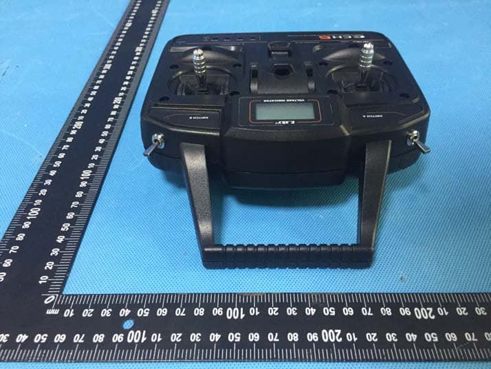
Click to zoom
Application Details
- Equipment Class
- DSS - Part 15 Spread Spectrum Transmitter
- Date of Grant
- Jan 07, 2020
- Application Purpose
- Original Equipment
- Date of Application
- Jan 07, 2020
- Equipment Note
- Remote Controller
- Frequency Range
- 2406.00000000 - 2475.00000000
- Company
- Shenzhen Zonda Hobby Co.,Ltd
- Country
- China
Documents & Files
Document Text
Text extracted from the exhibit documents filed with the FCC. Open a document above to read the original.
Users Manual
User Manual Remote Controller ESKY008085 Esky FCC ID: 2AVDQ-ESKY008085 Shenzhen Zonda Hobby Co.,Ltd Rm 609, Block A, Dachong Business Center, #9678 Shennan Rd. Nanshan District, Shenzhen, China Elevator Trim Lever Aileron Trim Lever Reverse Switches Charging Indicator Power Switch Left Control Stick Throttle Trim Lever Rudder Trim Lever Right Control Stick Throttle Cut SwitchSwitch Beginner / Experienced Mode ECH6 Transmitter (RTF Version) - Left hand throttle Mode2 LCD Voltage Indicator: In the power-on state, the current transmitter battery voltage is displayed. Beginner/Experienced Mode Switch: LO is Beginner Mode, HI is Experienced Mode. Throttle Cut Switch: Red dot position is ON, green dot position is OFF. Left Control Stick: UP and DOWN are Throttle Control, Left and Right are Rudder Control. Right Control Stick: UP and DOWN are Elevator Control, Left and Right are Aileron Control. Elevator Trim Lever: Fine tuning the Pitch Control Rudder Trim Lever: Fine tuning the Rudder Control Throttle Trim Lever: Fine tuning the Throttle Control Aileron Trim Lever: Fine tuning the Aileron Control Power Switch: Push up to power on, push down to power off. Charging Indicator: ECH6 transmitter (RTF version) uses Alkaline Battery, so the transmitter charging function is not available. (Transmitter charging function is only available to LiPO batteries and NiMH batteries) Reverse Switches: Control direction of movement of servos connected to the receiver. AIL Reverse Switch: Control direction of movement for Channel 1, NOR is Normal, REV is Reverse. ELE Reverse Switch: Control direction of movement for Channel 2, NOR is Normal, REV is Reverse. THR Reverse Switch: Control direction of movement for Channel 3, NOR is Normal, REV is Reverse. RUD Reverse Switch: Control direction of movement for Channel 4, NOR is Normal, REV is Reverse. Caution: Using the THR mode prudently. Incorrect setting can cause left stick (throttle stick work vertically) operate reversely (the aircraft motor will operate maximally when left stick push to bottom). Changing the throttle control direction only affect the signal sent from the controller, and it will not affect the motor operate direction. 8 EN LCD Voltage Indicator Mode 2 ECH6 Transmitter Control Direction - Left hand throttle Mode2 Push the “Left Stick” up, the aircraft motor speeds up to make the aircraft go faster. When pushing the “Left Stick” down, the aircraft motor speeds down and slow down the aircraft. This procedure is Throttle Control. Push the “Left Stick” left or right to point the nose of the aircraft left or right. The rudder stick is also used to steer the aircraft left and right while taxiing on the ground. This procedure is Rudder Control. Push the “Right Stick” up to make the aircraft go down. Push the “Right Stick” down to make the aircraft go up. This procedure is Elevator Control. Push the “Right Stick” left to make the aircraft roll or bank left, Push the “Right Stick” right to make the aircraft roll or bank right. This procedure is Aileron Control. EN Mode 2 Mode 2 Mode 2 9 ECH6 Transmitter (RTF Version) - Right hand throttle Mode1 10 EN LCD Voltage Indicator: In the power-on state, the current transmitter battery voltage is displayed. Beginner/Experienced Mode Switch: LO is Beginner Mode, HI is Experienced Mode. Throttle Cut Switch: Red dot position is OFF, green dot position is ON. Left Control Stick: UP and DOWN are Elevator Control, Left and Right are Rudder Control. Right Control Stick: UP and DOWN are Throttle Control, Left and Right are Aileron Control. Elevator Trim Lever: Fine tuning the Pitch Control Rudder Trim Lever: Fine tuning the Rudder Control Throttle Trim Lever: Fine tuning the Throttle Control Aileron Trim Lever: Fine tuning the Aileron Control Power Switch: Push up to power on, push down to power off. Charging Indicator: ECH6 transmitter (RTF version) uses Alkaline Battery, so the transmitter charging function is not available. (Transmitter charging function is only available to LiPO batteries and NiMH batteries) Reverse Switches: Control direction of movement of servos connected to the receiver. AIL Reverse Switch: Control direction of movement for Channel 1, NOR is Normal, REV is Reverse. ELE Reverse Switch: Control direction of movement for Channel 2, NOR is Normal, REV is Reverse. THR Reverse Switch: Control direction of movement for Channel 3, NOR is Normal, REV is Reverse. RUD Reverse Switch: Control direction of movement for Channel 4, NOR is Normal, REV is Reverse. Caution: Using the THR mode prudently. Incorrect setting can cause right stick (throttle stick) operate reversely (the aircraft motor will operate maximally when left stick push to bottom). Changing the throttle control direction only affect the signal sent from the controller, and it will not affect the motor operate direction. Throttle Trim Lever Aileron Trim Lever Reverse Switches Charging Indicator Power Switch Left Control Stick Elevator Trim Lever Rudder Trim Lever Right Control Stick SwitchThrottle Cut Switch Beginner / Experienced Mode LCD Voltage Indicator ECH6 Transmitter Control Direction - Right hand throttle Mode1 11 EN Mode 1 Push the “Right Stick” up, the aircraft motor speeds up to make the aircraft go faster. When pushing the “Right Stick” down, the aircraft motor speeds down and slow down the aircraft. This procedure is Throttle Control. Push the “Left Stick” left or right to point the nose of the aircraft left or right. The rudder stick is also used to steer the aircraft left and right while taxiing on the ground. This procedure is Rudder Control. Push the “Left Stick” up to make the aircraft go down. Push the “Left Stick” down to make the aircraft go up. This procedure is Elevator Control. Push the “Right Stick” left to make the aircraft roll or bank left, Push the “Right Stick” right to make the aircraft roll or bank right. This procedure is Aileron Control. Mode 1 Mode 1 Mode 1 FCC Warning: This device complies with part 15 of the F…
Text truncated - open the document above for the full version.
Cover Letter(s)
Shenzhen Zonda Hobby Co.,Ltd Date: Jan. 02, 2020 Federal Communications Commission Authorization and Evaluation Division Confidentiality Request regarding application for certification of FCC ID: 2AVDQ-ESKY008085 Pursuant to Sections 0.457 and 0.459 of the Commission’s Rules, we hereby request confidential treatment of information accompanying this application as outlined below: Exhibit Type File Name Schematics Block Diagram Operational Description Schematics.pdf Block Diagram.pdf Operational Description.pdf The above materials contain trade secrets and proprietary information not customarily released to the public. The public disclosure of these materials may be harmful to the applicant and provide unjustified benefits to its competitors. The applicant understands that pursuant to Section 0.457 of the Rules, disclosure of this application and all accompanying documentation will not be made before the date of the Grant for this application. Sincerely, Shenzhen Zonda Hobby Co.,Ltd Signature James King / General Manager Typed name and Title
Cover Letter(s)
Shenzhen Zonda Hobby Co.,Ltd Date: 1/2/2020 To: Federal Communications Commission 7435 Oakland Mills Road Columbia, MD To Whom It May Concern: We, Shenzhen Zonda Hobby Co.,Ltd, state that our device, FCC ID: 2AVDQ-ESKY008085, has a battery, but the battery will not be placed in the battery compartment when delivery, the label is visible to the users as they purchase the products and install the battery. The back cover can be moved away, there is not enough space to print FCC ID label in surface of products, so the label has to be placed in battery compartment. Sincerely, Signature [James King (Name)] [General Manager (Title)] [Shenzhen Zonda Hobby Co.,Ltd. (Company name)]
Cover Letter(s)
Shenzhen Zonda Hobby Co.,Ltd FCC ID: 2AVDQ-ESKY008085 POWER OF ATTORNEY Date: Jan. 02, 2020 Federal Communications Commission Authorization and Evaluation Division 7435 Oakland Mills Road Columbia, MD 21046 To Whom It May Concern: We, the undersigned, hereby authorize Waltek Services (ShenZhen) Co., Ltd. (Philo Zhong) on our behalf, to apply to the Federal Communications Commission on our equipment. Any and all acts carried out by Waltek Services (ShenZhen) Co., Ltd. (Philo Zhong) on our behalf shall have the same effect as acts of our own. This authorization expires on Jan. 01, 2021. This is to advise that we are in full compliance with the Anti-Drug Abuse Act. We, Shenzhen Zonda Hobby Co.,Ltd are not subject to a denial of federal benefits pursuant to Section 5301 of the Anti-Drug Act of 1988, 21 USC853a, and no party to the application is subject to a denial of federal benefits pursuant to that section. Sincerely, Shenzhen Zonda Hobby Co.,Ltd Signature James King / General Manager Typed name and Title
External Photos
Appendix-ESKY008085-Photos Page 3 of 23 EUT – External View Model ESKY008085 FCC ID: 2AVDQ-ESKY008085 Appendix-ESKY008085-Photos Page 4 of 23 Appendix-ESKY008085-Photos Page 5 of 23 Appendix-ESKY008085-Photos Page 6 of 23
ID Label/Location Info
ESKY008085 Label Sample and Location
Internal Photos
Appendix-ESKY008085-Photos Page 7 of 23 EUT – Internal View Model ESKY008085 FCC ID: 2AVDQ-ESKY008085 Appendix-ESKY008085-Photos Page 8 of 23 2.4G ANT 1. 2.4G ANT 2. Appendix-ESKY008085-Photos Page 9 of 23 Appendix-ESKY008085-Photos Page 10 of 23 Appendix-ESKY008085-Photos Page 11 of 23
Internal Photos
Appendix-ESKY008085-Photos Page 12 of 23 Appendix-ESKY008085-Photos Page 13 of 23 Appendix-ESKY008085-Photos Page 14 of 23 Appendix-ESKY008085-Photos Page 15 of 23 Appendix-ESKY008085-Photos Page 16 of 23
Internal Photos
Appendix-ESKY008085-Photos Page 17 of 23 Appendix-ESKY008085-Photos Page 18 of 23 Appendix-ESKY008085-Photos Page 19 of 23 Appendix-ESKY008085-Photos Page 20 of 23 Appendix-ESKY008085-Photos Page 21 of 23
Internal Photos
Appendix-ESKY008085-Photos Page 22 of 23 Appendix-ESKY008085-Photos Page 23 of 23 ======End======
RF Exposure Info
Waltek Services (Shenzhen) Co.,Ltd. Page 1 of 58 http://www.waltek.com.cn SAR TEST REPORT Reference No. ................... : WTD19S12088864W001 FCC ID ................................ : 2AVDQ-ESKY008085 Applicant ........................... : Shenzhen Zonda Hobby Co.,Ltd Address ............................. : Rm 609, Block A, Dachong Business Center, #9678 Shennan Rd. Nanshan District, Shenzhen, China Manufacturer .................... : The same as above Address ............................. : The same as above Product .............................. : Remote Controller Model(s). ............................ : ESKY008085 Brand Name ...................... : Esky Standards .......................... : FCC 47 CFR Part2(2.1093) ANSI/IEEE C95.1-2006 IEEE 1528-2013 & Published RF Exposure KDB Procedures Date of Receipt sample .... : 2019-12-20 Date of Test ....................... : 2019-12-25 Date of Issue ..................... : 2019-12-30 Test Result ........................ : Pass Remarks: The results shown in this test report refer only to the sample(s) tested, this test report cannot be reproduced, except in full, without prior written permission of the company. The report would be invalid without specific stamp of test institute and the signatures of compiler and approver. Prepared By: Waltek Services (Shenzhen) Co., Ltd. Address: 1/F., Fukangtai Building, West Baima Road, Songgang Street, Baoan District, Shenzhen, Guangdong, China Tel :+86-755-83551033 Fax:+86-755-83552400 Compiled by: Approved by: Ford Wang / Project Engineer Philo Zhong / Manager Reference No.: WTD19S12088864W001 Page 2 of 58 Waltek Services (Shenzhen) Co.,Ltd. http://www.waltek.com.cn 2 Contents Page 1 COVER PAGE ........................................................................................................................................... 1 2 CONTENTS ............................................................................................................................................................ 2 3 REVISION HISTORY ........................................................................................................................................... 3 4 TEST FACILITY .................................................................................................................................................... 3 5 GENERAL INFORMATION ................................................................................................................................ 4 5.1 GENERAL DESCRIPTION OF E.U.T. ................................................................................................................... 4 5.2 DETAILS OF E.U.T. .......................................................................................................................................... 4 6 EQUIPMENT USED DURING TEST .................................................................................................................. 5 6.1 EQUIPMENT LIST .............................................................................................................................................. 5 6.2 TEST EQUIPMENT CALIBRATION ...................................................................................................................... 5 7 SAR INTRODUCTION.......................................................................................................................................... 6 7.1 INTRODUCTION ................................................................................................................................................ 6 7.2 SAR DEFINITION .............................................................................................................................................. 6 8 SAR MEASUREMENT SETUP ............................................................................................................................ 7 9 EXPOSURE LIMIT ............................................................................................................................................. 16 10 SYSTEM AND LIQUID VALIDATION ............................................................................................................ 17 10.1 SYSTEM VALIDATION ................................................................................................................................ 17 10.2 LIQUID VALIDATION .................................................................................................................................. 19 11 TYPE A MEASUREMENT UNCERTAINTY .................................................................................................. 22 12 OUTPUT POWER VERIFICATION ................................................................................................................. 25 13 EXPOSURE CONDITIONS CONSIDERATION ............................................................................................. 27 14 SAR TEST RESULTS .......................................................................................................................................... 29 15 SAR MEASUREMENT REFERENCE ............................................................................................................. 32 MAXIMUM SAR MEASUREMENT PLOTS ................................................................................................................... 33 16 CALIBRATION REPORTS-PROBE AND DIPOLE ....................................................................................... 34 17 RE-CALIBRATION FOR DIPOLE ................................................................................................................... 54 18 SAR SYSTEM PHOTOS ..................................................................................................................................... 55 19 SETUP PHOTOS ..........................................................................................................................................…
Text truncated - open the document above for the full version.
Test Report
Waltek Services (Shenzhen) Co.,Ltd. http://www.waltek.com.cn Page 1 of 60 TEST REPORT Re ference No. .................... : WTD19S12088864W002 V1 FCC ID ................................ : 2AVDQ-ESKY008085 Applicant ............................ : Shenzhen Zonda Hobby Co.,Ltd Address .............................. : Rm 609, Block A, Dachong Business Center, #9678 Shennan Rd. Nanshan District, Shenzhen, China Manufacturer .................... : The same as above Address .............................. : The same as above Product ............................... : Remote Controller Model(s). ............................ : ESKY008085 Brand Name ....................... : Esky Standards........................... : FCC CFR47 Part 15.247:2018 Date of Receipt sample .... : 2019-12-20 Date of Test ....................... : 2019-12-21 to 2019-12-29 Date of Issue ...................... : 2020-01-07 Test Result ......................... : Pass Remarks: The re sults shown in this test report refer only to the sample(s) tested, this test report cannot be reproduced, except in full, without prior written permission of the company. The report would be invalid without specific stamp of test institute and the signatures of compiler and approver. Prepared By: Waltek Services (Shenzhen) Co., Ltd. Address: 1/F., Fukangtai Building, West Baima Road, Songgang Street, Baoan District, Shenzhen, Guangdong, China Tel :+86-755-83551033 Fax:+86-755-83552400 Compiled by: Approved by: Ford Wang / Project Engineer Philo Zhong / Manager Reference No.: WTD19S12088864W002 V1 Page 2 of 60 Waltek Services (Shenzhen) Co.,Ltd. http://www.waltek.com.cn 2 Contents Page 1 COVER PAGE ...................................................................................................................................... 1 2 CONTENTS ............................................................................................................................................................ 2 3 REVISION HISTORY ............................................................................................................................................ 4 4 GENERAL INFORMATION .................................................................................................................................. 5 4.1 GENERAL DESCRIPTION OF E.U.T. ............................................................................................................... 5 4.2 DETAILS OF E.U.T. ......................................................................................................................................... 5 4.3 CHANNEL LIST ................................................................................................................................................. 6 4.4 TEST MODE ..................................................................................................................................................... 6 4.5 TEST FACILITY ................................................................................................................................................. 6 5 TEST SUMMARY .................................................................................................................................................. 7 6 EQUIPMENT USED DURING TEST .................................................................................................................. 8 6.1 EQUIPMENTS LIST ........................................................................................................................................... 8 6.2 DESCRIPTION OF SUPPORT UNITS ................................................................................................................. 9 6.3 MEASUREMENT UNCERTAINTY ....................................................................................................................... 9 6.4 TEST EQUIPMENT CALIBRATION ..................................................................................................................... 9 7 RADIATED SPURIOUS EMISSIONS ............................................................................................................... 10 7.1 EUT OPERATION ........................................................................................................................................... 10 7.2 TEST SETUP .................................................................................................................................................. 11 7.3 SPECTRUM ANALYZER SETUP ...................................................................................................................... 12 7.4 TEST PROCEDURE ........................................................................................................................................ 13 7.5 CORRECTED AMPLITUDE & MARGIN CALCULATION ..................................................................................... 13 7.6 SUMMARY OF TEST RESULTS ....................................................................................................................... 14 8 CONDUCTED SPURIOUS EMISSIONS .......................................................................................................... 21 8.1 TEST PROCEDURE ........................................................................................................................................ 21 8.2 TEST RESULT ................................................................................................................................................ 22 9 BAND EDGE MEASUREMENT ........................................................................................................................ 28 9.1 TEST PROCEDURE ........................................................................................................................................ 28 9.2 TEST RESULT ................................................................................................................................…
Text truncated - open the document above for the full version.
Test Setup Photos
Appendix-ESKY008085-Photos Page 1 of 23 Photographs –Constructional Details 2.4G Setup photo Model ESKY008085 FCC ID: 2AVDQ-ESKY008085 Photograph - Spurious Emissions Radiated Test Setup Below 30MHz Test Site 2# For 30MHz-1000MHz Test Site 2# Appendix-ESKY008085-Photos Page 2 of 23 For Above 1GHz Test Site 1#
Contact Information
Applicant
James King(General Manager)
Test Firm
WALTEK TESTING GROUP CO., LTD.Joy Zhou
[email protected]0769-22676998
Technical Specifications
| # | Rule Parts | Frequency Range | Power Output |
|---|---|---|---|
| 1 | 15C | 2.41 GHz - 2.48 GHz | 32.00 mW |
Other Applications from Shenzhen Zonda Hobby Co.,Ltd

2AVDQ-HBZRMLP4
Jan 04, 2020Remote Controller
Equipment Class
DSS - Part 15 Spread Spectrum Transmitter
2AVDQ-ESKY008083
Jan 01, 2020Remote Controller
Equipment Class
DSS - Part 15 Spread Spectrum Transmitter