2AVFQ-MCUDISPBLE Module
Honeywell Integrated Technology (China) Co., Ltd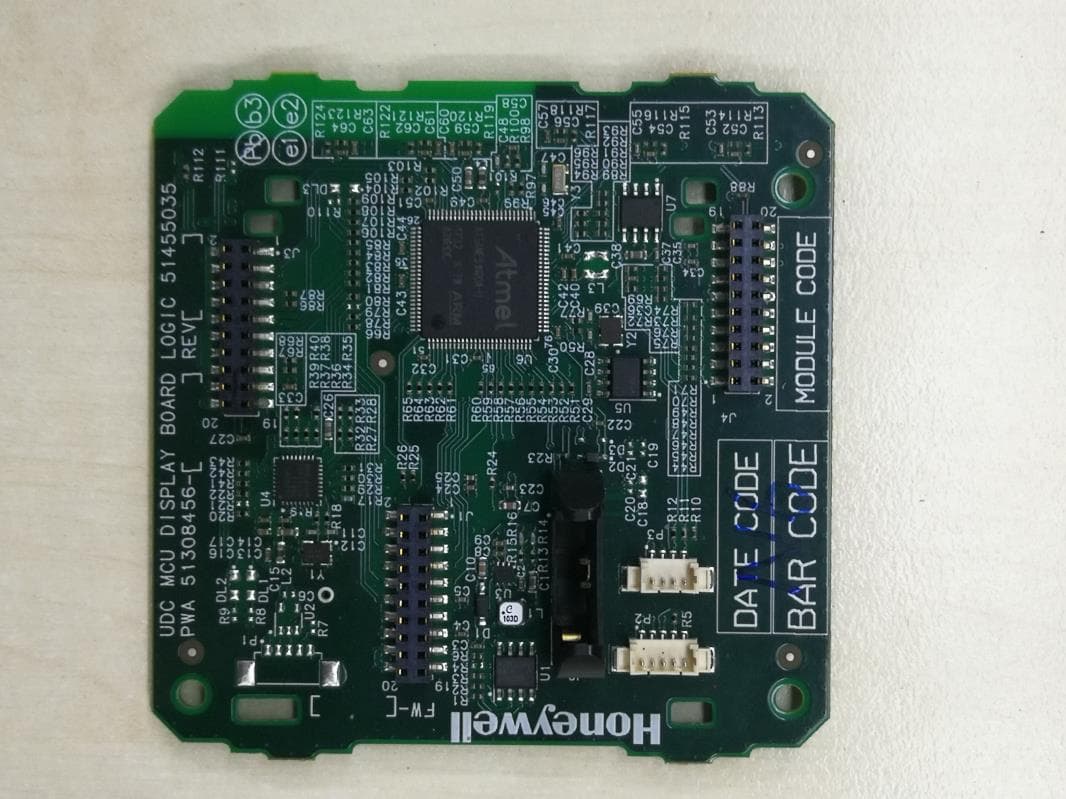
Click to zoom
Application Details
- Equipment Class
- DXX - Part 15 Low Power Communication Device Transmitter
- Date of Grant
- Jan 20, 2020
- Application Purpose
- Original Equipment
- Date of Application
- Jan 17, 2020
- Equipment Note
- BLE Module
- Frequency Range
- 2402.00000000 - 2480.00000000
- Country
- China
Documents & Files
Document Text
Text extracted from the exhibit documents filed with the FCC. Open a document above to read the original.
Users Manual
User manual Caution: This device complies with Part 15 of the FCC Rules / Innovation, Science and Economic Development Canada’s licence-exempt RSS(s). Operation is subject to the following two conditions: 1. this device may not cause harmful interference. 2. this device must accept any interference received, including interference that may cause undesired operation. L’émetteur/récepteur exempt de licence contenu dans le présent appareil est conforme aux CNR d’Innovation, Sciences et Développement économique Canada applicables aux appareils radio exempts de licence. L’exploitation est autorisée aux deux conditions suivantes : 1. L’appareil ne doit pas produire de brouillage; 2. L’appareil doit accepter tout brouillage radioélectrique subi, même si le brouillage est susceptible d’en compromettre le fonctionnement. Changes or modifications not expressly approved by the party responsible for compliance could void the user's authority to operate the equipment. This equipment has been tested and found to comply with the limits for a Class B digital device, pursuant to part 15 of the FCC Rules. These limits are designed to provide reasonable protection against harmful interference in a residential installation. This equipment generates uses and can radiate radio frequency energy and, if not installed and used in accordance with the instructions, may cause harmful interference to radio communications. However, there is no guarantee that interference will not occur in a particular installation. If this equipment does cause harmful interference to radio or television reception, which can be determined by turning the equipment off and on, the user is encouraged to try to correct the interference by one or more of the following measures: —Reorient or relocate the receiving antenna. —Increase the separation between the equipment and receiver. —Connect the equipment into an outlet on a circuit different from that to which the receiver is connected. —Consult the dealer or an experienced radio/TV technician for help. Under Industry Canada regulations, this radio transmitter may only operate using an antenna of a type and maximum (or lesser) gain approved for the transmitter by Industry Canada. To reduce potential radio interference to other users, the antenna type and its gain should be so chosen that the equivalent isotropically radiated power (e.i.r.p.) is not more than that necessary for successful communication. Conformément à la réglementation d'Industrie Canada, le présent émetteur radio peut fonctionner avec une antenne d'un type et d'un gain maximal (ou inférieur) approuvé 2 pour l'émetteur par Industrie Canada. Dans le but de réduire les risques de brouillage radioélectrique à l'intention des autres utilisateurs, il faut choisir le type d'antenne et son gain de sorte que la puissance isotrope rayonnée équivalente (p.i.r.e.) ne dépasse pas l'intensité nécessaire à l'établissement d'une communication satisfaisante. Information for the OEM Integrators This device is intended for OEM integrators only. Please see the full grant of equipment document for restrictions. Label Information to the End User by the OEM or Integrators If the FCC ID of this module is not visible when it is installed inside another device, then the outside of the device into which the module is installed must be label with “Contains FCC ID: 2AVFQ-MCUDISP and IC: 25762-MCUDISP The requirement for KDB 996369 D03: 1. List of applicable FCC rules FCC Part 15. 249. 2. Summarize the specific operational use conditions None 3. Limited module procedures The module is a single module, so this requirement is not applicable to the product. 4. Trace antenna designs The module uses the PCB antenna, so this requirement is not applicable to the product. 5. RF exposure considerations None 6. Antennas PCB antenna 7. Label and compliance information If this certified module is installed inside the host device, then the outside of the host must be labeled with “Contains FCC ID: 2AVFQ-MCUDISP and IC: 25762-MCUDISP”. 8. Information on test modes and additional testing requirements The host manufacturer can use the software of “prodtest.exe” to make the Bluetooth transmit continuously. 9. Additional testing, Part 15 Subpart B disclaimer The module only complies with the FCC Part 15.249. If the module is installed in the host device, the host manufacturer is responsible for the compliance to any other FCC rules that apply to the host not covered by the modular transmitter grant of certification. For example, if the host manufacturer markets their product as being Part 15 Subpart B compliant (when it also contains unintentional-radiator digital circuity), then the host manufacturer shall provide a notice stating that the final host product still requires Part 15 Subpart B compliance testing with the modular transmitter installed. 1.Introduction The MCU_Display module integrated with a MCU and Bluetooth module LBCA2HNZYZ-711. The MCU IC communicate with the Bluetooth module by SPI interface. The LBCA2HNZYZ-711 is a Bluetooth Low Energy Module 4.2 with internal PCB printing antenna. Please see LBCA2HNZYZ-711 spec for detail information. 2.Features ●Bluetooth standard:BLE4.2 ●Frequency range: 2400~2480MHz ●Receiver sensitivity (Ideal transmitter PER <= 30.8%): -93dBm(TYP), -70dBm(MAX) ●Maximum input signal level (PER <= 30.8%):-10dBm(MIN) ●Power supply: 3.3V ●RX MODE:5.1mA ,TX mode:4.8mA ●Low power consumption ●Operating Temperature range: 0°C~ +55°C ●RoHS Compliance 3. Applications ●Industrial Measurement and Control 4. Module Diagram 5. Operating Condition Parameter Min Typ Max Operate Temperature 0º 25 º 55º Transportation and Storage Temperature -40 º 66º Work Voltage 2.5V 3.3V 3.45V RF Load Impedance 50Ω SPI/Reset Power, 3.3V U6 ATSAME53N20A U8 LBCA2HNZYZ-711 BLE Module MCU MCU Y2 Crystal 12M 2402-2480MHz 6. RF Electronic Specification 7. Reflow Profile for BLE module The recommendation conditions of soldering are as in the following figure. When p…
Text truncated - open the document above for the full version.
Cover Letter(s)
Honeywell Integrated Technology (China) Co., Ltd 053019-02a Request for Modular/Limited Modular Approval Date: Jan 6, 2020 Subject: Manufacturer’s Declaration for ☒ - Modular Approval ☐ - Split Modular Approval ☐ - Limited Modular Approval ☐ - Limited Split Modular Approval Confidentiality Request for: 2AVFQ-MCUDISP 8 Basic Requirements – FCC Part 15.212(a)(1) For Items Marked “NO(*)”, the Limited Module Description Must be Filled Out on the Following Pages Modular Approval Requirement Requirement Met 1. The modular transmitter must have its own RF shielding. This is intended to ensure that the module does not have to rely upon the shielding provided by the device into which it is installed in order for all modular transmitter emissions to comply with FCC limits. It is also intended to prevent coupling between the RF circuitry of the module and any wires or circuits in the device into which the module is installed. Such coupling may result in non-compliant operation. The physical crystal and tuning capacitors may be located external to the shielded radio elements. 15.212(a)(1)(i) ☒ - YES ☐ - NO(*) Details:The module has a metal shield.Refer to the external photo of EUT. 2. The modular transmitter must have buffered modulation/data inputs (if such inputs are provided) to ensure that the module will comply with FCC requirements under conditions of excessive data rates or over-modulation. 15.212(a)(1)(ii) ☒ - YES ☐ - NO(*) Details: Data to the modulation circuit is buffered as described in the clause 4 of user manual provided with the application. 3. The modular transmitter must have its own power supply regulation on the module. This is intended to ensure that the module will comply with FCC requirements regardless of the design of the power supplying circuitry in the device into which the module is installed. 15.212(a)(1)(iii) ☒ - YES ☐ - NO(*) Details: The module contains its own power supply regulation integrated in the chip. Please refer to the clause 4 of user manual with this application. 4. The modular transmitter must comply with the antenna and transmission system requirements of §§ 15.203, 15.204(b), 15.204(c), 15.212(a), and 2.929(b). The antenna must either be permanently attached or employ a ‘‘unique’’ antenna coupler (at all connections between the module and the antenna, including the cable). The ‘‘professional installation’’ provision of § 15.203 is not applicable to modules but can apply to limited modular approvals under paragraph 15.212(b). 15.212(a)(1)(iv) ☒ - YES ☐ - NO(*) Details: The module uses PCB antenna. The antenna information can be found in user manual and operation description provided with the application. 5. The modular transmitter must be tested in a stand-alone configuration, i.e., the module must not be inside another device during testing. This is intended to demonstrate that the module is capable of complying with Part 15 emission limits regardless of the device into which it is eventually installed. Unless the transmitter module will be battery powered, it must comply with the AC line conducted requirements found in Section 15.207. AC or DC power lines and data input/output lines connected to the module must not contain ferrites, unless they will be marketed with the module (see Section 15.27(a)). The length of these lines shall be length typical of actual use or, if that length is unknown, at least 10 centimeters to insure that there is no coupling between the case of the module and supporting equipment. Any accessories, peripherals, or support equipment connected to the module during testing shall be unmodified or commercially available (see Section 15.31(i)). 15.212(a)(1)(v) ☒ - YES ☐ - NO(*) Details: The module was tested stand-alone as shown in test setup photographs filed with this application. Honeywell Integrated Technology (China) Co., Ltd 053019-02a Modular Approval Requirement Requirement Met 6. The modular transmitter must be labeled with its own FCC ID number, or use an electron display (see KDB Publication 784748). If using a permanently affixed label with its own FCC ID number, if the FCC ID is not visible when the module is installed inside another device, then the outside of the device into which the module is installed must also display a label referring to the enclosed module. This exterior label can use wording such as the following: “Contains Transmitter Module FCC ID: XYZMODEL1” or “Contains FCC ID: XYZMODEL1.” Any similar wording that expresses the same meaning may be used. The Grantee may either provide such a label, an example of which must be included in the application for equipment authorization, or, must provide adequate instructions along with the module which explain this requirement. In the latter case, a copy of these instructions must be included in the application for equipment authorization. If the modular transmitter uses an electronic display of the FCC identification number, the information must be readily accessible and visible on the modular transmitter or on the device in which it is installed. If the module is installed inside another device, then the outside of the device into which the module is installed must display a label referring to the enclosed module. This exterior label can use wording such as the following: “Contains FCC certified transmitter module(s).” Any similar wording that expresses the same meaning may be used. The user manual must include instructions on how to access the electronic display. A copy of these instructions must be included in the application for equipment authorization. 15.212(a)(1)(vi) ☒ - YES ☐ - NO(*) Details: The FCC ID is printed on the label of the module.Refer to the label of EUT. 7. The modular transmitter must comply with all specific rule or operating requirements applicable to the transmitter, including all the conditions provided in the integration instructions by the grantee. A copy of these instructions must be included in the application for equipment authoriza…
Text truncated - open the document above for the full version.
External Photos
FCC ID: 2AVFQ-MCUDISP IC: 25762-MCUDISP Page 1 of 1 External Picture
ID Label/Location Info
Label location
Internal Photos
FCC ID: 2AVFQ-MCUDISP IC: 25762-MCUDISP Page 1 of 3 Internal Picture FCC ID: 2AVFQ-MCUDISP IC: 25762-MCUDISP Page 2 of 3 FCC ID: 2AVFQ-MCUDISP IC: 25762-MCUDISP Page 3 of 3
RF Exposure Info
Honeywell Integrated Technology (China) Co., Ltd SAR COMPLIANCE REPORT Report Type: FCC SAR assessment report Model: MCUDISP REPORT NUMBER: 191200197SHA-002 ISSUE DATE: Jan 16, 2020 DOCUMENT CONTROL NUMBER: TTRFFCCSAR-01_V1 © 2018 Intertek Intertek Testing Services Shanghai Building No.86, 1198 Qinzhou Road (North) Caohejing Development Zone Shanghai 200233, China Telephone: 86 21 6127 8200 www.intertek.com TEST REPORT This report is for the exclusive use of Intertek's Client and is provided pursuant to the agreement between Intertek and its Client. Intertek's responsibility and liability are limited to the terms and conditions of the agreement. Intertek assumes no liability to any party, other than to the Client in accordance with the agreement, for any loss, expense or damage occasioned by the use of this report. Only the Client is authorized to permit copying or distribution of this report and then only in its entirety. Any use of the Intertek name or one of its marks for the sale or advertisement of the tested material, product or service must first be approved in writing by Intertek. The observations and test results in this report are relevant only to the sample tested. This report by itself does not imply that the material, product, or service is or has ever been under an Intertek certification program. TTRFFCCSAR-01_V1© 2018 Intertek Page 2 of 8 Report no.: 191200197SHA-002 Applicant : Honeywell Integrated Technology (China) Co., Ltd No.430, Libing Rd., Zhangjiang Hi-tech Park, Pudong New area,Shanghai,P.R.C Manufacturer : Honeywell Integrated Technology (China) Co., Ltd No.430, Libing Rd., Zhangjiang Hi-tech Park, Pudong New area,Shanghai,P.R.C FCC ID : 2AVFQ-MCUDISP SUMMARY: The equipment complies with the requirements according to the following standard(s) or Specification: KDB447498 D01 General RF Exposure Guidance v06 FCC Part2.1091, FCC Part2.1093 FCC Part1.1307(b) PREPARED BY: REVIEWED BY: Project Engineer Teddy Yin Reviewer Daniel Zhao Report No.: 191200197SHA-002 TEST REPORT TTRFFCCSAR-01_V1© 2018 Intertek Page 3 of 8 Revision History Report No. Version Description Issued Date 191200197SHA-002 Rev. 01 Initial issue of report Jan 16, 2020 Report No.: 191200197SHA-002 TEST REPORT TTRFFCCSAR-01_V1© 2018 Intertek Page 4 of 8 1 GENERAL INFORMATION 1.1 Description of Equipment Under Test (EUT) Product name: BLE Module Type/Model: MCUDISP Description of EUT: The EUT is a BLE Module. Rating: DC 3.3V Category of EUT: Class B EUT type: Table top Floor standing Software Version: / Hardware Version: / Sample received date: Dec 8, 2019 Date of test: Dec 8~20, 2019 1.2 Technical Specification Frequency Range: 2402-2480MHz Support Standards: Bluetooth LE 4.2 Type of Modulation: GFSK Channel Number: 40 Data Rate: 1Mbps Channel Separation: 2MHz Antenna Information: -0.6dBi, PCB antenna Report No.: 191200197SHA-002 TEST REPORT TTRFFCCSAR-01_V1© 2018 Intertek Page 5 of 8 1.3 Description of Test Facility Name: Intertek Testing Services Shanghai Address: Building 86, No. 1198 Qinzhou Road(North), Shanghai 200233, P.R. China Telephone: 86 21 61278200 Telefax: 86 21 54262353 The test facility is recognized, certified, or accredited by these organizations: CNAS Accreditation Lab Registration No. CNAS L0139 FCC Accredited Lab Designation Number: CN1175 IC Registration Lab CAB identifier.: CN0051 VCCI Registration Lab Registration No.: R-14243, G-10845, C-14723, T-12252 A2LA Accreditation Lab Certificate Number: 3309.02 Report No.: 191200197SHA-002 TEST REPORT TTRFFCCSAR-01_V1© 2018 Intertek Page 6 of 8 2 SAR Assessment Test result: Pass 2.1 SAR Test Exclusion Limit 100 MHz – 6 GHz and ≤ 50 mm Report No.: 191200197SHA-002 TEST REPORT TTRFFCCSAR-01_V1© 2018 Intertek Page 7 of 8 100 MHz – 6 GHz and > 50 mm < 100 MHz and < 200 mm Report No.: 191200197SHA-002 TEST REPORT TTRFFCCSAR-01_V1© 2018 Intertek Page 8 of 8 2.2 Assessment Results The highest AV EIRP adjusted with tune-up tolerance is 81.0-95.3= -14.3dBm = 0.037mW < 10mW (Test Exclusion Thresholds of 2450MHz at 5mm). Therefore, the SAR requirement is deemed to be satisfied without test. ******************************************* END ************************************
Test Report
Honeywell Integrated Technology (China) Co., Ltd RF TEST REPORT Report Type: FCC Part 15.249 & ISED RSS-210 RF report Model: MCUDISP REPORT NUMBER: 191200197SHA-001 ISSUE DATE: Jan 16, 2020 DOCUMENT CONTROL NUMBER: TTRF15.249_V1 © 2018 Intertek Intertek Testing Services Shanghai Building No.86, 1198 Qinzhou Road (North) Caohejing Development Zone Shanghai 200233, China Telephone: 86 21 6127 8200 www.intertek.com TEST REPORT This report is for the exclusive use of Intertek's Client and is provided pursuant to the agreement between Intertek and its Client. Intertek's responsibility and liability are limited to the terms and conditions of the agreement. Intertek assumes no liability to any party, other than to the Client in accordance with the agreement, for any loss, expense or damage occasioned by the use of this report. Only the Client is authorized to permit copying or distribution of this report and then only in its entirety. Any use of the Intertek name or one of its marks for the sale or advertisement of the tested material, product or service must first be approved in writing by Intertek. The observations and test results in this report are relevant only to the sample tested. This report by itself does not imply that the material, product, or service is or has ever been under an Intertek certification program. TTRF15.249_V1 © 2018 Intertek Page 2 of 25 Report no.: 191200197SHA-001 Applicant: Honeywell Integrated Technology (China) Co., Ltd No.430, Libing Rd., Zhangjiang Hi-tech Park, Pudong New area,Shanghai,P.R.C Manufacturer: Honeywell Integrated Technology (China) Co., Ltd No.430, Libing Rd., Zhangjiang Hi-tech Park, Pudong New area,Shanghai,P.R.C FCC ID: 2AVFQ-MCUDISP IC: 25762-MCUDISP SUMMARY: The equipment complies with the requirements according to the following standard(s) or Specification: 47CFR Part 15 (2018): Radio Frequency Devices (Subpart C) ANSI C63.10 (2013): American National Standard of Procedures for Compliance Testing of Unlicensed Wireless Devices RSS-210 Issue 10 (December 2019): Licence-exempt Radio Apparatus (All Frequency Bands): Category I Equipment RSS-Gen Issue 5 (April 2018): General Requirements for Compliance of Radio Apparatus PREPARED BY: REVIEWED BY: Project Engineer Teddy Yin Reviewer Daniel Zhao Report No.: 191200197SHA-001 TEST REPORT TTRF15.249_V1 © 2018 Intertek Page 3 of 25 Content REVISION HISTORY................................................................................................................................................ 4 MEASUREMENT RESULT SUMMARY...................................................................................................................... 5 1 GENERAL INFORMATION ............................................................................................................................. 6 1.1 DESCRIPTION OF EQUIPMENT UNDER TEST (EUT) ..................................................................................................... 6 1.2 TECHNICAL SPECIFICATION .................................................................................................................................... 6 1.3 DESCRIPTION OF TEST FACILITY .............................................................................................................................. 7 2 TEST SPECIFICATIONS ................................................................................................................................... 8 2.1 STANDARDS OR SPECIFICATION ............................................................................................................................... 8 2.2 MODE OF OPERATION DURING THE TEST ................................................................................................................... 8 2.3 TEST SOFTWARE LIST ............................................................................................................................................ 9 2.4 TEST PERIPHERALS LIST ......................................................................................................................................... 9 2.5 TEST ENVIRONMENT CONDITION: ............................................................................................................................ 9 2.6 INSTRUMENT LIST .............................................................................................................................................. 10 2.7 MEASUREMENT UNCERTAINTY ............................................................................................................................. 11 3 RADIATED EMISSION ................................................................................................................................. 12 3.1 LIMIT .............................................................................................................................................................. 12 3.2 MEASUREMENT PROCEDURE ............................................................................................................................... 12 3.3 TEST CONFIGURATION ........................................................................................................................................ 14 3.4 TEST RESULTS OF RADIATED EMISSIONS ................................................................................................................. 16 4 POWER LINE CONDUCTED EMISSION ......................................................................................................... 19 4.1 LIMIT .............................................................................................................................................................. 19 4.2 TEST CONFIGURATION ........................................................................................................................................ 19 4.3 MEASUREMENT PROCEDURE ...........................................................................................................…
Text truncated - open the document above for the full version.
Test Setup Photos
FCC ID: 2AVFQ-MCUDISP IC: 25762-MCUDISP Page 1 of 2 Test Setup FCC ID: 2AVFQ-MCUDISP IC: 25762-MCUDISP Page 2 of 2 1. Radiated Emission Above 1GHz Below 1GHz
Contact Information
Applicant
Joy zhu
Technical Contact
Intertek Testing Services Limited ShanghaiTeddy Yin
[email protected]86-21-61215198
Building No.86, 1198 Qinzhou Road(North) · Shanghai · China
Test Firm
Intertek Testing Services ShanghaiLeah Xu
[email protected]+86 21 61278200
Technical Specifications
| # | Rule Parts | Frequency Range | Power Output |
|---|---|---|---|
| 1 | 15C | 2.40 GHz - 2.48 GHz | 37.00 µW |