2AVGPJLT733ACitizens Band Category B Device
J Plus, Inc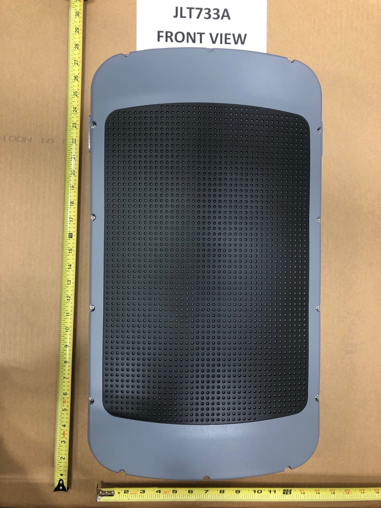
Click to zoom
Application Details
- Equipment Class
- CBD - Citizens Band Category A and B Devices
- Date of Grant
- Jun 08, 2020
- Application Purpose
- Original Equipment
- Date of Application
- Jun 08, 2020
- Equipment Note
- Citizens Band Category B Device
- Frequency Range
- 3560.00000000 - 3690.00000000
- Company
- J Plus, Inc
- Country
- United States
Documents & Files
Document Text
Text extracted from the exhibit documents filed with the FCC. Open a document above to read the original.
Users Manual
J Plus, Inc JLT733A User Manual Copyright©2019 J Plus, Inc The information contained herein is the property of J Plus and is provided without liability of errors, omissions, and mistakes. No part maybe reproduced or copied without written permission or contract. J Plus, Inc Revision History J Plus, Inc Contents 1 Introduction .................................................................................................................................................8 1.1 Overview ............................................................................................................................................. 8 1.2 Type of Small Cell ................................................................................................................................ 8 1.3 Benefits ............................................................................................................................................... 8 1.4 Network Block Diagram ........................................................................................................................ 9 2 System Features ...................................................................................................................................... 10 2.1 JLT733A System Main Functions ......................................................................................................10 2.1.1 3GPP Standards ................................................................................................................................10 2.2 JLT733A System Specifications .........................................................................................................12 2.3 JLT733A Main Functions ...................................................................................................................12 2.4 Equipment Specifications ...................................................................................................................14 2.5 Environmental Specifications .............................................................................................................14 2.6 RF Specifications ...............................................................................................................................15 2.6.1 Downlink transmission (for 20MHz BW) .............................................................................................15 2.6.2 Uplink Reception (for 20MHz BW) .....................................................................................................15 2.7 RF Block Description ..........................................................................................................................16 2.8 Digital block Description .....................................................................................................................17 2.9 Software block Description .................................................................................................................18 2.9.1 LTE protocol Stack .............................................................................................................................19 2.9.2 Security .............................................................................................................................................20 2.9.3 Management ......................................................................................................................................20 3 Interface and LED Description ................................................................................................................. 21 3.1 Interface and Connector .....................................................................................................................21 3.2 LED....................................................................................................................................................22 4 Initial Connection ...................................................................................................................................... 23 4.1 Cable Connection ...............................................................................................................................23 4.2 Connection Test .................................................................................................................................24 5 Connection via Web GUI .......................................................................................................................... 24 6 Web GUI Operation .................................................................................................................................. 26 6.1 Web GUI Menu ...................................................................................................................................26 6.2 Configuration Menu ............................................................................................................................31 6.2.1 General Menu .....................................................................................................................................31 6.2.1.1 Network Interface ...............................................................................................................................31 6.2.1.2 Network Function ...............................................................................................................................34 6.2.1.3 Security Gateway ...............................................................................................................................34 6.2.1.4 DHCP Server ......................................................................................................................................35 6.2.1.5 CWMP ...............................................................................................................................................35 6.2.1.6 Clock sync & SYS time settings ...................................…
Text truncated - open the document above for the full version.
Users Manual
J Plus, Inc 6.2.3.4 MR From the tree menu, you can select MR to move on to the measurement report setup page. Choose one of trigger quantities (RSRP, RSRQ, RSCP, Ec/No) from the list. Insert threshold value and click the Save button as shown in Figure 36 below. Please refer to Table 13 below for the detailed input parameter information. * All units are defined reported value from TS36133 (RSRP: 9.1.4, RSRQ: 9.1.7), TS25133 (RSCP: 9.1.1.3, Ec/No: 9.1.2.3). Menu Description Intra-frequencySelect the Event A3 or A4. If you select event A3, then A3 is supported. (Event EUTRAN HOA4 is the same as A3.) Inter-RATSelect the Event B1 or B2. If you select event B1 then B1 is supported. (Event B2 HO/Redirect/SRVCCis the same as B1.) A1, A3, A4 Select the type of trigger quantities for each event. Select the type of trigger quantities for each event. A2There are 4 options in A2 Event. Inter-freq Ho, Inter-RAT HO/REDIR, SRVCC, Blind Redirection. If you don't want to use event, then insert 0 in threshold value. RSRP, range: [0, 97] Insert RSRP threshold for each event. RSRQ, range: [0, 34] Insert RSRQ threshold for each event. Intra-Freq HO/ANR Insert Intra-Freq HO/ANR offset value. range: [-30, 30] A5 A5(Inter-Freq Ho, Inter-Freq ANR) threshold range is RSRP/Q1 - RSRP/Q2. B1 ( UTRA ) Select the type of trigger quantity to each event. B2 ( UTRA / GERAN ) RSCP, range: [-5, 91] Insert a RSCP threshold values for each event. Ec/No, range: [0, 63] Insert an Ec/No threshold values for each event. RSSI, range: [0, 63] Insert threshold value to each event (B1, B2). Table 13: Description of MR parameter J Plus, Inc Figure 36: A1 - A5, B1, B2 MR Setup menu J Plus, Inc 6.2.3.5 Neighbor Cell From the tree menu, select Neighbor Cell to move onto the Neighbor Cell setup page. You can Add Neighbor Cell and modify/delete a registered neighbor cell. Please refer to Table 14 for detailed input parameter information. Like other setting procedure, the changes must be saved. Menu Description eNodeB Type Select the type of Neighbor Cell. IP Address Insert IP address of Neighbor Cell for X2 HO. Cell ID Insert eNodeB ID of Neighbor Cell. PLMN ID Insert PLMN ID of the Neighbor Cell. TAC Insert TAC of the Neighbor Cell. PCI Insert PCI of the Neighbor Cell. Insert DL EARFCN of Neighbor Cell. DL EARFCNThis must be the frequency value included within EUTRA Frequency under basic menu. Insert UL EARFCN of Neighbor Cell. UL EARFCNThis must be the frequency value included within EUTRA Frequency under basic menu. q-OffsetCell Insert q-OFFSET of the Neighbor Cell. Select X2 setup is enabled or disabled for the neighbor cell. X2 TriggerIf X2 Trigger is disabled, S1AP based hand-out triggered. If X2 Trigger is enabled, X2 based hand-out triggered. Access Mode Select the type of Access Mode. CSG ID Insert CSG ID of the Neighbor Cell Table 14: Description of Neighbor Cell Parameter J Plus, Inc Figure 37: Neighbor Cell configuration page Figure 38: Neighbor Cell Add Confirmation Window J Plus, Inc Figure 39: Registered Neighbor Cell Information Figure 40: Neighbor Cell Modify Confirmation Window J Plus, Inc Figure 41: Neighbor Cell Delete Confirmation Window J Plus, Inc 6.2.3.6 UTRA Frequency From the tree menu, select UTRA Frequency to move onto the UTRA Frequency setup page. You can add a UTRA Frequency and modify/delete a registered UTRA Frequency. If inter-RAT Handover to UTRA Frequency is required, please choose Handover in Mobility to UTRA. Please refer to Table 15 for detailed input parameter information. Menu Description Mobility to UTRA UTRA FDD /TDD Select Handover or Redirection for UTRAN. UTRA Frequency Form Duplex Select type of duplex. Band Indicator Case of TDD, Band indicator is enabled (Band A - Band F). Thresh X High Insert Thresh X High of UTRA Frequency. Thresh X Low Insert Thresh X Low of UTRA Frequency. Offset Frequency Insert Offset Frequency of UTRA Frequency. CSFB Select CSFB enable or disable. Cell Reselection Priority Insert Cell Reselection Priority of UTRA Frequency. DL ARFCN Insert DL ARFCN of UTRA Frequency. UL ARFCN Insert UL ARFCN of UTRA Frequency. Qrxlevmin Insert Qrxlevmin of UTRA Frequency. Pmax UTRA Insert Pmax UTRA of UTRA Frequency. QqualMin Insert QqualMin of UTRA Frequency. Table 15: Description of UTRA Frequency Parameter J Plus, Inc Figure 42: Mobility to UTRA setup on UTRA Frequecny menu Figure 43: Mobility to UTRA save confirmation on UTRA Frequency menu J Plus, Inc Figure 44: Add UTRA Frequency and Confirmation Figure 45: New UTRA Frequency Registered J Plus, Inc Figure 46: Modify Registered UTRA Frequency and Confirmation Window Figure 47: Delete registered UTRA Frequency and Confirmation J Plus, Inc Figure 48: Result of registered UTRA Frequency deletion J Plus, Inc 6.2.3.7 UTRA Neighbor Cell From the tree menu, select UTRA Neighbor Cell to move onto the UTRA Neighbor Cell setup page. You can Add UTRA Neighbor Cell and modify/delete a registered UTRA Neighbor Cell. If inter-RAT Handover to UTRA Neighbor Cell is required, please choose Handover in Mobility to UTRA. Please refer to Table 16 for detailed input parameter information Menu Description Mobility to UTRA UTRA FDD / TDD Select Handover or Redirection for UTRAN. UTRA Neighbor Cell Form RNC ID Insert RNC ID of UTRA Neighbor cell. CELL ID Insert CELL ID of UTRA Neighbor cell. IP Address Insert IP Address of UTRA Neighbor cell. PLMN ID Insert PLMN ID of UTRA Neighbor cell. Insert DL ARFCN of UTRA Neighbor cell. DL ARFCN(This must be the frequency value included within UTRA Frequency under UTRA Frequency menu) Insert UL ARFCN of UTRA Neighbor cell. UL ARFCN(This must be the frequency value included within UTRA Frequency under UTRA Frequency menu) LAC Insert LAC of UTRA Neighbor cell. RAC Insert RAC of UTRA Neighbor cell. URA Insert URA of UTRA Neighbor cell. PCS Insert PCS of UTRA Neighbor cell. Pcpich Tx Power Insert Pcpich Tx Power of UTRA Neighbor cell. Duplex Select type of duplex. Ccpch Tx Power Insert Ccpch Tx Power of UTRA Neighbor …
Text truncated - open the document above for the full version.
ID Label/Location Info
Product Category B CBSD Model: JLT733A Date: 2018.10 S/N: xxxxxxxxxxxxxx MAC: yyyyyyyyyyyyyy AC: ~100-240V;50-60Hz CurrentRating: 2A MADE IN KOREA J Plus, Inc FCC ID:2AVGPJLT733A
Internal Photos
J Plus, Inc 1. PCB Bottom It consists of LTE MODEM, DDR, Flash memory and power circuit. Power LTE MODEM DDR DDR Flash memory J Plus, Inc 2. PCB Top It consists of RF, GPS, Ethernet, FPGA, L2 Switch, etc. RF Block RF Block FPGA FPGA GPS Block External Port RF Port x 4EA J Plus, Inc 3. HPA (High Power Amplifier) Module HPA amplifies the DL signal and sends it to the antenna, and on the contrary, amplifies the UL signal and sends it to the RF Block. J Plus, Inc HPA top bottom HPA Top Side 733 Amplifier Side J Plus, Inc 4. Front Side Open the top cover of the device, you will find PCB, HPA, BPF, PSU. Antenna structure: PCB PCB PSU BPF HPA RF Port x 4EA GPS Port J Plus, Inc 6. BPF (Band Pass Filter) Reduces unwanted signals other than the desired signal. J Plus, Inc 7. GPS Antenna
Parts List/Tune Up Info
J Plus, Inc JLT733A Turn-up Procedure Turn-up Procedure 1. If using a PC for management, Connect cable from the Control PC to the local MGMT Port on the Small Cell and set the IP address. a. If using a router for management, Connect cable from the Small Cell WAN Port to the router and access the Small Cell through the router from WAN IP. 2. Turn on the power to the Small Cell and wait for the boot-up. Confirm you can make a connection from the local MGMT Port or WAN Port. 3. From the GUI Menu turn the RF module on or off. Configuration→LTE → RF • The green UN-BLOCK status indicates the RF is turned on and confirms the Small Cell has a S1 connection. • To change the TX Power, insert the number of value (dBm) and click the Apply button. The TX power will be changed. End of Procedure
RF Exposure Info
Prediction of MPE limit at a given distance Equation from page 18 of OET Bulletin 65, Edition 97-01 where:S = power density P = power input to the antenna G = power gain of the antenna in the direction of interest relative to an isotropic radiator R = distance to the center of radiation of the antenna Using absolute worst case Port 0,1,2,3 Maximum peak output power at device output terminal:29.99dBm Cable and Jumper loss:0dB Maximum peak output power at antenna input terminal:29.99dBm 997.7000638mW Single Antenna gain (typical):14dBi Number of Antennae:4 Total Antenna gain (typical):20dBi 100(numeric) Prediction distance:90cm Prediction frequency:3690MHz MPE limit for uncontrolled exposure at prediction frequency:1 mW/cm 2 Power density at prediction frequency:0.980178376 mW/cm 2 9.801783758 W/m 2 Tx On time:1ms Tx period time:1ms Average Factor:100% Average Power density at prediction frequency:9.801783758 W/m 2 0.980<1.0 2 4R PG S = ONE WORLDOURAPPROVAL
Test Report
Nemko USA Inc., a testing laboratory, is accredited by NVLAP. The tests included in this report are within the scope of this accreditation. www.nemko.com ONE WORLDOURAPPROVAL Test report 364246-TRFWL Date of issue: January 25, 2019 Applicant: J Plus, Inc Product: CBDS Cat-B High Power Outdoor Small Cell Model: JLT – 733A (CBRS) FCC ID: 2AVGPJLT733A Specifications: FCC 47 CFR Part 96 Citizens Broadband Radio Service Report reference ID: 364246-TRFWL Page 2 of 67 Lab and test locations Company name Nemko USA Inc. Address 2210 Faraday Ave, Suite 150 City Carlsbad State California Postal code 92008 Country USA Telephone +1 760 444 3500 Website www.nemko.com FCC Site Number Test Firm Registration Number: 392943 Designation Number: US5058 ISED Test Site 2040B-3 Tested by Martha Espinoza,Wireless Engineer Reviewed by Chip Fleury, WL & Certification Supervisor Review date February 1, 2019 Reviewer signature Limits of responsibility Note that the results contained in this report relate only to the items tested and were obtained in the period between the date of initial receipt of samples and the date of issue of the report. This test report has been completed in accordance with the requirements of ISO/IEC 17025. All results contain in this report are within Nemko USA’s ISO/IEC 17025 accreditation. Copyright notification Nemko USA Inc. authorizes the applicant to reproduce this report provided it is reproduced in its entirety and for use by the company’s employees only. Any use which a third party makes of this report, or any reliance on or decisions to be made based on it, are the responsibility of such third parties. Nemko USA Inc. accepts no responsibility for damages, if any, suffered by any third party as a result of decisions made or actions based on this report. © Nemko USA Inc. Report reference ID: 364246-TRFWL Page 3 of 67 Table of contents Table of contents .......................................................................................................................................................................................................... 3 Section 1. Report summary ................................................................................................................................................................................. 4 1.1 Applicant and manufacturer ................................................................................................................................................................................................ 4 1.2 Test specifications ................................................................................................................................................................................................................. 4 1.3 Test method .......................................................................................................................................................................................................................... 4 1.4 Statement of compliance ..................................................................................................................................................................................................... 4 1.5 Exclusions .............................................................................................................................................................................................................................. 4 1.6 Test report revision history .................................................................................................................................................................................................. 4 Section 2. Summary of test results ....................................................................................................................................................................... 5 2.1 FCC Part 96 test results ......................................................................................................................................................................................................... 5 Section 3. Equipment under test (EUT) details ..................................................................................................................................................... 6 3.1 Sample information .............................................................................................................................................................................................................. 6 3.2 EUT information .................................................................................................................................................................................................................... 6 3.3 Technical information ........................................................................................................................................................................................................... 6 3.4 Product description and theory of operation ..................................................................................................................................................................... 7 3.5 EUT exercise details .............................................................................................................................................................................................................. 7 3.6 EUT setup diagram ................................................................................................................................................................................................................ 8 3.6 EUT setup diagram, continued ............................................................................................................................................................................................. 8 3.7 EUT sub assemblies ..................................…
Text truncated - open the document above for the full version.
Test Report
Section 8 Testing data Test name FCC 96.41(e)(1) 3.5 GHz emissions and interference limits Specification FCC Part 96 Report reference ID: 364246-TRFWL Page 31 of 67 8.4 FCC 96.41(e)(1) 3.5 GHz emissions and interference limits 8.4.1 Definitions and limits General protection levels. Except as otherwise specified in paragraph (e)(2) of this section, for channel and frequency assignments made by the SAS to CBSDs, the conducted power of any emission outside the fundamental emission (whether in or outside of the authorized band) shall not exceed −13 dBm/MHz within 0–10 MHz above the upper SAS-assigned channel edge and within 0–10 MHz below the lower SAS-assigned channel edge. At all frequencies greater than 10 MHz above the upper SAS assigned channel edge and less than 10 MHz below the lower SAS assigned channel edge, the conducted power of any emission shall not exceed −25 dBm/MHz. The upper and lower SAS assigned channel edges are the upper and lower limits of any channel assigned to a CBSD by an SAS, or in the case of multiple contiguous channels, the upper and lower limits of the combined contiguous channels. (3) Measurement procedure. (i) Compliance with this provision is based on the use of measurement instrumentation employing a resolution bandwidth of 1 MHz or greater. However, in the 1 MHz bands immediately outside and adjacent to the licensee's authorized frequency channel, a resolution bandwidth of no less than one percent of the fundamental emission bandwidth may be employed. A narrower resolution bandwidth is permitted in all cases to improve measurement accuracy provided the measured power is integrated over the full reference bandwidth (i.e., 1 MHz or 1 percent of emission bandwidth, as specified). The emission bandwidth is defined as the width of the signal between two points, one below the carrier center frequency and one above the carrier center frequency, outside of which all emissions are attenuated at least 26 dB below the transmitter power. 8.4.2 Test summary Verdict Pass Test date December 4, 2018 Temperature 23 °C Test engineer Martha Espinoza, EMC & Wireless Test Engineer Air pressure 1005 mbar Test location Wireless Bench Relative humidity 32 % Test summary Note: For 10MHz Emissions mask – the closest emission to the limit is -7.29dB from High Channel 16QAM plot below. Therefore since this is a conducted limit and the emissions at the antenna port would be from Ports 0 and 1 an additional worst case 3dB has to be added to the result. Therefore the EUT emissions mask worst case emission is 4.29dB under the limit. (Ports 2 and 3 are identical uncorrelcated outputs) For 20MHz Emissions mask – the closest emission to the limit is -6.36dB from High Channel QPSK plot below. Therefore since this is a conducted limit and the emissions at the antenna port would be from Ports 0 and 1 an additional worst case 3dB has to be added to the result. Therefore the EUT emissions mask worst case emission is 3.36dB under the limit. (Ports 2 and 3 are identical uncorrelcated outputs) Section 8 Testing data Test name FCC 96.41(e)(1) 3.5 GHz emissions and interference limits Specification FCC Part 96 Report reference ID: 364246-TRFWL Page 32 of 67 8.4.3 Observations, settings and special notes Spectrum analyser settings for measurements within 1 MHz from the SAS assigned channel edges: Resolution bandwidth 100 kHz Video bandwidth 300 kHz Detector mode RMS Trace mode Power averaging Power integration Over 100 kHz for 10 MHz channel; Over 200 kHz for 20 MHz channel Spectrum analyser settings for measurements outside 1 MHz from the SAS assigned channel edges: Resolution bandwidth 1 MHz Video bandwidth 3 MHz Detector mode RMS Trace mode Power averaging OFFSET Calculaton: For 10MHz Spurious and emission mask offset is 38.2 dB. 38.2dB = 30.2dB (Attenuator) + 8dB (cable loss) 20 MHz Spurious and emission mask plots offset is 11.01. 11.01 = 10dB (Attenuator) = 1.01dB (cable loss) The correction factor was applied properly in each case, for compensated the loss caused by the attenuator and the cables losses. Note: The EUT has 4 identical ports with four identical configurations. Port 0 was determined to represent worse case and is displayed below to demonstrate compliance to the FCC 96.41(e)(1) 3.5 GHz emissions and interference limits. Ports 1 ,2 and 3 data measurement results are available if required. Section 8 Testing data Test name FCC 96.41(e)(1) 3.5 GHz emissions and interference limits Specification FCC Part 96 Report reference ID: 364246-TRFWL Page 33 of 67 8.4.4 Test data Table 8.4-1 Emission mask measurements for 10 MHz channel Port 0, Low, Mid and High Channel Figure 8.4-1: Emission mask measurements plot port 0, Low channel (3555 MHz), 16QAM Figure 8.4-2: Emission mask measurements plot port 0, Low channel (3555 MHz), 64QAM Figure 8.4-3: Emission mask measurements plot port 0, Low channel (3555 Hz), QPSK Figure 8.4-4: Emission mask measurements plot port 0, Mid channel (3625 MHz), 16QAM Section 8 Testing data Test name FCC 96.41(e)(1) 3.5 GHz emissions and interference limits Specification FCC Part 96 Report reference ID: 364246-TRFWL Page 34 of 67 8.4.4 Test data Tables 8.4-2: Emission mask measurements for 10 MHz channel Port 0, Low, Mid and High Channel Figure 8.4-5: Emission mask measurements plot port 0, Mid channel (3625 MHz), 64QAM Figure 8.4-6: Emission mask measurements plot port 0, Mid channel (3555 MHz), QPSK Figure 8.4-7: Emission mask measurements plot port 0, High channel (3695 MHz), 16QAM Figure 8.4-8: Emission mask measurements plot port 0, High channel (3695 MHz), 64QAM Section 8 Testing data Test name FCC 96.41(e)(1) 3.5 GHz emissions and interference limits Specification FCC Part 96 Report reference ID: 364246-TRFWL Page 35 of 67 8.4.4 Test data Table 8.4-3: Emission mask measurements for 10 MHz channel Port 0, Showing worst case High Channel Figure 8.4-9: Emission mask measurements plot port 0, High channel (3695 MHz), QPSK Section 8 Testing data Test name FCC 96.41(…
Text truncated - open the document above for the full version.
Test Report
www.nemko.com Nemko San Diego, a testing laboratory, is a authorized test lab (ATL) by the CBRS Alliance for standard WINNF-TS-0122 WINNF.docx; Date: Dec 2018 ONE WORLD OUR APPROVAL Wireless test report – 390910-2TRFWL Applicant: J Plus, Inc. Product name: CBSD Cat-B High Power Outdoor Small Cell Model: Model variant: JLT733A N/A FCC ID: 2AVGPJLT733A Specifications: WINNF-TS-0122, Version V1.0.0 Test and Certification for Citizens Broadband Radio Service (CBRS); Conformance and Performance Test Technical Specification; CBSD/DP as Unit Under Test (UUT) WINNF-IN-00129, Version V1.0.0.0 WInnForum CBSD/DP UUT Security Test 6 Cases Tutorial Date of issue: February 6, 2020 Test engineer(s): Tom Tidwell, Wireless/EMC Specialist Signature: Reviewed by: Juan M. Gonzalez/Business Dev. Manager Signature: Report reference ID: 390910-2TRFWL(CBRS_WINNF-TS-0122_SAS) Page 2 of 221 Test location(s) Company name Nemko USA Inc. Address 2210 Faraday Ave, Suite 150 City Carlsbad State California Postal code 92008 Country USA Telephone +1 760 444 3500 Website www.nemko.com FCC Site Number Test Firm Registration Number: 392943 Designation Number: US5058 ISED Test Site 2040B-3 Limits of responsibility Note that the results contained in this report relate only to the items tested and were obtained in the period between the date of initial receipt of samples and the date of issue of the report. This test report has been completed in accordance with the requirements of WINNF-TS-0122 [Test and Certification for Citizens Broadband Radio Service (CBRS); Conformance and Performance Test Technical Specification; CBSD/DP as Unit Under Test (UUT)] . Nemko San Diego has successfully completed the requirements to become a WInnForum CBRS Approved Lab and a CBRS Alliance Authorized Test Lab: https://cbrs.wirelessinnovation.org/cbsd-certification-program . Copyright notification Nemko USA Inc. authorizes the applicant to reproduce this report provided it is reproduced in its entirety and for use by the company’s employees only. Any use which a third party makes of this report, or any reliance on or decisions to be made based on it, are the responsibility of such third parties. Nemko USA Inc. accepts no responsibility for damages, if any, suffered by any third party as a result of decisions made or actions based on this report. © Nemko USA Inc. Report reference ID: 390910-2TRFWL(CBRS_WINNF-TS-0122_SAS) Page 3 of 221 Table of contents Table of contents .......................................................................................................................................................................................................... 3 Section 1. Report summary ................................................................................................................................................................................. 5 1.1 Applicant and manufacturer ................................................................................................................................................................................................ 5 1.2 Test specifications ............................................................................................................................................................…
Text truncated - open the document above for the full version.
Contact Information
Applicant
Daniel Hur
Test Firm
Nemko USA, Inc. - San Diego EMC DivisionJan Blomgren
[email protected]760-444-3500
Technical Specifications
| # | Rule Parts | Frequency Range | Power Output | Emission | Tolerance |
|---|---|---|---|---|---|
| 4 | 96 | 3.56 GHz - 3.69 GHz | 50 W | 17M9W7D | 16.3 ppm |