2AVMS-406012502000, 406000
OrthAlign Inc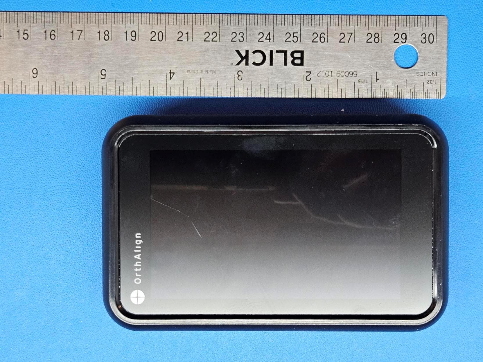
Click to zoom
Application Details
- Equipment Class
- DTS - Digital Transmission System
- Date of Grant
- Jul 09, 2026
- Application Purpose
- Original Equipment
- Equipment Note
- 502000, 406000
- Frequency Range
- 2402.00000000 - 2480.00000000
- Company
- OrthAlign Inc
- Country
- United States
Documents & Files
Document Text
Text extracted from the exhibit documents filed with the FCC. Open a document above to read the original.
Users Manual
Lantern ® Hip Instructions for Use: 001542-US Rev BA (06/2026) Page 1 of 6 LANTERN ® HIP INSTRUCTIONS FOR USE OrthAlign, Inc. 153 Technology Irvine, CA, 92618 USA www.orthalign.com CAUTION Federal (USA) law restricts this device to sale by or on the order of a physician HOW SUPPLIED Lantern ® Hip (includes reference sensor CR2 battery and femur sensor battery). Lantern Hip Instruments: Lantern Hip instruments are provided NON-STERILE and must be cleaned and sterilized prior to each use. INDICATIONS FOR USE Lantern Hip is a computer-controlled system intended to assist the surgeon in determining reference alignment axes in relation to anatomical and instrumentation structures during stereotactic orthopedic surgical procedures. Lantern Hip facilitates the accurate positioning of implants relative to these alignment axes. The system aids the surgeon in controlling leg length and offset discrepancies. Lantern Hip is indicated for Total Hip Arthroplasty with the Direct Anterior Approach and the patient in the supine position, or through a posterior-based approach with the patient in the lateral position. Note, offset is only available with the Direct Anterior Approach. INTENDED USE Lantern Hip is designed to assist the physician in obtaining the following during orthopedic surgical procedures: Total Hip Arthroplasty • Acetabular shell orientations ranging from 0-30° anteversion and 25-55° abduction. • Measurement of the change in leg length within ±15mm of the initial registration position (available with the patient in the supine or lateral position). • Measurement of the change in lateral offset within ±15mm of the initial registration position (available only with the patient in the supine position). DESCRIPTION Lantern Hip is a computer-assisted surgery device designed to assist the surgeon during Total Hip Arthroplasty. For the Direct Anterior Approach and the patient in the supine position, Lantern Hip assists the surgeon in: • Navigating acetabular cup inclination and anteversion • Measuring changes in leg length and offset • Establishing the orientation of the pelvic plane and determining the abduction (inclination) angle and the anteversion angle of the shell impactor relative to the anterior pelvic plane in total hip arthroplasty, or to a reference frame adjusted for pelvic tilt in total hip arthroplasty: anterior approach. • Measuring the change in femoral position in both the superior- inferior, and the medial-lateral directions, from the native anatomic state to the post joint reduction state in total hip arthroplasty. Lantern Hip does not display measurement values when it is oriented outside of its operating range. For posterior-based approaches and the patient in the lateral position, Lantern Hip assists the surgeon in: • Navigating acetabular cup inclination and anteversion. • Measuring changes in leg length. • Establishing the orientation of the pelvic plane and determining the abduction (inclination) angle and the anteversion angle of the shell impactor relative to the coronal plane in total hip arthroplasty. • Measuring the change in femoral position in the superior-inferior direction from the native anatomic state to the post joint reduction state in total hip arthroplasty. Lantern Hip does not display measurement values when it is oriented outside of its operating range. Lantern Hip consists of the sterile, single-use Lantern Hip Navigation Unit (packaging includes reference sensor CR2 battery and femur sensor battery) and associated reusable instrumentation supplied non-sterile. The Lantern Hip Navigation Unit is sterile unless package is opened or damaged. The Lantern Hip Navigation Unit is for single use only. For total hip arthroplasty, the Lantern Hip Navigation Unit is used in conjunction with the Lantern Hip Instrument Set. Lantern Hip provides measurement accuracy of ±3.0º with at least 95% confidence when measuring the angle of the shell impactor relative to the frame of reference defined by the registered landmarks. This measurement accuracy does not incorporate other sources of error that are known to affect the overall shell placement accuracy, such as variability in selection of the landmarks. For the Direct Anterior Approach and the patient in the supine position, Lantern Hip has been validated in bench testing to achieve acetabular shell navigation accuracy, relative to an adjusted reference frame (the APP rotated to correct for pelvic tilt) of ±3.0° with 95% confidence for abduction and ±3.0° with 95% confidence for anteversion. For the Direct Anterior Approach and the patient in the supine position, Lantern Hip has been validated in bench testing to achieve measurement accuracy of ±3.0mm with at least 95% confidence for changes in femoral position in the superior-inferior direction (“leg length”) and ±3.0mm with at least 95% confidence in the medial- lateral direction (“offset”). For posterior-based approaches and the patient in the lateral position, Lantern Hip has been validated in bench testing to achieve acetabular shell navigation accuracy, relative to a user-registered Coronal reference frame of ±3.0° with 95% confidence for abduction and ±3.0° with 95% confidence for anteversion. For posterior-based approaches and the patient in the lateral position, Lantern Hip has been validated in bench testing to achieve measurement accuracy of ±3mm with 95% confidence for changes in femoral position in the superior-inferior direction (“leg length”). For measurement of change in femoral position, Lantern Hip directly registers coordinates of a fiduciary fixated to the femur. For The Direct Anterior Approach and the patient in the supine position, Lantern Hip directly registers the anterior pelvic plane defined by the following three points: left and right anterior superior iliac spine and pubic tubercle. Shell impactor measurements are displayed relative to this (APP) plane, or relative to a modification of this plane rotated to correct for pelvic tilt. For po…
Text truncated - open the document above for the full version.
Users Manual
Lantern ® Knee Instructions for Use: 001541-US Rev BA (06/2026) Page 1 of 6 LANTERN ® KNEE INSTRUCTIONS FOR USE OrthAlign, Inc. 153 Technology Irvine, CA 92618 www.orthalign.com CAUTION Federal (USA) law restricts this device to sale by or on the order of a physician HOW SUPPLIED Lantern Knee Navigation Unit (includes reference sensor CR2 battery) Lantern Knee, UniAlign, and Lantern Balance Instruments Instruments are provided NON- STERILE and must be cleaned and sterilized prior to each use INDICATIONS FOR USE Lantern Knee is a computer-controlled system intended to assist the surgeon in determining reference alignment axes in relation to anatomical and instrumentation structures during stereotactic orthopedic surgical procedures. Lantern Knee facilitates the accurate positioning of implants relative to these alignment axes. Ligament balancing is provided by Lantern Knee in primary or revision Total Knee Arthroplasty. Example orthopedic surgical procedures include but are not limited to: • Total Knee Arthroplasty • Unicompartmental Knee Arthroplasty: Tibial transverse resection • Ligament Balancing INTENDED USE Lantern Knee is designed to assist the physician in obtaining the following during orthopedic surgical procedures: Total Knee Arthroplasty *Tibial Resection Varus / Valgus 5° valgus – 5° varus Slope 0° – 10° posterior *Femoral Resection Varus / Valgus 2° valgus – 2° varus Flexion / Extension 5° extension – 5° flexion **Ligament Balancing Distance 6 mm – 40 mm Angle 15° internal – 15° external Unicompartmental Knee Arthroplasty *Tibial Transverse Resection Varus / Valgus 5° valgus – 5° varus Slope 0° – 10° posterior *Resection angles are measured relative to the mechanical axis of the relevant bone. **Ligament balance distance and angle measured relative to the resected surface of the tibia. DESCRIPTION Lantern Knee is a computer assisted surgery device designed to assist the surgeon during orthopedic surgical procedures. It assists the surgeon in: • Alignment of the proximal tibial and distal femoral cutting guides during total knee arthroplasty • Alignment of the tibial transverse cutting guide during unicompartmental knee arthroplasty • Measuring the size and angle of the extension and flexion gaps from the resected surface of the proximal tibia to the relevant reference surface. Lantern Knee consists of the sterile, single-use Lantern Knee Navigation Unit and associated reusable instrumentation supplied non- sterile. Lantern Knee does not display measurement values when it is oriented outside of its operating range. The Lantern Knee Navigation Unit is sterile unless package is opened or damaged. The Lantern Knee Navigation Unit is for single use only. Total Knee Arthroplasty For total knee arthroplasty, the Lantern Knee Navigation Unit is used in conjunction with the Lantern Knee Instrument Set. Refer to the Lantern Knee Surgical Technique Guide prior to surgery for set contents and detailed instructions on the use of the instruments. The instruments are provided NON-STERILE and must be cleaned and sterilized prior to each use. During hip point registration, the femur should be elevated and maneuvered in flexion as described in the Surgical Technique, with the hip kept stationary. See below for technical requirements. Hip point registration maneuver requirements Minimum arc of motion 10° abduction / adduction 10° flexion / extension Minimum angular speed 25° / second Maximum displacement during maneuver 30° abduction / adduction 30° flexion / extension Maximum femoral rotation 45° Maximum displacement following maneuver ±2 cm ±5° rotation Lantern Knee provides measurement accuracy of ±0.5° when measuring the angle between the Lantern Knee Navigation Unit and the reference sensor. This measurement accuracy does not incorporate other sources of error known to affect the overall resection accuracy. Clinical accuracy may vary depending on the accurate acquisition of anatomic landmarks and other known sources of error. Resection accuracy – simulated use testing (saw bone & cadaveric) Coronal plane ±2.0° 90% confidence; 90% of population Sagittal plane ±3.0° 90% confidence; 90% of population Depth ±2.0 mm 90% confidence; 90% of population Operating range Femoral resection Sagittal plane 35° to 60° up from horizontal Coronal plane -10° to 10° from vertical Tibial resection Sagittal plane 45° to 80° up from horizontal Coronal plane -10° to 10° from vertical Unicompartmental Knee Arthroplasty For unicompartmental knee arthroplasty, the Lantern Knee Navigation Unit is used in conjunction with the Lantern Knee Instrument Set (described above) and the UniAlign ® Instrument Set. Refer to the Lantern Knee Surgical Technique Guide prior to surgery for set contents and detailed instructions on the use of the instruments. The instruments are provided NON-STERILE and must be cleaned and sterilized prior to each use. Lantern Knee provides measurement accuracy of ±0.5° when measuring the angle between the Lantern Knee Navigation Unit and the reference sensor. This measurement accuracy does not incorporate other sources of error known to affect the overall resection accuracy. Clinical accuracy may vary depending on the accurate acquisition of anatomic landmarks and other known sources of error. Resection accuracy – simulated use testing (saw bone & cadaveric) Coronal plane ±2.0° 90% confidence; 90% of population Sagittal plane ±3.0° 90% confidence; 90% of population Depth ±2.0 mm 90% confidence; 90% of population Operating range Tibial Transverse resection Sagittal plane 45° to 80° up from horizontal Coronal plane -10° to 10° from vertical Total Knee Arthroplasty – Ligament Balancing For ligament balancing and the measurement of bone alignment in total knee arthroplasty, the Lantern Knee Navigation Unit is used in conjunction with the Lantern Balance Instrument Set. Refer to the Lantern Knee Surgical Technique Guide prior to surgery for set contents and detailed instructions on the use of the inst…
Text truncated - open the document above for the full version.
Test Setup Photos
SETUP PHOTOS WTD.2025.08.28.0 RADIATED SPURIOUS EMISSIONS TEST SETUP SETUP PHOTOS WTD.2025.08.28.0 SETUP PHOTOS WTD.2025.08.28.0 EUT Horizontal EUT Vertical SETUP PHOTOS WTD.2025.08.28.0 EUT on Side SETUP PHOTOS WTD.2025.08.28.0 DIRECT MEASUREMENTS TEST SETUP
Test Setup Photos
SETUP PHOTOS WTD.2025.08.28.0 RADIATED SPURIOUS EMISSIONS TEST SETUP SETUP PHOTOS WTD.2025.08.28.0 SETUP PHOTOS WTD.2025.08.28.0 EUT Horizontal EUT Vertical SETUP PHOTOS WTD.2025.08.28.0 EUT on Side SETUP PHOTOS WTD.2025.08.28.0 DIRECT MEASUREMENTS TEST SETUP
Test Report
RADIATED SPURIOUS EMISSIONS RESTRICTED BAND EDGE EmiR5 2025.04.30.2 WTD.2025.08.28.0 TEST DESCRIPTION Testing was performed using the mode(s) of operation and configuration(s) noted within the report. The individuals and/or the organization requesting the test provided the modes, configurations and settings used to complete the evaluation. The actual test parameters are specified in the test data, this includes items such as investigated frequency range (scanned) and test levels. The testing methods and performance specifications, as well as the test site used for the evaluation are indicated in the test data. The measurement was made in a radiated configuration of the fundamental with the carrier fully maximized for its highest radiated power. The highest gain antenna of each type to be used with the EUT was tested. The EUT was configured for the required transmit frequencies and the modes as showed in the data sheets. The emissions from the EUT were maximized by rotating the EUT on a turntable, adjusting the position of the EUT and EUT antenna in three orthogonal axis if required, and adjusting the measurement antenna height and polarization (per ANSI C63.10). A preamp and attenuation were used (if needed) for this test in order to provide sufficient measurement sensitivity. Measurements were made with the required detectors and annotated on the data for each individual point using the following annotation: PK = Peak Detector AV = RMS Detector Measurements within 2 MHz of the allowable band may have been taken using the integration method from ANSI C63.10 clause 11.13.3. This procedure uses the channel power feature of the spectrum analyzer to integrate the power of the emission within a 1 MHz bandwidth. Where the radio test software does not provide for a duty cycle at continuous transmit conditions (> 98%) and the RMS (power average) measurements were made across the on and off times of the EUT transmissions, a duty cycle correction is added to the measurements using the formula of 10*log(1/dc). TEST EQUIPMENT Description Manufacturer Model ID Last Cal. Cal. Due Antenna - Double Ridge EMCO 3115 AHE 2024-09-11 2026-09-11 Cable ESM Cable Corp. 1-8GHz Cables OCX 2026-03-17 2027-03-17 Amplifier - Pre-Amplifier Miteq AMF-3D-00100800-32-13P AVJ 2026-03-17 2027-03-17 Analyzer - Spectrum Analyzer Agilent E4446A AAY 2026-02-27 2027-02-27 Attenuator S.M. Electronics SA18H-10 REN 2025-12-08 2026-12-08 Report No. ORTH0042.2 Rev 02104/135 RADIATED SPURIOUS EMISSIONS RESTRICTED BAND EDGE EmiR5 2025.04.30.2 WTD.2025.08.28.0 EUT: Lantern Refresh Surgical Assistant (LSA) Work Order: ORTH0042 Serial Number: 2528001 Date: 2026-05-01 Customer: OrthAlign Temperature: 23.7°C Attendees: Larry Varnado, Kian Gholizadeh Relative Humidity: 53.1% Customer Project: None Bar. Pressure (PMSL): 1013 mbar Tested By: Kyle Fujimoto Job Site: OC07 Power: 4.5 Vdc via Battery Configuration: ORTH0042-1 COMMENTS None DEVIATIONS FROM TEST STANDARD None CONCLUSION Pass Tested By TEST RESULTS Frequency PK (dBuV/m) PK Lim (dBuV/m) Worst Pol. EUT (MHz) AV (dBuV/m) AV Lim (dBuV/m) Margin (dB) (H/V) Orientation Results 20 MHz BW 802.11(b) 1 Mbps Low Channel 1, 2412 MHz 2389.772 2385.030 50.3 39.2 74.0 54.0 -14.8 H on Side Pass 2386.666 2385.000 50.8 39.3 74.0 54.0 -14.7 V Vertical Pass High Channel 11, 2462 MHz 2499.078 2498.558 49.9 38.6 74.0 54.0 -15.4 H Horizontal Pass 2490.093 2499.538 49.9 38.6 74.0 54.0 -15.4 V Horizontal Pass 2488.132 2499.618 49.6 38.6 74.0 54.0 -15.4 H Vertical Pass 2490.433 2499.298 49.8 38.6 74.0 54.0 -15.4 V Vertical Pass 2499.878 2497.077 50.4 38.5 74.0 54.0 -15.5 V on Side Pass 2489.853 2498.598 50.0 38.6 74.0 54.0 -15.4 H on Side Pass 802.11(b) 11 Mbps Low Channel 1, 2412 MHz 2388.752 2385.000 50.2 39.5 74.0 54.0 -14.5 H on Side Pass High Channel 11, 2462 MHz 2493.115 2496.977 49.7 38.9 74.0 54.0 -15.1 H on Side Pass 802.11(g) 6 Mbps Low Channel 1, 2412 MHz 2387.986 2389.832 51.3 40.1 74.0 54.0 -13.9 H on Side Pass High Channel 11, 2462 MHz 2483.510 2498.117 49.4 38.8 74.0 54.0 -15.2 H on Side Pass 802.11(g) 36 Mbps Report No. ORTH0042.2 Rev 02105/135 RADIATED SPURIOUS EMISSIONS RESTRICTED BAND EDGE EmiR5 2025.04.30.2 WTD.2025.08.28.0 Frequency PK (dBuV/m) PK Lim (dBuV/m) Worst Pol. EUT (MHz) AV (dBuV/m) AV Lim (dBuV/m) Margin (dB) (H/V) Orientation Results Low Channel 1, 2412 MHz 2389.892 2389.922 52.9 41.8 74.0 54.0 -12.2 H on Side Pass High Channel 11, 2462 MHz 2483.770 2498.518 49.9 39.6 74.0 54.0 -14.4 H on Side Pass 802.11(g) 54 Mbps Low Channel 1, 2412 MHz 2389.592 2389.847 52.8 42.0 74.0 54.0 -12.0 H on Side Pass High Channel 11, 2462 MHz 2487.232 2498.798 51.0 40.5 74.0 54.0 -13.5 H on Side Pass 802.11(n) MCS0 Low Channel 1, 2412 MHz 2388.377 2389.907 50.6 40.3 74.0 54.0 -13.7 H on Side Pass High Channel 11, 2462 MHz 2486.231 2498.137 50.2 39.0 74.0 54.0 -15.0 H on Side Pass 802.11(n) MCS7 Low Channel 1, 2412 MHz 2387.476 2389.697 53.1 42.0 74.0 54.0 -12.0 H on Side Pass High Channel 11, 2462 MHz 2483.610 2496.376 50.1 40.0 74.0 54.0 -14.0 H on Side Pass 40 MHz BW 802.11(n) MCS0 Low Channel 1/5, 2422 MHz 2389.922 2389.997 54.0 43.8 74.0 54.0 -10.2 H on Side Pass High Channel 7/11, 2452 MHz 2490.844 2483.680 50.1 39.2 74.0 54.0 -14.8 H on Side Pass 802.11(n) MCS7 Low Channel 1/5, 2422 MHz 2386.231 2389.337 54.9 44.8 74.0 54.0 -9.2 H on Side Pass High Channel 7/11, 2452 MHz 2485.641 2496.246 49.7 40.9 74.0 54.0 -13.1 H on Side Pass Report No. ORTH0042.2 Rev 02106/135 RADIATED SPURIOUS EMISSIONS RESTRICTED BAND EDGE EmiR5 2025.04.30.2 WTD.2025.08.28.0 20 MHz BW 802.11(b) 1 Mbps Low Channel 1, 2412 MHz 20 MHz BW 802.11(b) 1 Mbps Low Channel 1, 2412 MHz 20 MHz BW 802.11(b) 1 Mbps High Channel 11, 2462 MHz 20 MHz BW 802.11(b) 1 Mbps High Channel 11, 2462 MHz Report No. ORTH0042.2 Rev 02107/135 RADIATED SPURIOUS EMISSIONS RESTRICTED BAND EDGE EmiR5 2025.04.30.2 WTD.2025.08.28.0 20 MHz BW 802.11(b) 1 Mbps High Channel 11, 2462 MHz 20 MHz BW 802.11(b) 1 Mbps High Channel 11, 2462 MHz 20 MHz BW 802.…
Text truncated - open the document above for the full version.
Test Report
SPURIOUS CONDUCTED EMISSIONS TbtTx 2026.02.05.0 WTD.2025.08.28.0 TEST DESCRIPTION Testing was performed using the mode(s) of operation and configuration(s) noted within the report. The individuals and/or the organization requesting the test provided the modes, configurations and settings used to complete the evaluation. The actual test parameters are specified in the test data, this includes items such as investigated frequency range (scanned) and test levels. The testing methods and performance specifications, as well as the test site used for the evaluation are indicated in the test data. The measurement was made using a direct connection between the RF output of the EUT and a spectrum analyzer. The spurious RF conducted emissions were measured with the EUT set to low, medium and high transmit frequencies. The EUT was transmitting at the data rate(s) listed in the datasheet. For each transmit frequency, the fundamental was measured with a 100 kHz resolution bandwidth and the highest value was recorded. The rest of the spectrum was then measured with a 100 kHz resolution bandwidth and the highest value was found. The difference between the value found on the fundamental and the rest of the spectrum was compared against the limit to determine compliance. The reference level offset for the fundamental screen capture was based on a measured value of the loss between the spectrum analyzer and the EUT which was verified at the time of test. The remaining screen capture(s) use an internal transducer factor on the analyzer to correct the displayed trace based on the cable loss over frequency. The reference level offset for the additional screen capture(s) is then based on the expected attenuator value and any other losses. Fundamental Offset = Ref Lvl Offset showing measured composite factor of all losses Remaining Screen capture(s) Offset = “Internal” cable loss factor not shown on screen capture + Ref Lvl Offset showing expected attenuator value and any other losses TEST EQUIPMENT Description Manufacturer Model ID Last Cal. Cal. Due Attenuator Fairview Microwave SA18H-20 UAZ 2026-03-25 2027-03-25 Block - DC Aeroflex INMET 8535 AMO 2025-12-04 2026-12-04 Cable Micro-Coax UFD150A-1-0720-200200 OCA 2025-10-21 2026-10-21 Generator - Signal Agilent E8257D TGU 2023-11-08 2026-11-08 Analyzer - Spectrum Analyzer Agilent N9010A AFJ 2026-03-24 2027-03-24 Report No. ORTH0042.2 Rev 0279/135 SPURIOUS CONDUCTED EMISSIONS TbtTx 2026.02.05.0 WTD.2025.08.28.0 EUT: Lantern Refresh Surgical Assistant (LSA) Work Order: ORTH0042 Serial Number: 2528001 Date: 2026-04-30 Customer: OrthAlign Temperature: 24.2°C Attendees: Larry Varnado, Kian Gholizadeh Relative Humidity: 50.6% Customer Project: None Bar. Pressure (PMSL): 1011 mbar Tested By: Kyle Fujimoto Job Site: OC13 Power: 4.5 Vdc via Battery Configuration: ORTH0042-2 COMMENTS Reference Level Offset includes Cable Loss, Pigtail Loss, 20 dB Attenuator, and DC Block DEVIATIONS FROM TEST STANDARD None CONCLUSION Pass Tested By TEST RESULTS Frequency Measured Max Value Limit Range Freq (MHz) (dBc) ; (dBc) Result 20 MHz BW 802.11(b) 1 Mbps Low Channel 1, 2412 MHz Fundamental 2413.01 N/A N/A N/A 30 MHz - 12.5 GHz 4824.05 -51.76 -30 N/A 12.5 GHz - 25 GHz 22364.49 -49.76 -30 N/A Mid Channel 6, 2437 MHz Fundamental 2438.01 N/A N/A N/A 30 MHz - 12.5 GHz 3249.88 -53.46 -30 N/A 12.5 GHz - 25 GHz 24006.53 -51.93 -30 N/A High Channel 11, 2462 MHz Fundamental 2461.01 N/A N/A N/A 30 MHz - 12.5 GHz 5767.94 -52.23 -30 N/A 12.5 GHz - 25 GHz 22321.76 -51.75 -30 N/A 802.11(b) 11 Mbps Low Channel 1, 2412 MHz Fundamental 2411.77 N/A N/A N/A 30 MHz - 12.5 GHz 3216.39 -50.86 -30 N/A 12.5 GHz - 25 GHz 22419.42 -50.53 -30 N/A Mid Channel 6, 2437 MHz Fundamental 2436.77 N/A N/A N/A 30 MHz - 12.5 GHz 4787.51 -53.44 -30 N/A 12.5 GHz - 25 GHz 23953.12 -51.22 -30 N/A High Channel 11, 2462 MHz Fundamental 2461.77 N/A N/A N/A 30 MHz - 12.5 GHz 5096.56 -53.39 -30 N/A 12.5 GHz - 25 GHz 22663.59 -50.62 -30 N/A 802.11(g) 6 Mbps Low Channel 1, 2412 MHz Fundamental 2414.5 N/A N/A N/A 30 MHz - 12.5 GHz 3216.39 -48.41 -30 N/A 12.5 GHz - 25 GHz 23977.54 -47.06 -30 N/A Mid Channel 6, 2437 MHz Fundamental 2438.26 N/A N/A N/A Report No. ORTH0042.2 Rev 0280/135 SPURIOUS CONDUCTED EMISSIONS TbtTx 2026.02.05.0 WTD.2025.08.28.0 Frequency Measured Max Value Limit Range Freq (MHz) (dBc) ; (dBc) Result 30 MHz - 12.5 GHz 1727.48 -43.55 -30 N/A 12.5 GHz - 25 GHz 23861.56 -47.34 -30 N/A High Channel 11, 2462 MHz Fundamental 2463.3 N/A N/A N/A 30 MHz - 12.5 GHz 4924.52 -49.67 -30 N/A 12.5 GHz - 25 GHz 23641.8 -46.51 -30 N/A 802.11(g) 36 Mbps Low Channel 1, 2412 MHz Fundamental 2417 N/A N/A N/A 30 MHz - 12.5 GHz 3216.39 -47 -30 N/A 12.5 GHz - 25 GHz 22359.91 -45.4 -30 N/A Mid Channel 6, 2437 MHz Fundamental 2430.75 N/A N/A N/A 30 MHz - 12.5 GHz 4961.06 -49.08 -30 N/A 12.5 GHz - 25 GHz 19434.44 -46.72 -30 N/A High Channel 11, 2462 MHz Fundamental 2455.76 N/A N/A N/A 30 MHz - 12.5 GHz 3826.87 -48.17 -30 N/A 12.5 GHz - 25 GHz 23797.46 -45.69 -30 N/A 802.11(g) 54 Mbps Low Channel 1, 2412 MHz Fundamental 2405.75 N/A N/A N/A 30 MHz - 12.5 GHz 3216.39 -46.97 -30 N/A 12.5 GHz - 25 GHz 22346.17 -45.56 -30 N/A Mid Channel 6, 2437 MHz Fundamental 2430.75 N/A N/A N/A 30 MHz - 12.5 GHz 4863.63 -48.68 -30 N/A 12.5 GHz - 25 GHz 22318.7 -45.32 -30 N/A High Channel 11, 2462 MHz Fundamental 2455.75 N/A N/A N/A 30 MHz - 12.5 GHz 4999.12 -48.46 -30 N/A 12.5 GHz - 25 GHz 22205.77 -44.89 -30 N/A 802.11(n) MCS0 Low Channel 1, 2412 MHz Fundamental 2413.29 N/A N/A N/A 30 MHz - 12.5 GHz 5787.73 -46.5 -30 N/A 12.5 GHz - 25 GHz 24111.83 -46.18 -30 N/A Mid Channel 6, 2437 MHz Fundamental 2438.3 N/A N/A N/A 30 MHz - 12.5 GHz 5798.38 -45.07 -30 N/A 12.5 GHz - 25 GHz 24319.37 -45.11 -30 N/A High Channel 11, 2462 MHz Fundamental 2463.25 N/A N/A N/A 30 MHz - 12.5 GHz 4961.06 -48.73 -30 N/A 12.5 GHz - 25 GHz 22672.75 -45.59 -30 N/A 802.11(n) MCS7 Low Channel 1, 2412 MHz Fundamental 2405.76 N/A N/A N/A 30 MHz - 12.5 GHz 3216.39 -47.28 -30 N/A 12.5 GHz - 2…
Text truncated - open the document above for the full version.
Test Report
BAND EDGE COMPLIANCE TbtTx 2026.02.05.0 WTD.2025.08.28.0 TEST DESCRIPTION Testing was performed using the mode(s) of operation and configuration(s) noted within the report. The individuals and/or the organization requesting the test provided the modes, configurations and settings used to complete the evaluation. The actual test parameters are specified in the test data, this includes items such as investigated frequency range (scanned) and test levels. The testing methods and performance specifications, as well as the test site used for the evaluation are indicated in the test data. The measurement was made using a direct connection between the RF output of the EUT and a spectrum analyzer. The spurious RF conducted emissions at the edges of the authorized bands were measured with the EUT set to low and high transmit frequencies in each available band. The channels closest to the band edges were selected. The EUT was transmitting at the data rate(s) listed in the datasheet. The spectrum was scanned below the lower band edge and above the higher band edge. The analyzer screen captures for this test show an example of the emission mask for the test mode also used during the radiated spurious emissions at the restricted band edges test. TEST EQUIPMENT Description Manufacturer Model ID Last Cal. Cal. Due Attenuator Fairview Microwave SA18H-20 UAZ 2026-03-25 2027-03-25 Block - DC Aeroflex INMET 8535 AMO 2025-12-04 2026-12-04 Cable Micro-Coax UFD150A-1-0720-200200 OCA 2025-10-21 2026-10-21 Generator - Signal Agilent E8257D TGU 2023-11-08 2026-11-08 Analyzer - Spectrum Analyzer Agilent N9010A AFJ 2026-03-24 2027-03-24 Report No. ORTH0042.2 Rev 0271/135 BAND EDGE COMPLIANCE TbtTx 2026.02.05.0 WTD.2025.08.28.0 EUT: Lantern Refresh Surgical Assistant (LSA) Work Order: ORTH0042 Serial Number: 2528001 Date: 2026-04-30 Customer: OrthAlign Temperature: 24.3°C Attendees: Larry Varnado, Kian Gholizadeh Relative Humidity: 51% Customer Project: None Bar. Pressure (PMSL): 1011 mbar Tested By: Kyle Fujimoto Job Site: OC13 Power: 4.5 Vdc via Battery Configuration: ORTH0042-2 COMMENTS Reference Level Offset includes Cable Loss, Pigtail Loss, 20 dB Attenuator, and DC Block DEVIATIONS FROM TEST STANDARD None CONCLUSION Pass Tested By TEST RESULTS Value Limit (dBc) ≤ (dBc) Result 20 MHz BW 802.11(b) 1 Mbps Low Channel 1, 2412 MHz -51.04 -30 N/A High Channel 11, 2462 MHz -52.07 -30 N/A 802.11(b) 11 Mbps Low Channel 1, 2412 MHz -52.21 -30 N/A High Channel 11, 2462 MHz -52.14 -30 N/A 802.11(g) 6 Mbps Low Channel 1, 2412 MHz -40.2 -30 N/A High Channel 11, 2462 MHz -48.82 -30 N/A 802.11(g) 36 Mbps Low Channel 1, 2412 MHz -34.89 -30 N/A High Channel 11, 2462 MHz -46.31 -30 N/A 802.11(g) 54 Mbps Low Channel 1, 2412 MHz -34.61 -30 N/A High Channel 11, 2462 MHz -47.03 -30 N/A 802.11(n) MCS0 Low Channel 1, 2412 MHz -37.58 -30 N/A High Channel 11, 2462 MHz -48.57 -30 N/A 802.11(n) MCS7 Low Channel 1, 2412 MHz -35.92 -30 N/A High Channel 11, 2462 MHz -46.44 -30 N/A 40 MHz BW 802.11(n) MCS0 Report No. ORTH0042.2 Rev 0272/135 BAND EDGE COMPLIANCE TbtTx 2026.02.05.0 WTD.2025.08.28.0 Value Limit (dBc) ≤ (dBc) Result Low Channel 1/5, 2422 MHz -34.12 -30 N/A High Channel 7/11, 2452 MHz -44.12 -30 N/A 802.11(n) MCS7 Low Channel 1/5, 2422 MHz -33.39 -30 N/A High Channel 7/11, 2452 MHz -43.56 -30 N/A Report No. ORTH0042.2 Rev 0273/135 BAND EDGE COMPLIANCE TbtTx 2026.02.05.0 WTD.2025.08.28.0 20 MHz BW 802.11(b) 1 Mbps Low Channel 1, 2412 MHz 20 MHz BW 802.11(b) 1 Mbps High Channel 11, 2462 MHz 20 MHz BW 802.11(b) 11 Mbps Low Channel 1, 2412 MHz 20 MHz BW 802.11(b) 11 Mbps High Channel 11, 2462 MHz Report No. ORTH0042.2 Rev 0274/135 BAND EDGE COMPLIANCE TbtTx 2026.02.05.0 WTD.2025.08.28.0 20 MHz BW 802.11(g) 6 Mbps Low Channel 1, 2412 MHz 20 MHz BW 802.11(g) 6 Mbps High Channel 11, 2462 MHz 20 MHz BW 802.11(g) 36 Mbps Low Channel 1, 2412 MHz 20 MHz BW 802.11(g) 36 Mbps High Channel 11, 2462 MHz Report No. ORTH0042.2 Rev 0275/135 BAND EDGE COMPLIANCE TbtTx 2026.02.05.0 WTD.2025.08.28.0 20 MHz BW 802.11(g) 54 Mbps Low Channel 1, 2412 MHz 20 MHz BW 802.11(g) 54 Mbps High Channel 11, 2462 MHz 20 MHz BW 802.11(n) MCS0 Low Channel 1, 2412 MHz 20 MHz BW 802.11(n) MCS0 High Channel 11, 2462 MHz Report No. ORTH0042.2 Rev 0276/135 BAND EDGE COMPLIANCE TbtTx 2026.02.05.0 WTD.2025.08.28.0 20 MHz BW 802.11(n) MCS7 Low Channel 1, 2412 MHz 20 MHz BW 802.11(n) MCS7 High Channel 11, 2462 MHz 40 MHz BW 802.11(n) MCS0 Low Channel 1/5, 2422 MHz 40 MHz BW 802.11(n) MCS0 High Channel 7/11, 2452 MHz Report No. ORTH0042.2 Rev 0277/135 BAND EDGE COMPLIANCE TbtTx 2026.02.05.0 WTD.2025.08.28.0 40 MHz BW 802.11(n) MCS7 Low Channel 1/5, 2422 MHz 40 MHz BW 802.11(n) MCS7 High Channel 7/11, 2452 MHz Report No. ORTH0042.2 Rev 0278/135
Test Report
EQUIVALENT ISOTROPIC RADIATED POWER (EIRP) TbtTx 2026.02.05.0 WTD.2025.08.28.0 TEST DESCRIPTION Testing was performed using the mode(s) of operation and configuration(s) noted within the report. The individuals and/or the organization requesting the test provided the modes, configurations and settings used to complete the evaluation. The actual test parameters are specified in the test data, this includes items such as investigated frequency range (scanned) and test levels. The testing methods and performance specifications, as well as the test site used for the evaluation are indicated in the test data. The measurement was made using a direct connection between the RF output of the EUT and a spectrum analyzer. The fu…
Text truncated - open the document above for the full version.
Contact Information
Applicant
Karyl Haskell(Vice President, Regulatory Affairs and Quality Ass)
[email protected]Fax: 9498319500
Test Firm
Element Materials Technology IrvineElliot Martinez
Technical Specifications
| # | Rule Parts | Frequency Range | Power Output |
|---|---|---|---|
| 1 | 15C | 2.40 GHz - 2.48 GHz | 4.00 mW |
| 2 | 15C | 2.41 GHz - 2.46 GHz | 14.00 mW |
| 3 | 15C | 2.42 GHz - 2.45 GHz | 8.00 mW |