2AVMTRCV173D camera
Roboception GmbH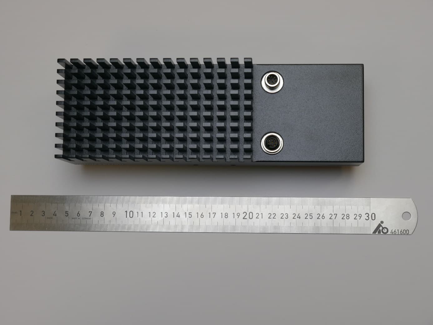
Click to zoom
Application Details
- Equipment Class
- JAB - Part 15 Class B Digital Device
- Date of Grant
- Feb 20, 2020
- Application Purpose
- Original Equipment
- Date of Application
- Feb 19, 2020
- Equipment Note
- 3D camera
- Company
- Roboception GmbH
- Country
- Germany
Documents & Files
Document Text
Text extracted from the exhibit documents filed with the FCC. Open a document above to read the original.
Users Manual
rc_visard Documentation Revision 1.8.1-2-g3c019b5 Roboception GmbH Dec 12, 2019 Contents 1 Introduction1 1.1Overview . . . . . . . . . . . . . . . . . . . . . . . . . . . . . . . . . . . . . . . . . . . . . . .2 1.2Warranty . . . . . . . . . . . . . . . . . . . . . . . . . . . . . . . . . . . . . . . . . . . . . . .3 1.3Applicable standards . . . . . . . . . . . . . . . . . . . . . . . . . . . . . . . . . . . . . . . . .4 1.4Glossary . . . . . . . . . . . . . . . . . . . . . . . . . . . . . . . . . . . . . . . . . . . . . . .6 2 Safety8 2.1General warnings . . . . . . . . . . . . . . . . . . . . . . . . . . . . . . . . . . . . . . . . . . .8 2.2Intended use . . . . . . . . . . . . . . . . . . . . . . . . . . . . . . . . . . . . . . . . . . . . .9 3 Hardware specification10 3.1Scope of delivery . . . . . . . . . . . . . . . . . . . . . . . . . . . . . . . . . . . . . . . . . . .10 3.2Technical specification . . . . . . . . . . . . . . . . . . . . . . . . . . . . . . . . . . . . . . . .11 3.3Environmental and operating conditions . . . . . . . . . . . . . . . . . . . . . . . . . . . . . . .13 3.4Power-supply specifications . . . . . . . . . . . . . . . . . . . . . . . . . . . . . . . . . . . . .13 3.5Wiring . . . . . . . . . . . . . . . . . . . . . . . . . . . . . . . . . . . . . . . . . . . . . . . .14 3.6Mechanical interface . . . . . . . . . . . . . . . . . . . . . . . . . . . . . . . . . . . . . . . . .16 3.7Coordinate frames . . . . . . . . . . . . . . . . . . . . . . . . . . . . . . . . . . . . . . . . . .17 4 Installation19 4.1Installation and configuration . . . . . . . . . . . . . . . . . . . . . . . . . . . . . . . . . . . .19 4.2Power up . . . . . . . . . . . . . . . . . . . . . . . . . . . . . . . . . . . . . . . . . . . . . . .19 4.3Network configuration . . . . . . . . . . . . . . . . . . . . . . . . . . . . . . . . . . . . . . . .19 4.4Discovery ofrc_visarddevices . . . . . . . . . . . . . . . . . . . . . . . . . . . . . . . . . . .20 4.5Web GUI . . . . . . . . . . . . . . . . . . . . . . . . . . . . . . . . . . . . . . . . . . . . . . .22 5 Therc_visardin a nutshell24 5.1Stereo vision . . . . . . . . . . . . . . . . . . . . . . . . . . . . . . . . . . . . . . . . . . . . .24 5.2Sensor dynamics . . . . . . . . . . . . . . . . . . . . . . . . . . . . . . . . . . . . . . . . . . .25 5.3Calibration relative to a robot . . . . . . . . . . . . . . . . . . . . . . . . . . . . . . . . . . . .26 6 Software components27 6.1Stereo camera . . . . . . . . . . . . . . . . . . . . . . . . . . . . . . . . . . . . . . . . . . . .28 6.2Stereo matching . . . . . . . . . . . . . . . . . . . . . . . . . . . . . . . . . . . . . . . . . . .33 6.3Sensor dynamics . . . . . . . . . . . . . . . . . . . . . . . . . . . . . . . . . . . . . . . . . . .40 6.4Visual odometry . . . . . . . . . . . . . . . . . . . . . . . . . . . . . . . . . . . . . . . . . . .45 6.5Stereo INS . . . . . . . . . . . . . . . . . . . . . . . . . . . . . . . . . . . . . . . . . . . . . .47 6.6Camera calibration . . . . . . . . . . . . . . . . . . . . . . . . . . . . . . . . . . . . . . . . . .48 6.7Hand-eye calibration . . . . . . . . . . . . . . . . . . . . . . . . . . . . . . . . . . . . . . . . .54 7 Optional software components67 7.1SLAM . . . . . . . . . . . . . . . . . . . . . . . . . . . . . . . . . . . . . . . . . . . . . . . .67 7.2IO and Projector Control . . . . . . . . . . . . . . . . . . . . . . . . . . . . . . . . . . . . . . .72 7.3TagDetect . . . . . . . . . . . . . . . . . . . . . . . . . . . . . . . . . . . . . . . . . . . . . . .74 7.4ItemPick and BoxPick . . . . . . . . . . . . . . . . . . . . . . . . . . . . . . . . . . . . . . . .83 7.5SilhouetteMatch . . . . . . . . . . . . . . . . . . . . . . . . . . . . . . . . . . . . . . . . . . . 104 i 8 Interfaces118 8.1GigE Vision 2.0/GenICam image interface . . . . . . . . . . . . . . . . . . . . . . . . . . . . . 118 8.2REST-API interface . . . . . . . . . . . . . . . . . . . . . . . . . . . . . . . . . . . . . . . . . 127 8.3The rc_dynamics interface . . . . . . . . . . . . . . . . . . . . . . . . . . . . . . . . . . . . . . 161 8.4KUKA Ethernet KRL Interface . . . . . . . . . . . . . . . . . . . . . . . . . . . . . . . . . . . 164 8.5Time synchronization . . . . . . . . . . . . . . . . . . . . . . . . . . . . . . . . . . . . . . . . 171 9 Maintenance173 9.1Lens cleaning . . . . . . . . . . . . . . . . . . . . . . . . . . . . . . . . . . . . . . . . . . . . . 173 9.2Camera calibration . . . . . . . . . . . . . . . . . . . . . . . . . . . . . . . . . . . . . . . . . . 173 9.3Updating the firmware . . . . . . . . . . . . . . . . . . . . . . . . . . . . . . . . . . . . . . . . 173 9.4Restoring the previous firmware version . . . . . . . . . . . . . . . . . . . . . . . . . . . . . . . 175 9.5Rebooting therc_visard. . . . . . . . . . . . . . . . . . . . . . . . . . . . . . . . . . . . . . . 175 9.6Updating the software license . . . . . . . . . . . . . . . . . . . . . . . . . . . . . . . . . . . . 175 9.7Downloading log files . . . . . . . . . . . . . . . . . . . . . . . . . . . . . . . . . . . . . . . . 176 10 Accessories177 10.1 Connectivity kit . . . . . . . . . . . . . . . . . . . . . . . . . . . . . . . . . . . . . . . . . . . 177 10.2 Wiring . . . . . . . . . . . . . . . . . . . . . . . . . . . . . . . . . . . . . . . . . . . . . . . . 177 10.3 Spare parts . . . . . . . . . . . . . . . . . . . . . . . . . . . . . . . . . . . . . . . . . . . . . . 178 11 Troubleshooting179 11.1 LED colors . . . . . . . . . . . . . . . . . . . . . . . . . . . . . . . . . . . . . . . . . . . . . . 179 11.2 Hardware issues . . . . . . . . . . . . . . . . . . . . . . . . . . . . . . . . . . . . . . . . . . . 179 11.3 Connectivity issues . . . . . . . . . . . . . . . . . . . . . . . . . . . . . . . . . . . . . . . . . . 180 11.4 Camera-image issues . . . . . . . . . . . . . . . . . . . . . . . . . . . . . . . . . . . . . . . . . 180 11.5 Depth/Disparity, error, and confidence image i…
Text truncated - open the document above for the full version.
Users Manual
Warning:A large error during verification can be due to miscalibrated cameras, an inaccurate calibration grid, or wrong grid width or height. Please make sure that the grid is accurate and the entered grid width and height are correct. Otherwise, manual calibration will actually decalibrate the cameras! Step 3: Performing calibration The camera’s exposure time should be set appropriately before starting the calibration. To achieve good calibration results, the images should be well-exposed and image noise should be avoided. Thus, the maximum auto-exposure time should be great enough to achieve a very small gain factor, ideally 0.0 dB. The gain factor is displayed below the camera images as shown in Fig. 6.6.3. Fig. 6.6.3: Starting the calibration procedure For calibration, the grid has to be held in certain poses. The arrows from the grid corners to the green areas indicate that all grid corners should be placed inside the green areas. The green areas are called sensitive areas. TheSize of Sensitive Areaslider can control their size to ease calibration as shown in the screen shot in Fig. 6.6.3. However, please be aware that increasing their size too much may result in slightly less calibration accuracy. 6.6. Camera calibration51 Holding the grid upside down is a common mistake made during calibration. Spotting this in this case is easy because the green lines from the grid corners into the green areas will cross each other as shown in Fig. 6.6.4. Fig. 6.6.4: Wrongly holding the grid upside down leads to crossed green lines. Note:Calibration might appear cumbersome as it involves holding the grid in certain predefined poses. How- ever, only this can ensure an unbiased, high-quality calibration result. Monocalibration Full calibration consists of calibrating each camera individually and then performing a stereo calibration to deter- mine the relationship between them. In most cases, the intrinsic calibration of each camera does not get corrupted. For this reason,Skip Monocalibrationin theCalibratetab should be clicked to skip monocalibration during the first recalibration. Continue with the guidelines given inStereo calibration. If stereo calibration yields an unsatis- factory calibration error, then calibration should be repeated without skipping monocalibration. The monocalibration process involves five poses for each camera as shown in Fig. 6.6.5. Fig. 6.6.5: Poses required for monocamera calibration After the corners or sides of the grid are placed on top of the sensitive areas, the process automatically shows the next pose required. When the process is finished for the left camera, the same procedure is repeated for the right one. Stereo calibration After monocalibration is completed or has been skipped, the stereo calibration process is started. During stereo calibration, both cameras are calibrated to each other to find their relative rotation and translation. 6.6. Camera calibration52 First, the grid should be held closer than 40 cm from the sensor. It must be fully visible in both images and the cameras should look perpendicularly onto the grid. A green outline that stays in the image indicates the images’ acceptance. Fig. 6.6.6: Holding the grid closer than 40 cm during stereo calibration Next, the grid should be held at least 1 m from the cameras. The small cross in the middle of the images should be inside of the grid and the cameras must look perpendicularly onto the grid. A green outline that stays in the image indicates the images’ acceptance. Fig. 6.6.7: Holding the grid farther away than 1 m during stereo calibration Note:If the check marks on the calibration grid all vanish, then either the camera does not look perpendicularly onto the grid, the green cross in the middle of the images is not inside the grid, or the grid is too far away from the camera. Step 4: Storing the calibration result Clicking theCompute Calibrationbutton finishes the process and displays the final result. The presented result is the mean reprojection error of all calibration points. It is given in pixels and typically has a value around 0.3. Note:The given result is the minimum error left after calibration. The real error is definitely not less than this, but could in theory be larger. This is true for every camera-calibration algorithm and the reason why we enforce holding the grid in very specific poses. Doing so ensures that the real calibration error cannot significantly exceed the reported error. PressingSave Calibrationapplies the calibration and saves it to the sensor. Warning:If a hand-eye calibration was stored on therc_visardbefore camera calibration, the hand-eye calibration values could have become invalid. Please repeat the hand-eye calibration procedure. 6.6.3 Parameters The component is calledrc _ stereocalibin the REST-API. 6.6. Camera calibration53 Note:The camera calibration component’s available parameters and status values are for internal use only and may change in the future without further notice. Calibration should only be performed through the Web GUI as described above. 6.6.4 Services Note:The camera calibration component’s available service calls are for internal use only and may change in the future without further notice. Calibration should only be performed through the Web GUI as described above. 6.7 Hand-eye calibration For applications, in which therc_visardis integrated into one or more robot systems, it needs to be calibrated w.r.t. some robot reference frames. For this purpose, therc_visardis shipped with an on-board calibration routine called thehand-eye calibrationcomponent. Note:The implemented calibration routine is completely agnostic about the user-defined robot frame to which therc_visardis calibrated. It might be a robot’s end-effector (e.g., flange or tool center point) or any point on the robot structure. The method’s only requirement is that the pose (i.e., translation and rotation) of this robot frame w.r.t. a user-defined external reference frame (e.g…
Text truncated - open the document above for the full version.
Users Manual
Fig. 6.7.9: Result of the hand-eye calibration process displayed in the Web GUI 6.7.4 Parameters The hand-eye calibration component is calledrc _ hand _ eye _ calibrationin the REST-API and is represented by theHand-Eye Calibrationtab in theWeb GUI(Section 4.5). The user can change the calibration parameters there or use theREST-API interface(Section 8.2). Parameter overview This component offers the following run-time parameters. Table 6.7.1: Therc _ hand _ eye _ calibrationcomponent’s run-time pa- rameters NameTypeMinMaxDefaultDescription grid _ heightfloat640.010.00.0The height of the calibration pattern in meters grid _ widthfloat640.010.00.0The width of the calibration pattern in meters robot _ mountedboolFalseTrueTrueWhether the camera is mounted on the robot This component reports no status values. 6.7. Hand-eye calibration62 Description of run-time parameters The parameter descriptions are given with the corresponding Web GUI names in brackets. grid _ width(Grid Width (m))Width of the calibration grid in meters. The width should be measured with a very great accuracy, preferably with sub-millimeter accuracy. grid _ height(Grid Height (m))Height of the calibration grid in meters. The height should be measured with a very great accuracy, preferably with sub-millimeter accuracy. robot _ mounted(Sensor Mounting)If set to 1, therc_visardis mounted on the robot. If set to 0, therc_visard is mounted statically and the calibration grid is mounted on the robot. (Pose)For convenience, the user can choose in the Web GUI between calibration inXYZABCformat or in XYZ+quaternionformat (seePose formats, Section 13.1). When calibrating using the REST-API, the cali- bration result will always be given inXYZ+quaternion. 6.7.5 Services The REST-API service calls offered to programmatically conduct the hand-eye calibration and to store or restore this component’s parameters are explained below. save _ parametersWith this service call, the current parameter settings of the hand-eye calibration component are persisted to therc_visard. That is, these values are applied even after reboot. This service requires no arguments. This service returns no response. reset _ defaultsrestores and applies the default values for this component’s parameters (“factory reset”). Does not affect the calibration result itself or any of theslotssaved during calibration. Only parameters such as the grid dimensions and the mount type will be reset. Warning:The user must be aware that calling this service causes the current parameter settings to be irrecoverably lost. This service requires no arguments. This service returns no response. set _ poseprovides a robot pose as calibration pose to the hand-eye calibration routine. This service requires the following arguments: { "pose": { "orientation": { "w": "float64", "x": "float64", "y": "float64", "z": "float64" }, "position": { "x": "float64", "y": "float64", "z": "float64" } }, "slot": "int32" } This service returns the following response: 6.7. Hand-eye calibration63 { "message": "string", "status": "int32", "success": "bool" } Theslotargument is used to assign numbers to the different calibration poses. At each instant when set _ poseis called, an image is recorded. This service call fails if the grid was undetectable in the current image. Table 6.7.2: Return codes of theset _ poseservice call statussuccessDescription 1truepose stored successfully 3truepose stored successfully; collected enough poses for calibration, i.e., ready to calibrate 4falsecalibration grid was not detected, e.g., not fully visible in camera image 8falseno image data available 12falsegiven orientation values are invalid reset _ calibrationdeletes all previously provided poses and corresponding images. The last saved calibration result is reloaded. This service might be used to (re-)start the hand-eye calibration from scratch. This service requires no arguments. This service returns the following response: { "message": "string", "status": "int32", "success": "bool" } calibratecalculates and returns the hand-eye calibration transformation with the robot poses configured by the set _ poseservice. Note:For calculating the hand-eye calibration transformation at least three robot calibration poses are required (seeset _ poseservice). However, four calibration poses are recommended. This service requires no arguments. This service returns the following response: { "error": "float64", "message": "string", "pose": { "orientation": { "w": "float64", "x": "float64", "y": "float64", "z": "float64" }, "position": { "x": "float64", "y": "float64", "z": "float64" } }, "robot _ mounted": "bool", "status": "int32", (continues on next page) 6.7. Hand-eye calibration64 (continued from previous page) "success": "bool" } Table 6.7.3: Return codes of thecalibrateservice call statussuccessDescription 0truecalibration successful; returned resulting calibration pose 1falsenot enough poses to perform calibration 2falsecalibration result is invalid, please verify the input data 3falsegiven calibration grid dimensions are not valid save _ calibrationpersistently saves the result of hand-eye calibration to therc_visardand overwrites the ex- isting one. The stored result can be retrieved any time by theget _ calibrationservice. This service requires no arguments. This service returns the following response: { "message": "string", "status": "int32", "success": "bool" } Table 6.7.4: Return codes of thesave _ calibrationservice call statussuccessDescription 0truecalibration saved successfully 1falsecould not save calibration file 2falsecalibration result is not available remove _ calibrationremoves the persistent hand-eye calibration on therc_visard.After this call the get _ calibrationservice reports again that no hand-eye calibration is available. This service requires no arguments. This service returns the following response: { "message": "string", "status": "int32", "success": "bool" } Table 6.7.5: Return codes of theget _ calibra…
Text truncated - open the document above for the full version.
Test Report
Trade Register Munich HRB 85742 VAT ID No. DE129484267 Information pursuant to Section 2(1) DL-InfoV (Germany) at www.tuev-sued.com/imprint Managing Directors: Dr. Peter Havel (CEO) Dr. Jens Butenandt Phone: +49 (0) 9421 55 22-0 Fax: +49 (0) 9421 55 22-99 www.tuev-sued.de TÜV SÜD Product Service GmbH Äußere Frühlingstraße 45 94315 Straubing Germany TÜV SÜD Product Service RESPONSIBLE FOR NAME DATE SIGNATURE Project Management Matthias Stumpe 2020-02-05 SIGN-ID 326728 Authorised Signatory Martin Steindl 2020-02-05 SIGN-ID 327006 Signatures in this approval box have checked this document in line with the requirements of TÜV SÜD Product Service document control rules. ENGINEERING STATEMENT The measurements shown in this report were made in accordance with the procedures described on test pages. All reported testing was carried out on a sample equipment to demonstrate limited compliance with FCC 47 CFR Part 15C. The sample tested was found to comply with the requirements defined in the applied rules. RESPONSIBLE FOR NAME DATE SIGNATURE Testing Matthias Stumpe 2020-02-05 SIGN-ID 326728 Laboratory Accreditation DAkkS Reg. No. D-PL-11321-11-02 Laboratory recognition Registration No. BNetzA-CAB-16/21-15 Industry Canada test site registration 3050A-2 EXECUTIVE SUMMARY A sample of this product was tested and found to be compliant with FCC 47 CFR Part 15B. Report on the FCC and IC Testing of the Roboception GmbH Measuring System. Model: rc_visard In accordance with FCC 47 CFR Part 15B Prepared for: Roboception GmbH Kaflerstraße 2 81241 München Germany FCC ID: 2AVMTRCV17 COMMERCIAL-IN-CONFIDENCE Date: 2020-02-05 Document Number: TR-43340-76881-01 | Issue: 02 DISCLAIMER AND COPYRIGHT This non-binding report has been prepared by TÜV SÜD Product Service with all reasonable skill and care. The document is confidential to the potential Client and TÜV SÜD Product Service. No part of this document may be reproduced without the prior written approval of TÜV SÜD Product Service. © 2020 TÜV SÜD Product Service. ACCREDITATION Our BNetzA Accreditation does not cover opinions and interpretations and any expressed are outside the scope of our BNetzA Accreditation. Results of tests not covered by our BNetzA Accreditation Schedule are marked NBA (Not BNetzA Accredited). Document Number: TR-43340-76881-01 | Issue: 02 COMMERCIAL-IN-CONFIDENCE COMMERCIAL-IN-CONFIDENCE Page 1 of 12 Contents 1 Report Summary .........................................................................................................................2 1.1 Report Modification Record ...........................................................................................................2 1.2 Introduction ....................................................................................................................................2 1.3 Brief Summary of Results .............................................................................................................3 1.4 Declaration of Build Status ............................................................................................................4 1.5 Application Form ...........................................................................................................................4 1.6 Product Information .......................................................................................................................4 1.7 Deviations from the Standard ........................................................................................................4 1.8 EUT Modification Record ..............................................................................................................4 1.9 Test Location .................................................................................................................................4 2 Test Details ..................................................................................................................................5 2.1 Radiated Emissions and Conducted emission ..............................................................................5 3 Photographs ............................................................................................................................. 11 3.1 Equipment Under Test (EUT) ..................................................................................................... 11 4 Test Equipment Information ................................................................................................... 12 4.1 General Test Equipment Used ................................................................................................... 12 Document Number: TR-43340-76881-01 | Issue: 02 COMMERCIAL-IN-CONFIDENCE COMMERCIAL-IN-CONFIDENCE Page 2 of 12 1 Report Summary 1.1 Report Modification Record Alterations and additions to this report will be issued to the holders of each copy in the form of a complete document. Issue Description of Change Date of Issue 1 First Issue 2020-01-09 2 Update FCC ID, Measuring model rc_visard 2020-02-05 Table 1 1.2 Introduction Applicant Roboception GmbH Manufacturer Roboception GmbH Model Number(s) Roboception rc_visard 160m - 4 Serial Number(s) 03048624 Hardware Version(s) V02 Software Version(s) 1.8.3 Number of Samples Tested 1 Test Specification/Issue/Date FCC 47 CFR Part 15B Test Plan/Issue/Date --- Order Number Date 713176881 2019-12-11 Date of Receipt of EUT 2019-12-16 Start of Test 2020-01-07 Finish of Test 2020-01-09 Name of Engineer(s) Matthias Stumpe, Patrick Müller Related Document(s) --- Document Number: TR-11245-66948-01 | Issue: 02 COMMERCIAL-IN-CONFIDENCE COMMERCIAL-IN-CONFIDENCE Page 3 of 12 1.3 Brief Summary of Results A brief summary of the tests carried out in accordance with FCC 47 CFR Part 15B is shown below. Section Specification Clause Test Description Result Comments/Base Standard Configuration and Mode: 120 V AC Powered 2.1 15.109 and 15.107 Radiated Emission and conducted emission Pass ANSI C63.4-2014 Table…
Text truncated - open the document above for the full version.
Test Setup Photos
8WL]UNV\!B]UKNZ4!GE'++,./'003.2'*+!c!>[[]N4!*,! '7CB;>89B79! ! ! 7CAA9E7>5@'>B'7CB;>89B79!DJPN!++!WO!+,! ! 3 Photographs 3.1 Equipment Under Test (EUT) Figure 1 - Radiated emissions Figure 3 c Conducted emission
Contact Information
Applicant
Michael Suppa
Test Firm
TUV SUD Product Service GmbHMarkus Biberger
Technical Specifications
| # | Rule Parts | Frequency Range | Power Output |
|---|---|---|---|
| 1 | 15B | - | - |