2AVNLFYC001001Wireless Remote Controller
Hanwang Technology Co., Ltd.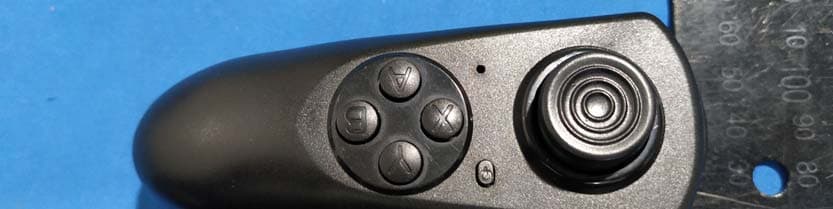
Click to zoom
Application Details
- Equipment Class
- DTS - Digital Transmission System
- Date of Grant
- Mar 23, 2020
- Application Purpose
- Original Equipment
- Date of Application
- Mar 23, 2020
- Equipment Note
- Wireless Remote Controller
- Frequency Range
- 2424.00000000 - 2472.00000000
- Company
- Hanwang Technology Co., Ltd.
- Country
- China
Documents & Files
Document Text
Text extracted from the exhibit documents filed with the FCC. Open a document above to read the original.
Users Manual
Go Go Bird User Manual 1 How to remove and charge lithium battery a. Turn off the switch at the bottom of Go Go Bird, pull out lithium battery from the tail of Go Go Bird, refer to figure 1. b. Plug lithium battery directly into USB charger, charger can be connected to adaptor, computer etc., DC 5.0V power supply, refer to figure 2. c. The green signal light of the charger is on, indicating that power is on; after inserting lithium battery, red signal light is on, indicating that the battery is charging; red signal light is off, indicating that the lithium battery is full. d. After charging finished, unplug the charger from DC 5.0V power supply and extract the lithium battery promptly. e. Plug the full lithium battery into the battery container, tail of Go Go Bird, pay attention to the insertion direction, refer to figure 3. 2 How to insert and remove AAA batteries of remote control a. Turn off the switch of the remote control, extract the battery cover,refer to figure 4. b. Insert two 1.5V AAA batteries correctly based on polarity identification into battery compartment. c. Reload battery cover, it is loaded correctly when you hear a slight click. Remote control will automatically turn off in ten minutes when not in use. d. For AAA batteries that running out of power, please remove from battery cover. Lithium battery Pull out On/off switch Figure 1 Figure 2 USB ChargerLithium battery Figure 3 Figure 5 Function button On/off switch Signal light Turn around button 3 How to pair Go Go Bird with remote control Go Go bird already matched when leaving factory, if remote control can connect with Go Go Bird, please ignore this step. If not, please refer to below pairing steps. a. Turn on the switch of Go Go Bird and place the remote control close to Go Go Bird. b. Press the function button and turn around button (B) of the remote control at the same time (remote control should be off), then press the switch button of remote control, then the signal light of remote control will be on,refer to figure 5. c. Pay attention to the signal light of Go Go Bird, if the signal light is flashing, indicating that the pairing matching is successful. If fail to match, please repeat above steps. Figure 4 4 How to monitor remote control a. Pull up the rocker (upwards), Go Go Bird will speed up; move down the rocker (downwards), Go Go Bird will slow down, refer to figure 6. b. Move the rocker to the left (left), Go Go Bird will turn left; move the rocker to the right (right), Go Go Bird will turn right. c. Press the button A, Go Go Bird will keep flying in circle counter clockwise; press button Y, Go Go Bird will keep flying in circle clockwise. d. Press button B, Go Go Bird will turn around. When Go Go Bird is flying, press button X, Go Go Bird will descend. e. The IR evading obstacle function, as default setting, will be on when Go Go Bird fly. You can turn on/off this IR evading obstacle function by pressing function button and turn around (B) button of remote control at the same time for better user experience. Figure 6 Pull up Turn leftTurn right Move down X: take-off/landing A: Counter clockwise Y: Clockwise B: turn around 5 How to fly Go Go Bird The right way to hold Go Go Bird, refer to figure 7. How to take off: Method 1. By somatosensory switch: Turn on the switch of Go Go Bird, hold Go Go Bird on horizontal level, sway up-and-down, wings start to flap then release, Go Go Bird will fly away. Method 2. By remote control: Turn on the switch of Go Go Bird and remote control, hold Go Go Bird on horizontal level, press button X of remote control, wings start to flap then release, Go Go Bird will fly away. a. The default altitude setting is to fly straight, after Go Go Bird fly away, please use remote control rocker to monitor the direction. b. Go Go Bird is with altitude hold sensor, when you fly Go Go Bird, please hold it higher with your hand then release, Go Go Bird will be on auto fly mode. Then please use remote control to monitor. Figure 7 6 Malfunction & solution No response when turn on the remote control Solution: Double check whether AAA batteries install correctly according to the polarity identification, or replace with new batteries. No response or lack of power when turn on Go Go Bird Solution: Make sure the lithium battery of Go Go Bird is fully charged. Remote control fail to connect with Go Go Bird Solution: Turn off Go Go Bird and remote control, repeat the pairing steps. Type of emissionsSRD Frequency2424MHz-2472MHz 7 Short-range wireless transmission equipment Product nameBionic flapping-wing bird 8 Warnings a. When you take out Go Go Bird from the box, try not to grab the wings and tails, keep Go Go Bird away from thermal source, sharp objects. b. For multiple Go Go Bird playing, please pair one with one individually, do not turn on the switch of two Go Go Birds and pair at the same time. c. Please keep Go Go Bird within your sight when Go Go Bird is flying. When Go Go Bird is on flying mode, keep Go Go Bird away from water, trees, high voltage wire etc,. d. Press on/off or button X in emergency, Go Go Bird will stop flying immediately and drop on the ground. Please check the wires, plug, shell and other parts regularly. If there is any damage please stop using until it is fixed completely. e. Please use the customized lithium batteries that come with Go Go Bird only. Do not match with other lithium batteries. Rechargeable batteries are only to be charged under adult supervision. Rechargeable batteries are to be removed from the toy before being charged. f. AAA batteries are to be inserted into remote control with the correct polarity. Non-chargeable batteries are not to be charged. Different types of batteries or new and used batteries are not to be mixed. Exhausted batteries are to be removed from the toy. The supply terminals are not to be short-circuited. Do not mix old and new batteries. Do not mix alkaline, standard (carbon-zinc), or rechargeable batteries. g. This product is not …
Text truncated - open the document above for the full version.
Cover Letter(s)
Company: Hanwang Technology Co., Ltd. Add: 3rd Floor, Building 5, No. 8 Dongbeiwang West Road, Haidian District, Beijing, China Tel: 010-82788546 Email: [email protected] DATE:2020-1-20 DECLARATION OF SIMILARITY FEDERAL COMMUNICATIONS COMMISSIONS Authorization and Evaluation Division 7435 Oakland Mills Road Columbia, MD 21046 Dear Sir or Madam: We Hanwang Technology Co., Ltd., Hereby declare that product: Wireless Remote Controller,model(s):FYC 102,FYC 103,FYC 201,FYC 202,FYC 203,FYC 301,FYC 302,FYC 303,FYC 401,FYC 402,FYC 403,FYC 501,FYC 502,FYC 503,FYC 601,FYC 602,FYC 603,FYC 701,FYC 702,FYC 703,FYC 801,FYC 802,FYC 803,FYC 0101,FYC 001 are electrically identical with the model FYC 101 that was tested by BACL.FCC ID: 2AVNLFYC001001. The differences between the tested model and multiple models are as follows: They have the same PCB layout and schematic, just have different model name for marketing purpose. Please contact me should there be need for any additional clarification or information. Best Regards, Signature: Printed Name: Xuehui Chen Title: Certification Manager
Cover Letter(s)
QA-FR-170-B 7/29/2014 Company: Hanwang Technology Co., Ltd. Add: 3rd Floor, Building 5, No. 8 Dongbeiwang West Road, Haidian District, Beijing, China Tel: 010-82788546 Email: [email protected] DATE:2020-03-10 FCC Authorization FEDERAL COMMUNICATIONS COMMISSIONS Authorization and Evaluation Division 7435 Oakland Mills Road Columbia, MD 21046 Subject: Agent Authorization To whom it may concern: We Hanwang Technology Co., Ltd.,Hereby authorizes Bay Area Compliance Laboratory Corp. to act on its behalf in all matters relating to application for Equipment authorization, including the signing of all documents relating to these matters. All acts carried out by Bay Area Compliance Laboratory Corp. on our behalf shall have the same effect as our own action. We, the undersigned, hereby certify that we are not subject to a denial of federal benefits, that includes FCC benefits, pursuant to Section 5301 of the Anti-Drug Abuse Act of 1988, 21 U.S.C. 862. This authorization is valid until further written notice from the applicant. Sincerely Signature: Printed Name: Xuehui Chen Title: Certification Manager
Cover Letter(s)
QA-FR-171-A Company: Hanwang Technology Co., Ltd. Add: 3rd Floor, Building 5, No. 8 Dongbeiwang West Road, Haidian District, Beijing, China Tel: 010-82788546 Email: [email protected] DATE:2020-03-10 FCC Confidential Authorization FEDERAL COMMUNICATIONS COMMISSIONS Authorization and Evaluation Division 7435 Oakland Mills Road Columbia, MD 21046 Subject: Confidentiality Request regarding application for certification of FCC ID: 2AVNLFYC001001 In accordance with Sections 0.457 and 0.459 of the Commission’s Rules, Hanwang Technology Co., Ltd. hereby requests long-term confidential treatment of information accompanying this application as outlined below: Block Diagram Schematics Operation Description The above materials contain proprietary and confidential information not customarily released to the public.The public disclosure of these materials provides unjustified benefits to its competitors in the market. Sincerely, Signature: Printed Name: Xuehui Chen Title: Certification Manager
External Photos
EXHIBIT B - EUT EXTERNAL PHOTOGRAPHS
ID Label/Location Info
Label location
Internal Photos
EXHIBIT C - EUT INTERNAL PHOTOGRAPHS ANT Chip
Test Report
FCC PART 15.247 TEST REPORT For Hanwang Technology Co., Ltd. 3rd Floor, Building 5, No. 8 Dongbeiwang West Road, Haidian District, Beijing, China Report Type: Original Report Product Type: Wireless Remote Controller Re port Number: RBJ191219050-00 Re port Date: 2020-02-26 Reviewed By: Ivan Cao Assistant Manager Test Laboratory: Bay Area Compliance Laboratories Corp. (Dongguan) No.69 Pulongcun, Puxinhu Industry Area, Tangxia, Dongguan, Guangdong, China Tel: +86-769-86858888 Fax: +86-769-86858891 www.baclcorp.com.cn FCC ID:2AVNLFYC001001 Bay Area Compliance Laboratories Corp. (Dongguan) Report No.: RBJ191219050-00 Page 2 of 27 TABLE OF CONTENTS GENERAL INFORMATION ....................................................................................................................................... 3 PRODUCT DESCRIPTION FOR EQUIPMENT UNDER TEST (EUT) ..................................................................................... 3 OBJECTIVE ................................................................................................................................................................... 3 RELATED SUBMITTAL(S)/GRANT(S) ............................................................................................................................. 3 TEST METHODOLOGY .................................................................................................................................................. 3 MEASUREMENT UNCERTAINTY .................................................................................................................................... 4 TEST FACILITY ............................................................................................................................................................. 4 DECLARATIONS ............................................................................................................................................................ 4 SYSTEM TEST CONFIGURATION .......................................................................................................................... 5 DESCRIPTION OF TEST CONFIGURATION ...................................................................................................................... 5 EUT EXERCISE SOFTWARE .......................................................................................................................................... 5 EQUIPMENT MODIFICATIONS ....................................................................................................................................... 6 BLOCK DIAGRAM OF TEST SETUP ................................................................................................................................ 6 SUMMARY OF TEST RESULTS ............................................................................................................................... 7 FCC §15.247 (i) & §1.1310 & §2.1093- RF Exposure ................................................................................................. 8 APPLICABLE STANDARD .............................................................................................................................................. 8 FCC §15.203 - ANTENNA REQUIREMENT ............................................................................................................. 9 APPLICABLE STANDARD .............................................................................................................................................. 9 ANTENNA CONNECTOR CONSTRUCTION ...................................................................................................................... 9 FCC §15.209, §15.205 & §15.247(d) - SPURIOUS EMISSIONS ............................................................................. 10 APPLICABLE STANDARD ............................................................................................................................................ 10 EUT SETUP ................................................................................................................................................................ 10 EMI TEST RECEIVER & SPECTRUM ANALYZER SETUP .............................................................................................. 11 TEST PROCEDURE ...................................................................................................................................................... 11 CORRECTED AMPLITUDE & MARGIN CALCULATION ................................................................................................. 11 TEST EQUIPMENT LIST AND DETAILS ......................................................................................................................... 12 TEST DATA ................................................................................................................................................................ 12 FCC §15.247(a) (2)–6 dB EMISSION BANDWIDTH .............................................................................................. 18 APPLICABLE STANDARD ............................................................................................................................................ 18 TEST PROCEDURE ...................................................................................................................................................... 18 TEST EQUIPMENT LIST AND DETAILS ......................................................................................................................... 18 TEST DATA ................................................................................................................................................................ 18 FCC §15.247(b) (3) - MAXIMUM PEAK CONDUCTED OUTPUT POWER ...................................................... 21 APPLICABLE STANDARD ................................................................................................................................…
Text truncated - open the document above for the full version.
Test Setup Photos
EXHIBIT D - TEST SETUP PHOTOGRAPHS Radiated Emission Below 1GHz View Radiated Emission Above 1GHz View
Contact Information
Applicant
Xuehui Chen(Certification Manager)
Test Firm
Bay Area Compliance Laboratories Corp.(Dongguan)David Zhang
[email protected]0086 0769 86858888
Technical Specifications
| # | Rule Parts | Frequency Range | Power Output |
|---|---|---|---|
| 1 | 15C | 2.42 GHz - 2.47 GHz | 2.50 mW |
Other Applications from Hanwang Technology Co., Ltd.
2AVNLHWZYN10
Dec 28, 2022e.note
Equipment Class
DSS - Part 15 Spread Spectrum Transmitter
2AVNLFYCG01102
Jun 27, 2020Wireless Remote Controller
Equipment Class
DXT - Part 15 Low Power Transceiver, Rx Verified
2AVNLGGBG01102
Jun 27, 2020Bionic flapping-wing bird
Equipment Class
DXT - Part 15 Low Power Transceiver, Rx Verified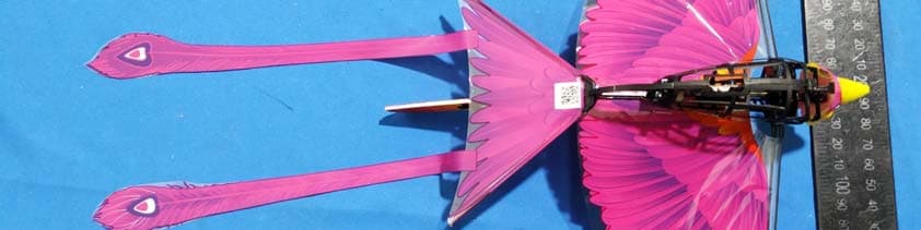
2AVNLGGBD01001
Mar 23, 2020Bionic Flapping-wing Bird
Equipment Class
DTS - Digital Transmission System