2AVNORMICAVrMICA-vibration (RF Sensor Box)
HARTING K.K.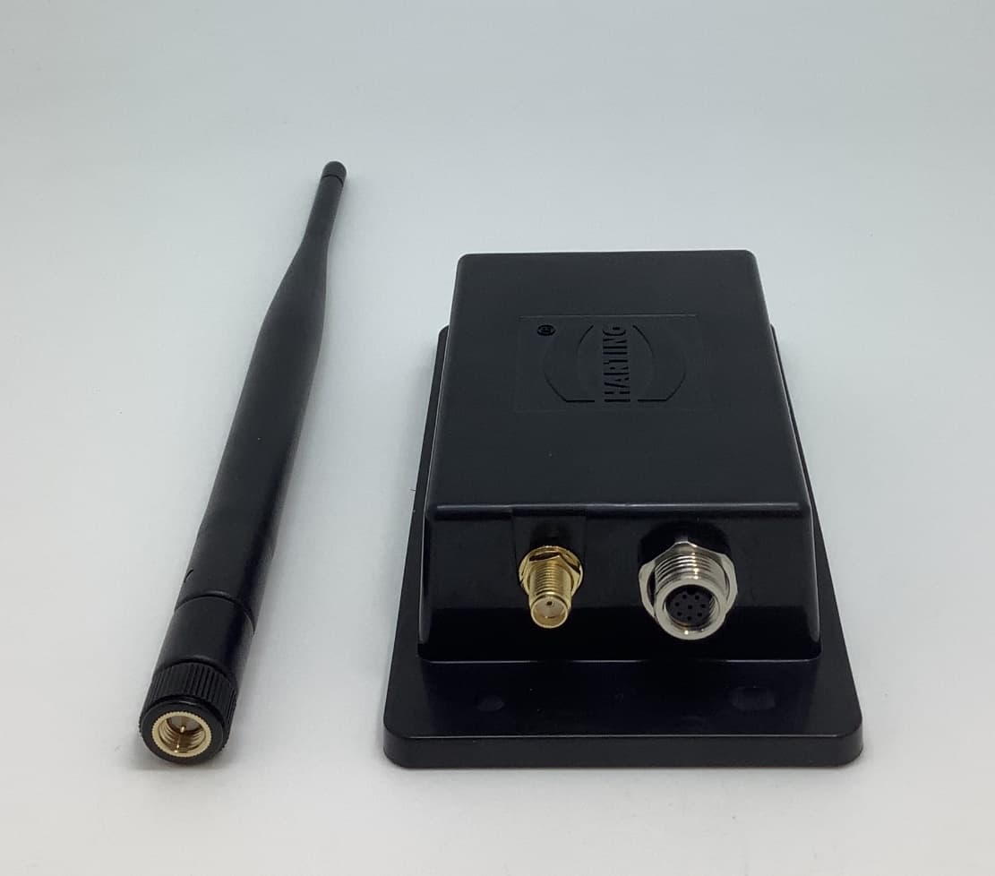
Click to zoom
Application Details
- Equipment Class
- JAD - Part 15 Class A Digital Device
- Date of Grant
- Jan 24, 2021
- Application Purpose
- Original Equipment
- Date of Application
- Jan 24, 2021
- Equipment Note
- rMICA-vibration (RF Sensor Box)
- Company
- HARTING K.K.
- Country
- Japan
Documents & Files
Document Text
Text extracted from the exhibit documents filed with the FCC. Open a document above to read the original.
Users Manual
Motor Condition Monitoring System Manual: Wireless Hardware 1 / 9 Motor Condition Monitoring System User Manual (wireless hardware, US model) USB wireless base station, wireless sensor box, acceleration sensor rMICA-master, rMICA-vibration, sMICA-ACC Ver. 2.0: December 12, 2020 Motor Condition Monitoring System Manual: Wireless Hardware 2 / 9 For safety: For safety use, please read and observe the following contents. The intended users This product has been developed for who in charge of building and maintaining production line. We ask that those have the experience in installing and using the industrial equipment to set up and use this product. Disassembly of product Please never disassemble or process this device case. Not only the waterproof & dustproof performance will be impaired, but it may also cause failure or malfunction. Battery The wireless sensor box (rMICA-vibration) contains the primary battery. Drilling a hole in the case or damaging the case with a sharp tool can damage the battery or cause a short circuit which is extremely dangerous. In addition, the battery cannot be charged, so please do not charge it. Motor Condition Monitoring System Manual: Wireless Hardware 3 / 9 FCC CAUTIONS: This device complies with part15 of the FCC Rules. Operation is subject to the following two conditions: i. This device may not cause harmful inference, and ii. This device msut accept any interference received, including interference that may cause undesired operation. Changes or modifications not expressly approved by the party responsible for compliance could void the user’s authority to operate the equipment. Dedicated HARTING USB cables with three ferrite cores must be used for rMICA- master connection to a host computer in order to meet FCC emission limits. The ferrite core model and positions are as follows: - Mfr/Model: TDK/ZCAT1325-0530A - Position: 2 pcs at nearest position from r-MICA-master, 1 pcs at nearest position from host PC (see below photo) Note: This equipment has been tested and found to comply with the limits for a Class A digital device, pursuant to part 15 of the FCC Rules. These limits are designed to provide reasonable protection against harmful interference when the equipment is operated in a commercial environment. This equipment generates, uses, and can radiate radio frequency energy and, if not installed and used in accordance with the instruction manual, may cause harmful interference to radio communications. Operation of this equipment in a residential area is likely to cause harmful interference in which case the user will be required to correct the interference at his own expense. This transmitter must not be co-located or operated in conjunction with any other antenna or transmitter. This equipment complies with FCC radiation exposure limits set forth for an uncontrolled environment and meets the FCC radio frequency (RF) Exposure Guidelines. This equipment should be installed and operated keeping the radiator at least 23cm or more away from person’s body. Motor Condition Monitoring System Manual: Wireless Hardware 4 / 9 1 Device configuration Wireless motor condition monitoring system consists of the following devices. i. Acceleration sensor probe: sMICA-ACC ii. sMICA-ACC has two built-in MEMS accelerometers (1 axis high frequency + 3 axis) and temperature sensor. The probe is installed directly on the object to be measured (Motor, etc.). sMICA-ACC supplies power and sends sensor signals via a dedicated M8 connector cable (2m). Sensor cable is shielded to minimize the effects from the electromagnetic noise. The range of the accelerometer sensor is ±50g, but in order to increase the resolution, only the ±12.5g portion is acquired by the microcontroller ADC. Please contact us if you need a wider range of acceleration. Remarks: High performance high frequency acceleration measurement axis General acceleration measurement axis iii. Wireless sensor box: rMICA-vibration rMICA-vibration consists of a 32-bit microcomputer STM32 and a 920MHz wireless module, a long-life large capacity battery. One sMICA sensor and the dedicated sensor are connected to rMCIA-vibration. rMICA-vibration starts Sensor connector Motor Condition Monitoring System Manual: Wireless Hardware 5 / 9 measurement at the time set on the host computer WEB GUI (up to 10 times/day). In the measurement, the 16384 sets of acceleration is continuously acquired with a sampling interval of 50μs (2kHz) to transmit the data to rMICA- master. It takes about 5s to send all data. Depending on the signal condition, it may take longer to resend the data. If the transmission of all data is not completed within 30s, the transmission operation will be skipped and the data file for that timing will not be created. By setting the trigger acceleration on the WEB GUI, you can also wait until the measurement target starts moving. If the acceleration value does not reach the trigger acceleration before timeout, the measurement and data transmission is skipped and the data file is not created. In addition, by setting an offset delay time, the measurement is started after a certain period of time after trigger acceleration is detected. The acceleration value is a relative acceleration with the average of the measured data as the 0 point. Therefore, it is not necessary to consider the effect of the gravitational acceleration due to the installation of the acceleration sensor. iv. USB wireless base station: rMICA-master rMICA-master has a built-in 920MHz wireless module and connects to a host computer such as MICA-R via USB2.0. Power (5V) is supplied from the host computer and connect a dedicated antenna to the antenna terminal of the RMA connector. A rMICA-master can accommodate at least 60 rMICA-vibration. More rMICA- vibration can be connected by setting different measurement time to each rMICA-vibration. rMCIA master can only communicate with rMICA-vibration at 1 time, so you should be aware of the r…
Text truncated - open the document above for the full version.
External Photos
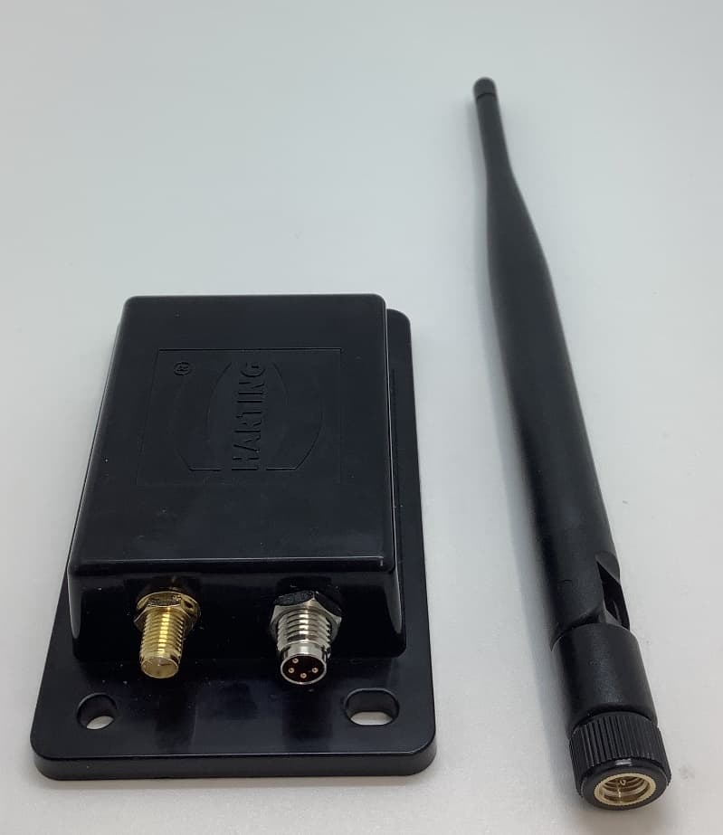
rMICA-vibration Product Photos (Outside) Top view Side views Side views SMA antenna connector Bottom view
ID Label/Location Info
rMICA-vibration
Internal Photos
rMICA-vibration Photos (Inside)
Test Report
Test report No. : 13174068H-R3 Page : 1 of 21 Issued date : January 25, 2021 FCC ID : 2AVNORMICAV UL Japan, Inc. Ise EMC Lab. 4383-326 Asama-cho, Ise-shi, Mie-ken 516-0021 JAPAN Telephone : +81 596 24 8999 Facsimile : +81 596 24 8124 Report Cover Page - 13-EM-F0429 Issue # 17.0 EMI TEST REPORT Test Report No. : 13174068H-R3 Applicant : HARTING K.K. Type of EUT : rMICA-vibration (RF Sensor Box) Model Number of EUT : 72RMICAVIBR11 FCC ID : 2AVNORMICAV Test regulation : FCC Part 15 Subpart B: 2020 Class A Test Result : Complied (Refer to SECTION 3.2) Date of test: November 1, 2020 Representative test engineer: Masaya Minami Engineer Consumer Technology Division Approved by: Shinichi Miyazono Engineer Consumer Technology Division CERTIFICATE 5107.02 The testing in which “Non-accreditation” is displayed is outside the accreditation scopes in UL Japan. There is no testing item of “Non-accreditation”. 1. This test report shall not be reproduced in full or partial, without the written approval of UL Japan, Inc. 2. The results in this report apply only to the sample tested. 3. This sample tested is in compliance with the limits of the above re gulation. 4. The test results in this test report are traceable to the national or international standards. 5. This test report must not be used by the customer to claim product certification, approval, or endorsement by the A2LA accreditation body. 6. This test report covers EMC technical requirements. It does not cover administrative issues such as Manual or non-EMC test related Requirements. (if applicable) 7. The all test items in this test report are conducted by UL Japan, Inc. Ise EMC Lab. 8. The opinions and the interpretations to the result of the description in this report are outside scopes where UL Japan has been accredited. 9. The information provided from the customer for this report is identified in SECTION 1. 10. This report is a revised version of 13174068H-R2. 13174068H-R2 is replaced with this report. Test report No. : 13174068H-R3 Page : 2 of 21 Issued date : January 25, 2021 FCC ID : 2AVNORMICAV UL Japan, Inc. Ise EMC Lab. 4383-326 Asama-cho, Ise-shi, Mie-ken 516-0021 JAPAN Telephone : +81 596 24 8999 Facsimile : +81 596 24 8124 REVISION HISTORY Original Test Report No.: 13174068H Revision Test report No. Date Page revised Contents - (Ori ginal) 13174068H December 17, 2020 - - 1 13174068H-R1 January 18, 2021 P.11 Correction of the Test distance in Clause 5.4; from 3 m to 10 m 1 13174068H-R1 January 18, 2021 P.12 Correction of the Test distance in Figure 2 (1 GHz – 5 GHz drawing); from 3 m to 10 m 1 13174068H-R1 January 18, 2021 P.15, 16 Data replacement by limit correction 2 13174068H-R2 January 20, 2021 P.10 Addition of the No. I and Cable 6 in confi guration diagram and list for Clause 4.2. 2 13174068H-R2 January 20, 2021 P.12 Correction of the Test distance in Figure 2 (1 GHz - 5 GHz drawing); from 10 m to 3 m 3 13174068H-R3 January 25, 2021 P.10 Correction of Model number and Serial number for the No. I and Cable length for No.6 in configuration diagram and list for Clause 4.2; < No. I > From Model number: AD-A240P80 Serial number: 001 To Model number: AD-B240P100 Serial number: 1913 <Cable length for No.6> F rom 1.6 m to 3.6 Test report No. : 13174068H-R3 Page : 3 of 21 Issued date : January 25, 2021 FCC ID : 2AVNORMICAV UL Japan, Inc. Ise EMC Lab. 4383-326 Asama-cho, Ise-shi, Mie-ken 516-0021 JAPAN Telephone : +81 596 24 8999 Facsimile : +81 596 24 8124 Reference: Abbreviations (Including words undescribed in this report) AAN Asymmetric Artificial Network ILAC International Laboratory Accreditation Conference AC Alternating Current ISED Innovation, Science and Economic Development Canada AM Amplitude Modulation ISN Impedance Stabilization Network AMN Artificial Mains Network ISO International Organization for Standardization Amp, AMP Amplifier JAB Japan Accreditation Board ANSI American National Standards Institute LAN Local Area Network Ant, ANT Antenna LCL Longitudinal Conversion Loss AP Access Point LIMS Laboratory Information Management System ASK Amplitude Shift Keying LISN Line Impedance Stabilization Network Atten., ATT Attenuator MRA Mutual Recognition Arrangement AV Average N/A Not Applicable BPSK Binary Phase-Shift Keying NIST National Institute of Standards and Technology BR Bluetooth Basic Rate NS No signal detect. BT Bluetooth NSA Normalized Site Attenuation BT LE Bluetooth Low Energy NVLAP National Voluntary Laboratory Accreditation Program BW BandWidth OBW Occupied Band Width C.F Correction Factor OFDM Orthogonal Frequency Division Multiplexing Cal Int Calibration Interval PK Peak CAV CISPR AV P LT long-term flicker severity CCK Complementary Code Keying POHC(A) Partial Odd Harmonic Current CDN Coupling Decoupling Network Pol., Pola. Polarization Ch., CH Channel PR-ASK Phase Reversal ASK CISPR Comite International Special des Perturbations Radioelectriques P ST short-term flicker severity Corr. Correction QAM Quadrature Amplitude Modulation CPE Customer premise equipment QP Quasi-Peak CW Continuous Wave QPSK Quadri-Phase Shift Keying DBPSK Differential BPSK r.m.s., RMS Root Mean Square DC Direct Current RBW Resolution Band Width DET Detector RE Radio Equipment D-factor Distance factor REV Reverse Dmax maximum absolute voltage change during an observation period RF Radio Frequency DQPSK Differential QPSK RFID Radio Frequency Identifier DSSS Direct Sequence Spread Spectrum RSS Radio Standards Specifications EDR Enhanced Data Rate Rx Receiving e.i.r.p., EIRP Equivalent Isotropically Radiated Power SINAD Ratio of (Signal + Noise + Distortion) to (Noise + Distortion) EM clamp Electromagnetic clamp S/N Signal to Noise ratio EMC ElectroMagnetic Compatibility SA, S/A Spectrum Analyzer EMI ElectroMagnetic Interference SG Signal Generator EMS ElectroMagnetic Susceptibility SVSWR Site-Voltage Standing Wave Ratio EN European Norm THC(A) Total Harmonic Current e.r.p., ERP Effective Radiated Power THD(%) Total Harmonic Distortion …
Text truncated - open the document above for the full version.
Test Setup Photos
Test report No. : 13174068H-R3 Page : 18 of 21 Issued date : January 25, 2021 FCC ID : 2AVNORMICAV UL Japan, Inc. Ise EMC Lab. 4383-326 Asama-cho, Ise-shi, Mie-ken 516-0021 JAPAN Telephone : +81 596 24 8999 Facsimile : +81 596 24 8124 APPENDIX 3: Photographs of test setup Radiated Emission Below 1GHz Photo 1 Photo 2 Test report No. : 13174068H-R3 Page : 19 of 21 Issued date : January 25, 2021 FCC ID : 2AVNORMICAV UL Japan, Inc. Ise EMC Lab. 4383-326 Asama-cho, Ise-shi, Mie-ken 516-0021 JAPAN Telephone : +81 596 24 8999 Facsimile : +81 596 24 8124 Radiated Emission Above 1GHz Photo 1 Photo 2 Test report No. : 13174068H-R3 Page : 20 of 21 Issued date : January 25, 2021 FCC ID : 2AVNORMICAV UL Japan, Inc. Ise EMC Lab. 4383-326 Asama-cho, Ise-shi, Mie-ken 516-0021 JAPAN Telephone : +81 596 24 8999 Facsimile : +81 596 24 8124 Worst Case Position (Module) Above 1 GHz (Horizontal: X-axis / Vertical: X-axis) Below 1 GHz (Horizontal: X-axis / Vertical: X-axis) X-axis Y-axis Z-axis Test report No. : 13174068H-R3 Page : 21 of 21 Issued date : January 25, 2021 FCC ID : 2AVNORMICAV UL Japan, Inc. Ise EMC Lab. 4383-326 Asama-cho, Ise-shi, Mie-ken 516-0021 JAPAN Telephone : +81 596 24 8999 Facsimile : +81 596 24 8124 Worst Case Position (Antenna) Above 1 GHz (X: 0-axis) Below 1 GHz (X: 0-axis) 0-axis 45-axis X90-axis End of Report
Contact Information
Applicant
Kenji Nogata(Managing Director)
Technical Contact
UL Japan, Inc.Shinichi Miyazono
[email protected]81-596-24-8999
4383-326 Asama-cho, Ise-shi · Mie-ken · Japan
Test Firm
UL Japan, Inc.(Ise)Takayuki Shimada
Technical Specifications
| # | Rule Parts | Frequency Range | Power Output |
|---|---|---|---|
| 1 | 15B | - | - |
Other Applications from HARTING K.K.
2AVNORMICAM
Jan 24, 2021rMICA-master (USB RF Receiver)
Equipment Class
JAD - Part 15 Class A Digital Device