2AVNTSOG-BAL-DOTFast wireless car mount
Sinjimoru Co.,Ltd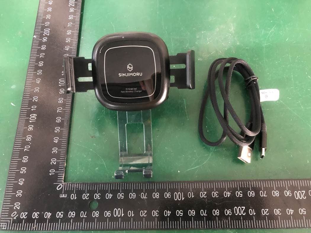
Click to zoom
Application Details
- Equipment Class
- DCD - Part 15 Low Power Transmitter Below 1705 kHz
- Date of Grant
- Jan 19, 2021
- Application Purpose
- Original Equipment
- Date of Application
- Jan 13, 2021
- Equipment Note
- Fast wireless car mount
- Frequency Range
- 0.11000000 - 0.20500000
- Company
- Sinjimoru Co.,Ltd
- Country
- South Korea
Documents & Files
Document Text
Text extracted from the exhibit documents filed with the FCC. Open a document above to read the original.
Users Manual
148.5mm `` 性LH叟罕斗从哲 Guide and Caution 咽召包否已从罕叫从苞 Power supply precautions 1. 对吾斗包世芭人冷音针苛QC2.0王七QC3.01. Forsmooth usage, we recommend us,ng a 大围号人回到人南音过召甘任S\a!L回. QC2.0andQC3.0CigarJack 早包含翌书电色Lff从哲 1. 早洲3mm,却HSmmOl41斗兄空列OI<, 人恬纣音书召苟卫,望早升101尘刊叫叫早召老衬01 对陀屯令双合LICI. 4. 大尼μ扑早芒丘才菩O冷l召早对吾OflOI甘01 世创昔今毁合L回.工召罕芒O忙H21召早斗 旮舍LI卧 -30"COI怂:吾召立迳召土 60"C召辛.早包合召否甘 -BO"C召辛:2-:::t酉钳吾封否XI Wirelesschargingguidelines 1. For phones with case�cases with a thickness of 3mm to 5mm is recommended. For some cases the wireless charging function may be limited. 2.3巴皆丕磕音世号古回,生叶呈芒音丘马世皆叫2. Use the three-way adjustments of the 0-Grab Bal. 否君�I臾引罕�I立(±DI呈芒玉世叫早性合召71Place the smartphone in the center of the 0-Grab 弓世斗早因詈斐卒召夸衬空爸呈封啡20%告世Bal cradle. (The right positioning of the phone can 牛双合L(卧.) increasethechargingefficiencyby20%) 3. 早召老衬D仄l钳么引巨芒叫召早2主召召卫吕3. For smartphonesthatdo not support wireless 王芒世号习01甘01皆创世牛双芒啡,马召罕芒 charging, please note that a 2 seconds wamingtone 啦胆l召早斗召舍L忙I. may occur orthatthe product may have functional 早牡杏袒音01,1钳苟la±DI巨芒 abnormality. Abnormal functionality may occur in 叫目纽红南皂±DI巨芒 the following cases: 叫肖全对包砬匡芒升10伈 Smartphones that do not support wireless charging -Smartphones made out of metal -Smartphone cases made out of metal 4. Please note that in case of high temperatures in the vehicle, the heat may cause the product to malfunction. Take caution inthefollowingcases: -Temperature above 30'C: decrease ofcharging Percentage -Temperature approx. 60-C: interruption of wireless charging -Temperature approx. BO"C: 0-Grab Bal stops operating 0-Grab区 Fast Wireless Charger 对吾人f号昝丐人1包LI卧. This is your product user manual. .2.::J. 翌皆早邑老召平问召卦君皂l 0-Grab Bal wireless charging mounting manual 可呈丕召雀丘沮01叶呈罕包老召才大回詈从号对AIIH. The wireless charging mount can be used right away without any additional assembly. , � r,; 庄 三n ' , ::,,i,,_ 玉 1. 大t碧舍吾干�I2.:! 翌世号刀悍l塌合LICf. l. Insert/place the 0-Grab Bal holding clip in the air vent of the vehicle. 2. 舍吾子才丸cH斗丕告早号昼司舍吾干�I巳甘针对卫召甘LIC十 2. Rotate the fastener on the clip to secure the grip in the air vent. 3. 升101量昼癸2巴豆工凿岂番从邑苞苍上1l7f咎豆呈ILICf. 3. Plug in the cable and the 0-Grab Bal is ready to use 纽1亘芒 才大1号岂 Howto mount the smartphone 卢 』 。 1. 菩司7t刍司以七 世利吾叶芒音音司吾目叶. 五 1. Place the smartphone in the mount when the holder ,s open 2.FOD性人1才生ot巨毛甘号召·x1刮菩司7fXH吾9呈世哲LI吐 2. The FOD sensor will detect the smartphone and the holder then closes automatically. 3菩印归引由生U匡宅01平圉丑舍召01人I硐.,JL四 3. When the holder is closed the phone has been mounted and charging will start automatically. E E SOT FCC Information to User This equipment has been tested and found to comply with the limits for a Class B digital device, pursuant to Part 15 of the FCC Rules. These limits are designed to provide reasonable protection against harmful interference in a residential installation. This equipment generates, uses and can radiate radio frequency energy and, if not installed and used in accordance with the instructions, may cause harmful interference to radio communications. However, there is no guarantee that interference will not occur in a particular installation. If this equipment does cause harmful interference to radio or television reception, which can be determined by turning the equipment off and on, the user is encouraged to try to correct the interference by one of the following measures: • Reorient or relocate the receiving antenna. • Increase the separation between the equipment and receiver. • Connect the equipment into an outlet on a circuit different from that to which the receiver is con-nected. • Consult the dealer or an experienced radio/TV technician for help. Caution Modifications not expressly approved by the party responsible for compliance could void the user’s authority to operate the equipment. FCC Compliance Information : This device complies with Part 15 of the FCC Rules. Operation is subject to the following two conditions: (1) This device may not cause harmful interference, and (2) this device must accept any interference received, including interference that may cause undesired operation.
Cover Letter(s)
SCS-F018: Project and Product Certification Representative Authorization Letter Page 1 of 2 Rev 7.0 775 Montague Expressway Milpitas, CA 95035 Tel: 408-526-1188 Fax: 408-526-1088 Email: [email protected] Website: https://www.cps.bureauveritas.com/ Project and Product Certification Representative Authorization Letter Reason for Amendment (current / obsolete) Revision History Approved Date From To Initial Release (obsolete) 1.0 1.0 Nov-14-2006 Revised wording (obsolete) 1.0 2.0 Sept–25-2007 Updated company template (obsolete) 2.0 3.0 Jan-31-2012 Updated letter information (obsolete) 3.0 4.0 May-23-2014 Added FCC ID field (obsolete) 4.0 5.0 Sep-16-2014 Updated company name & logo (current) 5.0 6.0 Jun-27-2018 Updated References and Contact info 6.0 7.0 Aug-30-202 SCS-F018: Project and Product Certification Representative Authorization Letter Page 2 of 2 Rev 7.0 Sinjimoru Co.,Ltd (2020-12-18) To: BVCPS, INC. 775 Montague Expressway, Milpitas, CA 95035 USA Dear Sir/Madam, Re: Product Certification Representative Authorization Letter We, _____ Sinjimoru Co.,Ltd _____ hereby authorize Bureau Veritas Consumer Product Services, Inc. to act as a Certification Body for certifying for the following project(s): FCC ID: 2AVNTSOG-BAL-DOT Product Description: Fast wireless car mount Model: SOG_WIRE_BAL_BK_DOT Sincerely, HANDAE LIM Sinjimoru Co.,Ltd #321 DMC Hi-tech Industrial Center, Seongam-ro 330, Mapo-gu, Seoul, Korea, 03920.
Cover Letter(s)
SCS-F019: Confidentiality Request Letter Page 1 of 2 Rev 7.0 775 Montague Expressway Milpitas, CA 95035 Tel: 408-526-1188 Fax: 408-526-1088 Email: [email protected] Website: https://www.cps.bureauveritas.com/ Confidentiality Request Letter Reason for Amendment (current / obsolete) Revision History Approved Date From To Initial Release (obsolete) 1.0 1.0 Nov-14-2006 Adding CFR 2.459 (obsolete) 1.0 2.0 August – 11 - 2008 Updated company template & Added text box (obsolete) 2.0 3.0 Jan-31-2012 Added IC confidentiality letter form (obsolete) 3.0 4.0 March-26-2015 Corrections to STC form. Added reference to KDB (obsolete) 4.0 5.0 Nov-19-2015 Updated company logo (current) 5.0 6.0 Jun-26-2019 Updated References and Contact Info 6.0 7.0 Aug-30-2020 SCS-F019: Confidentiality Request Letter Page 2 of 2 Rev 7.0 Sinjimoru Co.,Ltd (2020-12-18) To: Federal Communications Commission Authorization and Evaluation Division 7435 Oakland Mills Road Columbia, MD 21046-1609 Cc: Bureau Veritas Consumer Products Services Inc. 775 Montague Expressway Milpitas, CA 95035 Subject: Confidentiality Request for FCC ID: 2AVNTSOG-BAL-DOT Pursuant to CFR 47 sections 0.457 and 0.459, we respectfully request permanent confidential treatment of the following Exhibits accompanying this application be held confidential: Type of Confidentiality Requested Exhibit Short Term Permanent Block Diagram Short Term External Photos Short Term Permanent i Internal Photos Short Term Permanent Operational Description/ Theory of Operation Short Term Permanent Parts List Short Term Permanent Tune-Up Procedure Short Term Permanent Schematics Short Term Test Setup Photos Short Term Permanent i User’s Manual The above materials contain trade secrets and proprietary information not customarily released to the public. The public disclosure of these materials may be harmful to the applicant and provide unjustified benefits to its competitors. Permanent Confidentiality: The applicant requests the exhibits listed above as permanently confidential be permanently withheld from public review due to materials that contain trade secrets and proprietary information not customarily released to the public. Short-Term Confidentiality: To avoid premature release of sensitive information prior to marketing or release of the product to the public, the applicant requests the following documents contained in this certification application be temporarily withheld from public disclosure for an initial period of 45 or 180 days; or for a specified date of not to exceed 180 days from the Grant Date The applicant understands that disclosure of this application and all accompanying documentation will not be made before the date of the Grant for this application. Sincerely, HANDAE LIM Sinjimoru Co.,Ltd #321 DMC Hi-tech Industrial Center, Seongam-ro 330, Mapo-gu, Seoul, Korea, 03920. i Permanent confidentiality may be requested in accordance with FCC KDB 726920
ID Label/Location Info
Label location
Internal Photos
ANTENNA
RF Exposure Info
1 / 18 EUT Specification FCC ID: 2AVNTSOG-BAL-DOT Characteristics Description Product Name Fast wireless car mount Model number SOG_WIRE_BAL_BK_DOT Power Supply AC120V/60Hz for car charger Operating Frequency Range 110-205KHz Modulation Technique ASK Antenna Type Induction coil Device category Portable (<20cm separation) Mobile (>20cm separation) Others ___ Exposure classification Occupational/Controlled exposure (S = 5mW/cm2) General Population/Uncontrolled exposure (S=1mW/cm2) Antenna diversity Single antenna Multiple antennas Tx diversity Rx diversity Tx/Rx diversity Evaluation applied MPE Evaluation SAR Evaluation Applicable Standard: FCC Part 1(1.1310) ,Part 2(2.1091) and KDB 680106 D01 RF Exposure Wireless Charging Apps v03 Applicable Requirement: Three different categories of transmitters are defined by the FCC in OET Bulletin 65. These categories are fixed installation, mobile, and portable and are 2 / 18 defined as follows: Fixed Installations: fixed location means that the device, including its antenna, is physically secured at a permanent location and is not able to be easily moved to another location. Additionally, distance to humans from the antenna is maintained to at least 2 meters. Mobile Devices: a mobile device is defined as a transmitting device designed to be used in other than fixed locations and to be generally used in such a way that a separation distance of at least 20 centimeters is normally maintained between the transmitter's radiating structures and the body of the user or nearby persons. Transmitters designed to be used by consumers or workers that can be easily re-located, such as a wireless modem operating in a laptop computer, are considered mobile devices if they meet the 20 centimeter separation requirement. The FCC rules for evaluating mobile devices for RF compliance are found in 47 CFR §2.1091. Portable Devices: a portable device is defined as a transmitting device designed to be used so that the radiating structure(s) of the device is/are within 20 centimeters of the body of the user. Portable device requirements are found in Section 2.1093 of the FCC's Rules (47 CFR§2.1093). The FCC also categorizes the use of the device as based upon the user’s awareness and ability to exercise control over his or her exposure. The two categories defined are Occupational/ Controlled Exposure and General Population/Uncontrolled Exposure. These two categories are defined as follows: Occupational/controlled exposure limits apply in situations in which persons are exposed as a consequence of their employment provided those persons are fully aware of the potential for exposure and can exercise control over their exposure. Limits for occupational/controlled exposure also apply in situations when a person is transient through a location where occupational/controlled limits apply provided he or she is made aware of the potential for exposure. The phrase fully aware in the context of applying these exposure limits means that an exposed person has received written and/or verbal information fully explaining the potential for RF exposure resulting from his or her employment. With the exception oftransient persons, this phrase also means that an exposed person has received appropriate training regarding work practices relating to controlling or mitigating his or her exposure. Such training is not required for transient persons, but they must receive written and/or verbal information and notification (for example, using signs) concerning their exposure potential and appropriate means available to mitigate their exposure. The phrase exercise control means that an exposed person is allowed to and knows how to reduce or avoid exposure by administrative or engineering controls and work practices, such as use of personal protective equipment or time averaging of exposure. General population/uncontrolled exposure limits apply in situations in which the general public may be exposed, or in which persons who are 3 / 18 exposed as a consequence of their employment may not be fully aware of the potential for exposure or cannot exercise control over their exposure. Licensees and applicants are responsible for compliance with both the occupational/controlled exposure limits and the general population/uncontrolled exposure limits as they apply to transmitters under their jurisdiction. Licensees and applicants should be aware that the occupational/controlled exposure limits apply especially in situations where workers may have access to areas in very close proximity to antennas and access to the general public may be restricted. In lieu of evaluation with the general population/uncontrolled exposure limits, amateur licensees authorized under part 97 of this chapter and members of his or her immediate household may be evaluated with respect to the occupational/controlled exposure limits in this section, provided appropriate training and information has been provided to the amateur licensee and members of his/her household. Other nearby persons who are not members of the amateur licensee's household must be evaluated with respect to the general population/uncontrolled exposure limits. Test Procedure 1.EUT was placed on a table, and the measure probe was placed at a measurement distance of 0~10cm from the EUT to the center of the probe. 2.Power on the measuring probe, the EUT was set at the maximum field strength emission state. 3.The EUT was put in different directions (Left, Right, Front, Rear, Top and Bottom) toward to the measure probe.The distance from the EUT to the probe starts from 0cm, and measures every 2cm until the distance is 10cm. 4.Record the worst data of the different directions. Measuring Device And Test Equipment Used Equipment Manufacturer Model No. Serial No. Last Cal. Cal. Interval E-Field Probe(100kHz-3 GHz) Narda EP 601 611WX70311 November 15, 2020 1 Year H-Field Probe(300KHz-3 0MHz) Narda ELT-400 M-0174 August 03, 2020 1 Year Broadband Field Meter Narda ELT-400 M-0…
Text truncated - open the document above for the full version.
Test Report
Report No.: EA20110287F01001 1 of 28 DongGuan Anci Electronic Technology Co., Ltd 1-2 Floor, Building A, No.11, Headquarters 2 Road, Songshan Lake Hi-tech Industrial Development Zone, Dongguan City, Guangdong Pr., China. Phone: 86-769- 8507 5888; Fax: 86-769- 8507 5898 E-mail: [email protected] Rev. 1.0 ELECTROMAGNETIC EMISSIONS COMPLIANCE REPORT INTENTIONAL RADIATOR CERTIFICATION TO FCC PART 15 SUBPART C REQUIREMENT OF Fast wireless car mount Model No.: SOG_WIRE_BAL_BK_DOT Trademark: Sinjimoru FCC ID: 2AVNTSOG-BAL-DOT Report No.: EA20110287F01001 Issue Date: Dec. 08, 2020 Prepared for Sinjimoru Co.,Ltd #321 DMC Hi-tech Industrial Center, Seongam-ro 330, Mapo-gu, Seoul, Korea, 03920. Prepared by Dong Guan Anci Electronic Technology Co., Ltd. 1-2 Floor, Building A, No.11, Headquarters 2 Road, Songshan, Lake Hi-tech Industrial Development Zone, Dongguan City, Guangdong Pr., China. This report shall not be reproduced, except in full, without the written approval of Dong Guan Anci Electronic Technology Co., Ltd. Report No.: EA20110287F01001 2 of 28 TRF No.: FCC 15.209/A Rev. 1.0 VERIFICATION OF COMPLIANCE Applicant: Sinjimoru Co.,Ltd #321 DMC Hi-tech Industrial Center, Seongam-ro 330, Mapo-gu, Seoul, Korea, 03920. Manufacturer: Dotech Limited 2F, C Building, Huafeng Industrial Park, Hangchen Road, Xixiang Street, Bao’an District, Shenzhen, China 518126 Product Description: Fast wireless car mount Trade Mark: Sinjimoru Model Number: SOG_WIRE_BAL_BK_DOT We hereby certify that: The above equipment was tested by Dong Guan Anci Electronic Technology Co., Ltd. The test data, data evaluation, test procedures, and equipment configurations shown in this report were made in accordance with the procedures given in ANSI C63.10-2013 and the energy emitted by the sample EUT tested as described in thi s report is in compliance with conducted and radiated emission limits of FCC Rules Part 15.209(2020). Date of Test : Nov. 21, 2020 to Dec. 07, 2020 Prepared by : Tomas Yang/Supervisor Reviewer & Authorized Signer : Alan He/Manager Report No.: EA20110287F01001 3 of 28 TRF No.: FCC 15.209/A Rev. 1.0 Modified Information Version Summary Revision Date Report No. Ver.1.0 Original Report / EA20110287F01001 Report No.: EA20110287F01001 4 of 28 TRF No.: FCC 15.209/A Rev. 1.0 Table of Contents 1 GENERAL INFORMATION ............................................................................................................................. 5 1.1 PRODUCT DESCRIPTION .............................................................................................................................. 5 1.2 RELATED SUBMITTAL(S) / GRANT(S) ........................................................................................................... 6 1.3 TEST METHODOLOGY .................................................................................................................................. 6 1.4 SPECIAL ACCESSORIES ............................................................................................................................... 6 1.5 EQUIPMENT MODIFICATIONS ....................................................................................................................... 6 1.6 TEST FACILITY.............................................................................................................................................. 6 2 SYSTEM TEST CONFIGURATION ................................................................................................................ 7 2.1 EUT CONFIGURATION ................................................................................................................................. 7 2.2 EUT EXERCISE ............................................................................................................................................ 7 2.3 TEST PROCEDURE ....................................................................................................................................... 7 2.4 CONFIGURATION OF TESTED SYSTEM ......................................................................................................... 8 3 SUMMARY OF TEST RESULTS .................................................................................................................... 8 4 CONDUCTED EMISSIONS TEST .................................................................................................................. 9 4.1 MEASUREMENT PROCEDURE ...................................................................................................................... 9 4.2 TEST SET-UP (BLOCK DIAGRAM OF CONFIGURATION) ............................................................................. 9 4.3 MEASUREMENT EQUIPMENT USED.............................................................................................................. 9 4.4 CONDUCTED EMISSION LIMIT ...................................................................................................................... 9 4.5 MEASUREMENT RESULT ............................................................................................................................ 10 5 RADIATED EMISSION TEST........................................................................................................................ 11 5.1 MEASUREMENT PROCEDURE .................................................................................................................... 11 5.2 TEST SET-UP (BLOCK DIAGRAM OF CONFIGURATION) ........................................................................... 11 5.3 MEASUREMENT EQUIPMENT USED............................................................................................................ 12 5.4 RADIATED EMISSION LIMIT ........................................................................................................................ 12 5.5 MEASUREMENT RESULT ............................................................................................................................ 1…
Text truncated - open the document above for the full version.
Contact Information
Applicant
HANDAE LIM(Assistant Supervisor)
Test Firm
DongGuan Anci Electronic Technology Co., Ltd.Kingbo Hu
[email protected]86-769- 8507 5888
Technical Specifications
| # | Rule Parts | Frequency Range | Power Output |
|---|---|---|---|
| 1 | 15C | 0.11 MHz - 0.205 MHz | - |
Other Applications from Sinjimoru Co.,Ltd

2AVNTSOG-WIRE-BAL
Jan 28, 2020Smartphone Wireless Charger
Equipment Class
DCD - Part 15 Low Power Transmitter Below 1705 kHz