2AVOO-RE1RAWPReal ear measurement system + Audiometer
Inventis SRL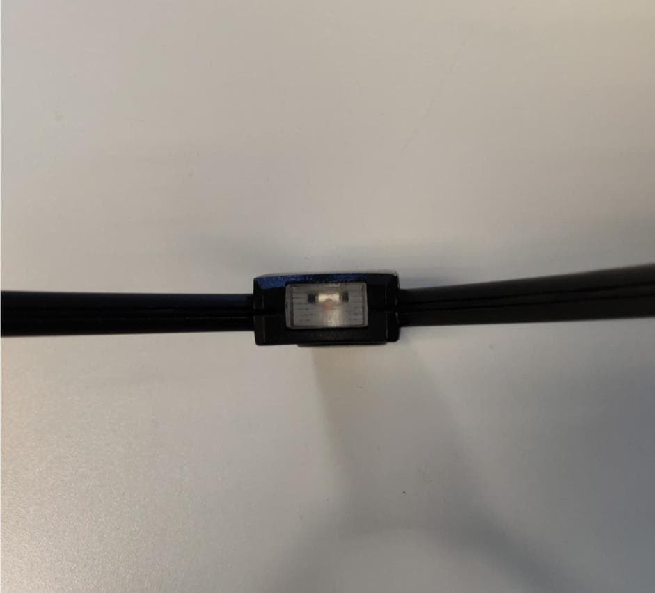
Click to zoom
Application Details
- Equipment Class
- DSS - Part 15 Spread Spectrum Transmitter
- Date of Grant
- Jul 14, 2020
- Application Purpose
- Original Equipment
- Date of Application
- Jul 14, 2020
- Equipment Note
- Real ear measurement system + Audiometer
- Frequency Range
- 2402.00000000 - 2480.00000000
- Company
- Inventis SRL
- Country
- Italy
Documents & Files
Document Text
Text extracted from the exhibit documents filed with the FCC. Open a document above to read the original.
Users Manual
TRUMPET REAL EAR MEASUREMENTS SYSTEM AUDIOMETER USER MANUAL ii iii Read this manual carefully before using the instrument. Pay particular attention to the instructions given in Chapter 1 (“Safety: warnings and information”) and in Chapter 3 (“Installation”). Internal inspection and servicing of the instrument must be entrusted entirely to technicians approved by Inventis S.r.l. Copyright: Inventis S.r.l. is the owner of the copyright on this manual. It is forbidden to copy, reproduce or alter the manual, in its entirety or in part, without the express written authorization of Inventis S.r.l.. Inventis ® is a registered trademark owned by Inventis S.r.l.. Inventis S.r.l. Corso Stati Uniti, 1/3 35127 Padova, Italia Tel.: 049.8962844 Fax: 049.8966343 www.inventis.it [email protected] Revision: 17 Date: 24/06/2020 v Summary Summary ....................................................................................v CHAPTER 1 Safety: warnings and information ................... 1 1.1 User Manual ............................................................ 1 1.2 Operator responsibilities ........................................ 1 1.3 Intended use of the device ...................................... 2 1.4 Indication for use and end users of the device...... 2 1.5 Precautions .............................................................. 3 1.6 Disposal .................................................................... 6 1.7 Conformity ............................................................... 7 1.8 FCC/ISED use restrictions and warnings ............. 7 1.9 Symbols on labels .................................................... 9 CHAPTER 2 Introduction .................................................... 11 2.1 Description of the product .................................... 11 2.2 Accessories ............................................................. 13 2.3 Preparation for an REM test ............................... 19 CHAPTER 3 Installation ...................................................... 31 3.1 Connections............................................................ 31 CHAPTER 4 Maintenance ................................................... 39 4.1 Calibration and equalization (REM)................... 39 4.2 Periodic checks ...................................................... 40 4.3 Cleaning and maintenance of transducers.......... 40 vi 4.4 Replaceable parts .................................................. 41 4.5 Repairs and technical assistance .......................... 42 4.6 Enable new licenses ............................................... 42 4.7 Firmware upgrade ................................................ 43 4.8 Calibration of microphones by code.................... 43 APPENDIX A: Technical Specifications ............................. 45 REM specifications ................................................................ 45 Audiometer specifications ...................................................... 47 Other specifications ................................................................ 53 APPENDIX B: Specifications of speaker for free field tests ................................................................................................. 59 APPENDIX C: Troubleshooting .......................................... 61 APPENDIX D: Electromagnetic emissions ......................... 65 1 CHAPTER 1 Safety: warnings and information 1.1 USER MANUAL Be sure to read this manual through completely, so that all of the features offered by the Trumpet instrument can be used to their full potential. In particular, be sure to read this chapter in its entirety, as it contains information and warnings that are of fundamental importance in ensuring safe and correct use of the device. The safety warning symbol illustrated below is used in this manual to draw the attention of the reader to information of particular importance in matters of safety, and to guard against incorrect use. 1.2 OPERATOR RESPONSIBILITIES The Trumpet device guarantees consistent and dependable performance only when used in accordance with the instructions and procedures described in this manual. In the event of the device malfunctioning and needing to undergo repair or maintenance work, it must be disconnected from the electrical power supply, and not used again until after this work has been completed. When defective or failed parts must be renewed, accept only original replacement parts supplied by Inventis s.r.l. Any repairs must be entrusted exclusively to Inventis or to service technicians approved by Inventis. No parts of the device must be modified or replaced without authorization from Inventis. 2 The user of the device assumes full responsibility for any malfunction resulting from improper use or operation, likewise from maintenance or repair work performed by third parties other than Inventis s.r.l. or Service Centres approved by Inventis. Inventis s.r.l. and approved Service Centres will answer for the performance and reliability of the equipment only if: 1. adjustments, modifications or repairs have been entrusted to persons authorized by Inventis; 2. the electrical system and earthing of the installation are in compliance with the specifications of standards for electro-medical appliances. 1.3 INTENDED USE OF THE DEVICE Trumpet is a real ear measurement system. A real ear measurement system allows the determination of the intensity of sounds reaching the tympanic membrane of the patient. To this end it uses a couple of microphones, one located at the level of the patient’s earlobe (the reference microphone), and one inserted in the patient ear canal through a silicon tube (the probe microphone). The operator, using the system, delivers to the patient sound stimuli different in intensity and in frequency content, and measures the intensity of the sound received by the two microphones. A real ear measurement system is generally used to quantify the gain provided by a hearing aid, when this is …
Text truncated - open the document above for the full version.
Cover Letter(s)
Inventis srl Corso Stati Uniti 1/3 35127 Padova (PD), Italy Equipment Autorisation Division Federal Communications Commission 7435 Oakland Mills Road Columbia, MD 21046 FCC ID: 2AVOO-RE1RAWP Product Name: Real ear measurement system + Audiometer Request for Confidentiality Pursuant to Sections 0.457(d) and 0.459 of the commissions rules, we hereby request that the following documents be held confidential: • Schematics • Block diagrams • Operation Description • Part list These materials contain trade secrets and proprietary information and are not customarily released to the public. The public disclosure of this information might be harmful to the company and provide unjustified benefits to our competitors.
Cover Letter(s)
Inventis srl Corso Stati Uniti 1/3 35127 Padova (PD), Italy Nemko Canada Inc 303 River Road Ottawa, Ontario, Canada K1V 1H2 Attn: Director of Certification Authority to Act as Agent On our behalf, I appoint Nemko Canada Inc. to act as our agent in the preparation of this application for equipment certification. I certify that submitted documents properly describe the device or system for which equipment certification is sought. I also certify that each unit manufactured, imported or marketed, as defined in Industry Canada’s regulations will have affixed to it a lab identical to that submitted for approval with this application. For instances where our authorized agent signs the application for certification on our behalf, I acknowledge that all responsibility for complying with the terms and conditions for certification, as specified by Nemko Canada Inc, still resides with Inventis srl, Corso Stati Uniti 1/3, 35127 Padova (PD), Italy. Dated this 12 Day of June 20 20 Agency agreement expiration date: 27 April 2021 By: Massimo Martinelli Signature Printed Title: Managing Director On behalf of : Inventis SRL Telephone: +39 347 7045497
External Photos
INVENTIS S.R.L. CORSO STATI UNITI, 1/3 35127 PADOVA - ITALIA TEL: +39 049.8962 844 FAX: +39 049.8966 343 C.F./P.IVA:IT03957810280 R.E.A. PD 350789 [email protected] WWW.INVENTIS.IT EXTERNAL PHOTOS WPROBE FCC ID: 2AVOO-RE1RAWP IC: 25857-RE1RAWP Wireless probe – front INVENTIS S.R.L. CORSO STATI UNITI, 1/3 35127 PADOVA - ITALIA TEL: +39 049.8962 844 FAX: +39 049.8966 343 C.F./P.IVA:IT03957810280 R.E.A. PD 350789 [email protected] WWW.INVENTIS.IT Wireless probe – back INVENTIS S.R.L. CORSO STATI UNITI, 1/3 35127 PADOVA - ITALIA TEL: +39 049.8962 844 FAX: +39 049.8966 343 C.F./P.IVA:IT03957810280 R.E.A. PD 350789 [email protected] WWW.INVENTIS.IT Wireless probe – top
ID Label/Location Info
INVENTIS S.R.L. CORSO STATI UNITI, 1/3 35127 PADOVA - ITALIA TEL: +39 049.8962 844 FAX: +39 049.8966 343 C.F./P.IVA:IT03957810280 R.E.A. PD 350789 [email protected] WWW.INVENTIS.IT WPROBE FCC ID: 2AVOO-RE1RAWP IC: 25857-RE1RAWP Serial number Label: RE1-LA003_REV01 FCC-IC ID Label: RE1-LA037_REV01 INVENTIS S.R.L. CORSO STATI UNITI, 1/3 35127 PADOVA - ITALIA TEL: +39 049.8962 844 FAX: +39 049.8966 343 C.F./P.IVA:IT03957810280 R.E.A. PD 350789 [email protected] WWW.INVENTIS.IT Wireless probe label positioning
Internal Photos
INVENTIS S.R.L. CORSO STATI UNITI, 1/3 35127 PADOVA - ITALIA TEL: +39 049.8962 844 FAX: +39 049.8966 343 C.F./P.IVA:IT03957810280 R.E.A. PD 350789 [email protected] WWW.INVENTIS.IT INTERNAL PHOTOS WPROBE FCC ID: 2AVOO-RE1RAWP IC: 25857-RE1RAWP Wireless probe front shell with batteries Wireless probe front shell without batteries INVENTIS S.R.L. CORSO STATI UNITI, 1/3 35127 PADOVA - ITALIA TEL: +39 049.8962 844 FAX: +39 049.8966 343 C.F./P.IVA:IT03957810280 R.E.A. PD 350789 [email protected] WWW.INVENTIS.IT RE1-EL007 board – top view INVENTIS S.R.L. CORSO STATI UNITI, 1/3 35127 PADOVA - ITALIA TEL: +39 049.8962 844 FAX: +39 049.8966 343 C.F./P.IVA:IT03957810280 R.E.A. PD 350789 [email protected] WWW.INVENTIS.IT RE1-EL007 board – bottom view RE1-EL009 board – bottom view (for components reference, please refer to the appendix) INVENTIS S.R.L. CORSO STATI UNITI, 1/3 35127 PADOVA - ITALIA TEL: +39 049.8962 844 FAX: +39 049.8966 343 C.F./P.IVA:IT03957810280 R.E.A. PD 350789 [email protected] WWW.INVENTIS.IT Wireless probe back shell with board protection Wireless probe back shell without protection Wireless probe back shell with RE1-EL006 board and coil INVENTIS S.R.L. CORSO STATI UNITI, 1/3 35127 PADOVA - ITALIA TEL: +39 049.8962 844 FAX: +39 049.8966 343 C.F./P.IVA:IT03957810280 R.E.A. PD 350789 [email protected] WWW.INVENTIS.IT RE1-EL006 board – top view with battery pins soldered RE1-EL006 board – bottom view with coil soldered Appendix
Operational Description
2450 MHz AntennaP/N 2450AT18B100 Detail Specification: 08/10/09 Page 1 of 3 General Specifications Part Number 2450AT18B100 Input Power 3W max. Frequency Range 2400 - 2500 Mhz Impedance 50 Ω Peak Gain 0.5 dBi typ. (XZ-V) Operating Temperature -40 to +85°C Average Gain -0.5 dBi typ. (XZ-V) Reel Quanity 3,000 Return Loss 9.5 dB min. Terminal Configuration Packaging BulkSuffix = SEg. 2450AT18B100S No. Function P/N Style T & RSuffix = EEg. 2450AT18B100E 1 Feeding Point Suffix Termination 100% TinSuffix = None Eg. 2450AT18B100(E or S) 2 NC Style Tin / Lead Mechanical Dimensions Inmm L ±± W ±± T a ±± Mounting Considerations Mount these devices with brown mark facing up. Units: mm Line width should be designed to provide 50 Ω impedance matching characteristics. a) Without Matching Circuits b) With Matching Circuits Johanson Technology, Inc. reserves the right to make design changes without notice. All sales are subject to Johanson Technology, Inc. terms and conditions. www.johansontechnology.com 4001 Calle Tecate • Camarillo, CA 93012 • TEL 805.389.1166 FAX 805.389.1821 2009 Johanson Technology, Inc. All Rights Reserved Please consult Factory 0.0120.020 1.30 0.30 1.600.200.008 0.051 +.004/-.008+0.1/-0.2 "High Frequency Ceramic Solutions" 0.50 0.1260.0083.200.20 0.063 1 2 L W a T ) Matching Component JTI P/Ns: L-14C2N7JV4 L-14C2N2JV4 * 2.6 4.2 1.6 1.9 0.4 2.7nH 1.2pF 3.3nH JTI P/N for Matching Circuit: Cap (1.2pF): 500R07S1R2BV4T Inductor (2.7nH): L-07C2N7SV6T Inductor (3.3nH): L-07C3N3SV6T 2450 MHz AntennaP/N 2450AT18B100 Detail Specification: 08/10/09 Page 2 of 3 Typical Electrical Characteristics (T=25 o C) Test Board: Return Loss a) Without Matching Circuitb) With Matching Circuit Johanson Technology, Inc. reserves the right to make design changes without notice. All sales are subject to Johanson Technology, Inc. terms and conditions. www.johansontechnology.com 4001 Calle Tecate • Camarillo, CA 93012 • TEL 805.389.1166 FAX 805.389.1821 2009 Johanson Technology, Inc. All Rights Reserved "High Frequency Ceramic Solutions" ) ) ) ) ) ) ) ) ) Ground 13.5mm 6.5mm 39.5mm 6.5mm Matching Circuit No Ground 50Ω Feed Line Antenna 19mm 4mm 2450 MHz AntennaP/N 2450AT18B100 Detail Specification: 08/10/09 Page 3 of 3 Typical Radiation Patterns Johanson Technology, Inc. reserves the right to make design changes without notice. All sales are subject to Johanson Technology, Inc. terms and conditions. www.johansontechnology.com 4001 Calle Tecate • Camarillo, CA 93012 • TEL 805.389.1166 FAX 805.389.1821 2009 Johanson Technology, Inc. All Rights Reserved "High Frequency Ceramic Solutions" ) ) ) ) ) ) ) ) ) Mouser Electronics Authorized Distributor Click to View Pricing, Inventory, Delivery & Lifecycle Information: Johanson: 2450AT18B100E
Operational Description
Qualcomm Technologies International, Ltd. Confidential and Proprieta ry – Qualcomm Technologies Intern ational, Ltd. (formerly known as Cambridge Silicon Radio Ltd.) NO PUBLIC DISCLOSURE PERMITTED: P lease report p ostings of t his document on public s ervers or websites to: [email protected]. Restricted Distribution: Not to be distributed to anyone who is not an employee of either Qualcomm Tec hnologies International, Ltd.or its affiliated companies without t he express approval of Q ualcomm Conf iguration Management. Not to be used, copied, reproduced, or modified in whole or in part, nor its contents revealed in any manner to others without the express written permission of Q ualcomm Technologies International, Ltd. Any software provided with this notice is governed by the Qualcomm Technologies International, Ltd. Terms of Supply or the applicable license agreement at https://www.csrsupport.com/CSRTermsandConditions. Qualcomm is a trademark of Qualcomm Incorporat ed, registered in the United States and other count ries. All Qualcomm I ncorporated trademarks are used with permission. Other product and brand names may be trademarks or registered trademarks of their respective owners. This t ec hnical data may be s ubject to U.S. and international export, re-export, or transfer (“export”) laws. Diversion contrary to U.S. and international law is strictly p rohibited. © 2015 Qualcomm Technologies International, Ltd. A ll r ights res erved. Qualcomm Technologies Int ernational, Ltd. Churchill House Cambridge Business Park Cambridge, CB4 0WZ United Kingdom BlueCore ® ႑ Bluetooth ® v4.1 specification fully qualified ႑ Radio includes integrated balun ႑ 80 MHz RISC MC≥ and 120 MHz Kalimba DSP ႑ ≥p to 120 MIPS DSP for intensive digital signal processing algorithms ႑ 24-bit audio ႑ 16 Mb internal flash; optional support for 64 Mb of external SPI flash ႑ Stereo codec with 2 channels of ADC and up to 6 microphone inputs (includes bias generation and digital microphone support) ႑ Audio interfaces: ႑ 2 x I²S/PCM ႑ 1 x SPDIF (independent of I²S/PCM ports) ႑ Serial interfaces: ≥AR≤, ≥SB 2.0 full-speed, I²C and SPI ႑ Integrated dual switch-mode regulators, linear regulators and battery charger ႑ 3 hardware LED controllers (for RGB) and ability to drive LCD segment display directly ႑ Support for up to 6 capacitive touch sensor inputs ႑ 6.5 x 6.5 x 1 mm, 0.5 mm pitch 112ತball VFBGA ႑ CSR8675 BGA application boards backward compatible with CSR8670 BGA ႑ Green (RoHS compliant and no antimony or halogenated flame retardants) Low-power Solution for CSR8675 BGA consumer audio platform for wired and wireless applications integrates an ultraತlowತpower DSP and application processor with embedded flash memory, a high-performance stereo codec, a power management subsystem, LED and LCD drivers and capacitive touch sensor inputs in a SoC IC. 2.4 GHz Radio + Balun I/O B≤_RFRAM Baseband MC≥ Kalimba DSP Flash X≤AL Serial Flash External Memory ≥AR≤/≥SB PIO Audio In /Out PCM/I 2 S SPI/I 2 C LED /PIO Audio Interface Capacitive Sense Clock Generation SPDIF PCM/I 2 S ႑ High-end wired/wireless stereo headphones ႑ High-end wired/wireless stereo headsets ႑ High-end wired/wireless active headsets ႑ Wireless stereo speakers ႑ Low-end docking stations and soundbars ႑ Gaming headsets ≤he dual-core architecture with flash memory enables manufacturers to easily differentiate their products with new features without extending development cycles. ≤he enhanced Kalimba DSP coprocessor with up to 120 MIPS supports more digital signal processing requirements in stereo headphones, headsets, gaming headsets and soundbars. ≤he audio codec supports 2 ADC channels, up to 6 microphone inputs, stereo output and a variety of audio standards. CSR's popular BlueCore ® CSR8670 റ and BlueCore ® 5ತMultimedia platforms are softwareತportable to the CSR8675 BGA, with easy migration of a broad range of solutions from CSR's eXtension partners. ≤his enables rapid time-to-market deployment for a broad range of consumer electronic products. Production Information © Cambridge Silicon Radio Limited 2013-2015 Confidential Information - ≤his Material is Subject to CSR's Non-Disclosure Agreement Page 1 of 112 CS-232426-DSP7 www.csr.com CSR8675 BGA Data Sheet Prepared for customer=Jesper Christensen - sonosound.eu - 20-Jun-2017 CSR8675 VFBGAತ112ತball (Pb free) 6.5 x 6.5 x 1 mm 0.5 mm pitch ≤ape and reelCSR8675CತIBBHತR Minimum order quantity is 2kpcs taped and reeled. : CSR's manufacturing policy is to multisource volume products. For further details, contact your local sales account manager or representative. General information Information on this product Customer support for this product Details of compliance and standards Help with this document www.csr.com [email protected] www.csrsupport.com [email protected] [email protected] CSR8675 BGA Audio Development Kit forDK-CSR8675-10197-2A CSR8675 BGA Development Kit (Board Only)DB-CSR8675-10200-2A Production Information © Cambridge Silicon Radio Limited 2013-2015 Confidential Information - ≤his Material is Subject to CSR's Non-Disclosure Agreement Page 2 of 112 CS-232426-DSP7 www.csr.com CSR8675 BGA Data Sheet Prepared for customer=Jesper Christensen - sonosound.eu - 20-Jun-2017 ႑Dualತmode Bluetooth low energy radio ႑Support for Bluetooth basic rate / EDR and low energy connections ႑3 Bluetooth low energy connections at the same time as basic rate A2DP ႑Onತchip balun (50 ˖ impedance in ≤X and RX modes) ႑No external trimming is required in production ႑Bluetooth v4.1 specification software/hardware ႑≤ypical RF transmit power ႑Basic rate 10 dBm ႑EDR -1 dB (relative power) ႑Bluetooth low energy 9 dBm ႑6ತbit DAC level control ႑Class 1, Class 2 and Class 3 support without the need for an external power amplifier or ≤X/RX switch ႑≤ypical RF receiver sensitivity: ႑Basic rate -90 dBm ႑EDR -92 dBm ႑Bluetooth low energy -93 dBm ႑Integrated channel filters ႑Digital demodulator for improved sensitivity and coತchan…
Text truncated - open the document above for the full version.
Operational Description
INVENTIS S.R.L. CORSO STATI UNITI, 1/3 35127 PADOVA - ITALIA TEL: +39 049.8962 844 FAX: +39 049.8966 343 C.F./P.IVA:IT03957810280 R.E.A. PD 350789 [email protected] WWW.INVENTIS.IT OPERATIONAL DESCRIPTION WPROBE FCC ID: 2AVOO-RE1RAWP IC: 25857-RE1RAWP INVENTIS S.R.L. CORSO STATI UNITI, 1/3 35127 PADOVA - ITALIA TEL: +39 049.8962 844 FAX: +39 049.8966 343 C.F./P.IVA:IT03957810280 R.E.A. PD 350789 [email protected] WWW.INVENTIS.IT General description WPROBE is the wireless transduction probe of the “Real ear measurement system + Audiometer” system. This device uses a Bluetooth interface to stream audio signals from the 4 microphones mounted on the probe itself. The two stereo audio streams are then analysed by the main unit in order to calculate the FFT curves. The device uses also a wireless power charging receiver for the charging. Technical details The RE1-EL007 board of the wireless probe contains a BlueCore® CSR8675 BGA, made by Qualcomm. This integrated single-chip solution is used for wireless audio applications, and integrates a dual mode Bluetooth radio, a low power DSP, an application processor, a battery charger, memory and various audio and hardware interfaces. The frequency of the local oscillator of the CSR8675 BGA chipset is 26 MHz. For additional information about the CSR8675 BGA chipset, see the datasheet CSR8675 CS-232426-DS-7.pdf, or contact Qualcomm directly. The CSR8675 BGA RF output is connected to a 2.4GHz Band Pass Filter (p/n: 2450BP14D0100), followed by a 2.4 GHz Mini Antenna (p/n: 2450AT18B100), both made by Johanson Technology: INVENTIS S.R.L. CORSO STATI UNITI, 1/3 35127 PADOVA - ITALIA TEL: +39 049.8962 844 FAX: +39 049.8966 343 C.F./P.IVA:IT03957810280 R.E.A. PD 350789 [email protected] WWW.INVENTIS.IT The pass-band filter has been made considering the following design specifications: INVENTIS S.R.L. CORSO STATI UNITI, 1/3 35127 PADOVA - ITALIA TEL: +39 049.8962 844 FAX: +39 049.8966 343 C.F./P.IVA:IT03957810280 R.E.A. PD 350789 [email protected] WWW.INVENTIS.IT Furthermore, for the 2.4 GHz Mini Antenna (p/n: 2450AT18B100) matching and grounding: INVENTIS S.R.L. CORSO STATI UNITI, 1/3 35127 PADOVA - ITALIA TEL: +39 049.8962 844 FAX: +39 049.8966 343 C.F./P.IVA:IT03957810280 R.E.A. PD 350789 [email protected] WWW.INVENTIS.IT Wireless charging interface The RE1-EL007 board of the wireless probe contains also a reader for the device wireless charging. The receiver chip is a Texas Instrument bq51010B, an integrated wireless power supply receiver with a 7V regulated supply. The chipset bq51010B has not a local oscillator. Remark: during the WPROBE recharging, the wireless interface operates at 142,3 kHz, with a maximum power transfer of 2.1 W. The receiver bq51010B is physically placed in the RE1-EL007 board: INVENTIS S.R.L. CORSO STATI UNITI, 1/3 35127 PADOVA - ITALIA TEL: +39 049.8962 844 FAX: +39 049.8966 343 C.F./P.IVA:IT03957810280 R.E.A. PD 350789 [email protected] WWW.INVENTIS.IT The QI charge receiver coil is soldered to a dedicated PCB (RE1-EL006), placed on the back shell of the Wireless probe, and it is connected to the RE1-EL007 board through two pins, put in direct contact when the two shells of the probe are closed: Connection pins INVENTIS S.R.L. CORSO STATI UNITI, 1/3 35127 PADOVA - ITALIA TEL: +39 049.8962 844 FAX: +39 049.8966 343 C.F./P.IVA:IT03957810280 R.E.A. PD 350789 [email protected] WWW.INVENTIS.IT Connection pins RE1-EL007 board
RF Exposure Info
ONE WORLD OUR APPROVAL www.nemko.com KDB 447498 D01 General RF Exposure Guidance v06 (October 23, 2015) 1. Declaration of RF exposure compliance for exemption from routine evaluation limits FCC ID: 2AVOO-RE1RAWP Model number: WPROBE Manufacturer: Inventis Srl 4.3.1. Standalone SAR test exclusion considerations: During normal operation, user extremities can come within 20 cm of the internal antenna and therefore product is considered as “Portable”. The 1-g and 10-g SAR test exclusion thresholds for 100 MHz to 6 GHz at Test separation distances ≤ 50 mm are determined by: [(max. power of channel, including tune-up tolerance, mW) ÷ (min. test separation distance, mm)] × [ √ 퐹(퐺퐻푧)] ≤ 3.0 for 1-g SAR, and ≤ 7.5 for 10-g extremity SAR, where • F(GHz) is the RF channel transmit frequency in GHz • Power and distance are rounded to the nearest mW and mm before calculation • The result is rounded to one decimal place for comparison The test exclusions are applicable only when the minimum test separation distance is ≤ 50 mm, and for transmission frequencies between 100 MHz and 6 GHz. When the minimum test separation distance is < 5 mm, a distance of 5 mm according to section 4.1(f) is applied to determine SAR test exclusion Calculation based on the above formula: Separation Distance = 5 mm Conducted Output Power = (-2.5) dBm = 0.57 mW Frequency = 2.480 GHz Calculation = (0.57÷5)× √ 2.480 = 0,18 ≤ 3.0 The calculation is below the threshold, therefore the product exempt from the SAR test requirements 2. Attestation ATTESTATION: I attest that the testing was performed or supervised by me; that the test measurements were made in accordance with the above-mentioned departmental standard(s), and that the radio equipment identified in this application has been subject to all applicable test conditions specified in the departmental standards and all of the requirements of the standards have been met. Signature: Date: March 19, 2020 Name: Paolo Barbieri FCC SAR Exemption per KDB 447498
Test Report
Report reference ID: 381371-5TRFWL Page 1 of 136 This test report may not be partially reproduced, except with the prior written permission of Nemko Spa The test report merely corresponds to the tested sample. The phase of sampling / collection of equipment under test is carried out by the customer. Test location ONE WORLDOURAPPROVAL Test report 381371-5TRFWL Date of issue: 2020-03-19 Applicant: Inventis SRL Corso Stati Uniti, 1/3 – 35127 Padova (PD) – Italia Product: WPROBE Model: WPROBE FCC ID: IC Registration number: 2AVOO-RE1RAWP 25857-RE1RAWP Specifications: FCC 47 CFR Part 15 Subpart C, §15.247 Operation in the 902–928 MHz, 2400–2483.5 MHz, and 5725–5850 MHz RSS-247, Issue 2, Feb 2017, Section 5 Digital Transmission Systems (DTSs), Frequency Hopping Systems (FHSs) and Licence-Exempt Local Area Network (LE-LAN) Devices. Standard specifications for frequency hopping systems and digital transmission systems operating in the bands 902–928 MHz, 2400–2483.5 MHz and 5725–5850 MHz Report reference ID: 381371-5TRFWL Page 2 of 136 Company name: Nemko Spa Address: Via del Carroccio, 4 City: Biassono Province: MB Postal code: 20853 Country: Italy Telephone: +39 039 220 12 01 Facsimile: +39 039 220 12 21 Website: www.nemko.com Site number: FCC: 682159; IC: 9109A (10 m semi anechoic chamber) Tested by (name, function and signature) P. Barbieri (project handler) Reviewed by (name, function and signature) D. Guarnone (verifier) Date: 2020-03-19 Limits of responsibility Note that the results contained in this report relate only to the items tested and were obtained in the period between the date of initial receipt of samples and the date of issue of the report. This test report has been completed in accordance with the requirements of ISO/IEC 17025. All results contain in this report are within Nemko Spa ISO/IEC 17025 accreditation. Copyright notification Nemko Spa authorizes the applicant to reproduce this report provided it is reproduced in its entirety and for use by the company’s employees only. Any use which a third party makes of this report, or any reliance on or decisions to be made based on it, are the responsibility of such third parties. Nemko Spa accepts no responsibility for damages, if any, suffered by any third party as a result of decisions made or actions based on this report. Report reference ID: 381371-5TRFWL Page 3 of 136 Table of contents Table of contents .......................................................................................................................................................................................................... 3 Section 1. Report summary ................................................................................................................................................................................. 4 1.1 Applicant and manufacturer .................................................................................................................................................................................... 4 1.2 Test specifications .................................................................................................................................................................................................... 4 1.3 Test methods ............................................................................................................................................................................................................ 4 1.4 Statement of compliance ......................................................................................................................................................................................... 4 1.5 Exclusions ................................................................................................................................................................................................................. 4 1.6 Test report revision history ...................................................................................................................................................................................... 4 Section 2. Summary of test results ....................................................................................................................................................................... 5 2.1 FCC Part 15 Subpart C, general requirements test results ........................................................................................................................................ 5 2.2 FCC Part 15 Subpart C, intentional radiators test results.......................................................................................................................................... 5 2.3 ISED RSS-GEN, Issue 5, test results ........................................................................................................................................................................... 5 2.4 ISED RSS-247, Issue 2, test results ............................................................................................................................................................................ 6 Section 3. Equipment under test (EUT) details .................................................................................…
Text truncated - open the document above for the full version.
Contact Information
Applicant
Massimo Martinelli(Managing Director)
Test Firm
Nemko S.p.A.Roberto Giampaglia
Technical Specifications
| # | Rule Parts | Frequency Range | Power Output |
|---|---|---|---|
| 1 | 15C | 2.40 GHz - 2.48 GHz | 570.00 µW |
Other Applications from Inventis SRL
2AVOO-RE1RA
Jul 21, 2020Real ear measurement system+Audiometer
Equipment Class
DCD - Part 15 Low Power Transmitter Below 1705 kHz