2AVOQ02Flight Instrument For Paragliding / Hang Gliding
XC Tracer GmbH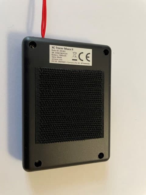
Click to zoom
Application Details
- Equipment Class
- DTS - Digital Transmission System
- Date of Grant
- Jul 05, 2023
- Application Purpose
- Original Equipment
- Date of Application
- Jul 05, 2023
- Equipment Note
- Flight Instrument For Paragliding / Hang Gliding
- Frequency Range
- 903.00000000 - 927.00000000
- Company
- XC Tracer GmbH
- Country
- Switzerland
Documents & Files
Document Text
Text extracted from the exhibit documents filed with the FCC. Open a document above to read the original.
Users Manual
Instruction Manual XC Tracer Maxx II Rev 02 4.07.2023 Instruction Manual XC Tracer Maxx II Instruction Manual XC Tracer Maxx II Rev 02 4.07.2023 Brief instructions Fix the vario on the cockpit or on your thigh. Press the red button and wait until beep-beep, then release the button. At first only the logo appears, after a few seconds the preset screen appears. As long as the vario is searching for GPS satellites, the word GPS will flash in the upper right corner. As soon as a GPS fix is available, the battery symbol is displayed and you can start. You can change the screen by a short push on the button. You can change the volume level by double- clicking on the button. After landing, switch the vario off by pressing the button until you hear beep- beep, then release the button. If you want to change the settings: press the button twice in quick succession and hold it down for a second on the second click. To get to the desired setting press the button once briefly; with a long press select/change the setting. The vario is preset to beep only when flying. But you can set this as you wish. If you want to download the tracks or change the configuration file then connect XC Tracer Maxx II to your computer with the included USB-C cable. Now switch on the vario and the SD card of XC Tracer Maxx II will appear on the computer as a USB hard drive. Now you can download tracks, change settings in the config file, or copy new firmware updates to the SD card. The new firmware is installed as soon as you switch off the vario. Important: Before disconnecting from the computer, please always eject the SD card on the computer. WARNING: Charge the battery with the USB cable on the PC or on a 5V charger. Only a 5V connection / charger may be used, do not use Fast Charge / Quick Charge / Super Charge / Turbo Power or whatever. If a voltage higher than 5V is used while charging, the electronics will be destroyed. Never use a cheap charger; this can damage your XC Tracer Maxx II. We accept no responsibility for damage which occurs when not using the correct voltage for charging! Instruction Manual XC Tracer Maxx II Rev 02 4.07.2023 Introduction XC Tracer Maxx II is a high-precision GPS variometer with a perfectly readable LCD and integrated collision warning using FLARM. XC Tracer Maxx II transmits its position once per second and also the estimated flight path for the next 20 seconds. Other FLARM devices in the vicinity can then draw conclusions about a possible risk of collision. In case of a possible collision the corresponding FLARM device warns the pilot of the other aircraft. XC Tracer Maxx II itself does not warn you of possible collisions with other aircraft. Many pilots use XC Tracer flight instruments for long XC flights and for competitions. But also for pilots with little flying experience an XC Tracer Variometer is the perfect choice. The lag-free indication of lift / sink rate makes it much easier to find and core thermals than when using a conventional variometer. All essential flight information is displayed on the LCD. XC Tracer Maxx II is also an IGC logger – the IGC files are approved by the FAI for paragliding competitions. XC Tracer Maxx II has a built-in lithium-polymer battery, fully charged the battery is good for at least 60 hours of continuous operation. The battery is charged via the supplied USB-C cable. The device also has a Bluetooth module. Using Bluetooth Low Energy 4.2, data such as airspeed, altitude, climb, course etc. can be transferred to a mobile phone, tablet or e-reader. Please check xctracer.com to see which apps need to be configured with which BLE strings. Mounting XC Tracer Maxx II uses data from a 9-DOF IMU (9 Degrees Of Freedom Inertial Measurement Unit), from the GPS and from a pressure sensor, to compute the real-time climb rate and altitude, avoiding the undesired time lag that conventional variometers suffer from (due to data filtering). For this reason mount your XC Tracer Maxx II in such a way that it moves as little as possible in relation to the harness during flight. It is therefore important that the XC Tracer Maxx II is firmly attached to the cockpit or thigh with the velcro provided. Mounting on the riser is not ideal. Important – leave 4-5cm free space around your vario; otherwise the performance of the FLARM / FANET beacon may be compromised. Switch On/Switch Off The XC Tracer Maxx II is switched on by pressing the red button until a "beep-beep" is heard. Then release the button and the XC Tracer Maxx II will start up. After switching on, the battery charge level is indicated acoustically. At first only the logo appears, after a few seconds the preset screen appears. As long as the vario is searching for GPS satellites, the word GPS flashes in the upper right corner. As soon as there is a GPS fix, this lettering disappears and the battery symbol is displayed. Now you can start. You can change the screen by a short push on the button. You can change the volume by double clicking on it. After landing, switch off the vario by pressing the button until you hear a beep-beep and the vario is switched off. Instruction Manual XC Tracer Maxx II Rev 02 4.07.2023 Battery Indicator After switching the device on the battery charge status is indicated with a sequence of short beeps: 5x Beep means that the battery is charged 95% or more. 4x Beep means that the battery is charged 75% or more. 3x Beep means that the battery is charged 55% or more. 2x Beep means that the battery is charged 35% or more. 1x Beep means that the battery is charged 15% or more. When the battery is less than 15% charged you will hear a constant beep for one second after switching the device on. The battery charge level is also displayed on the LCD. Adjusting The Volume XC Tracer Maxx II has 4 volume settings: Mute, very gentle, gentle, medium and loud. You can change the volume level by double pressing the red button (like a double click on the mouse of your computer), always from mute – ve…
Text truncated - open the document above for the full version.
External Photos
FCC ID: 2AVOQ02 FCC ID: 2AVOQ02 FCC ID: 2AVOQ02 FCC ID: 2AVOQ02 FCC ID: 2AVOQ02 FCC ID: 2AVOQ02
Internal Photos
FCC ID: 2AVOQ02 G0M-2210-1716 FCC ID: 2AVOQ02 G0M-2210-1716 FCC ID: 2AVOQ02 G0M-2210-1716 FCC ID: 2AVOQ02 G0M-2210-1716 Module with FCC ID: XPYANNAB1 FCC ID: 2AVOQ02 G0M-2210-1716 FCC ID: 2AVOQ02 G0M-2210-1716 LoRA RF chip
RF Exposure Info
Test Report No.: G0M-2210-1716-TFC091MP-V02 Eurofins Product Service GmbH Storkower Str. 38c, D-15526 Reichenwalde, Germany Page 1 of 15 RF-EXPOSURE REPORT FCC 47 CFR Part 2.1091 Maximum permissible exposure Report Reference No G0M-2210-1716-TFC091MP-V02 Testing Laboratory Eurofins Product Service GmbH Address Storkower Str. 38c 15526 Reichenwalde Germany Accreditation A2LA Accredited Testing Laboratory, Certificate No.: 1983.01 FCC Test Firm Designation Number: DE0008 Applicant XC Tracer GmbH Address Junkerngasse 53 3011 Bern SWITZERLAND Test Specification According to FCC rules Standard FCC 47 CFR 2.1091 Non-Standard Test Method None Equipment under Test (EUT): Product Description Flight Instrument Model(s) XC Tracer Maxx II Additional Model(s) None Brand Name(s) None Hardware Version(s) XC_Tracer_Maxx_II_R03 Software Version(s) 20220511_0_9_16_FCC FCC-ID 2AVOQ02 Test Result PASSED Test Report No.: G0M-2210-1716-TFC091MP-V02 Eurofins Product Service GmbH Storkower Str. 38c, D-15526 Reichenwalde, Germany Page 3 of 15 VERSION HISTORY Version History Version Issue Date Remarks Revised By 01 2023-03-01 Initial Release R. Jaafar 02 2023-06-12 Replaced document: G0M-2210-1716-TFC091MP-V01 Replaced by: G0M-2210-1716-TFC091MP-V02 Reason: - Correction of Reference document no. 21CH-01312.R12 to 21CH-01312.R22 - Correction of the antenna gain according to the document “Declaration concerning Anntenna Specification_2023-03- 23” issued by XC Tracer GmbH on 2023-03-23. Test Report No.: G0M-2210-1716-TFC091MP-V02 Eurofins Product Service GmbH Storkower Str. 38c, D-15526 Reichenwalde, Germany Page 4 of 15 ABBREVIATIONS AND ACRONYMS Acronyms Acronym Description EIRP Equivalent Isotropic Radiated Power EUT Equipment Under Test MPE Maximum Permissible Exposure Test Report No.: G0M-2210-1716-TFC091MP-V02 Eurofins Product Service GmbH Storkower Str. 38c, D-15526 Reichenwalde, Germany Page 5 of 15 REPORT INDEX 1 Equipment (Test Item) Under Test................................................................................................... 6 1.1 Reference Documents ................................................................................................................................... 7 1.2 Power density radiation sources.................................................................................................................... 8 1.3 Field strength radiation sources .................................................................................................................... 8 1.4 Concurrent Sources ...................................................................................................................................... 8 2 Result Summary ................................................................................................................................. 9 3 RF-Exposure classification ............................................................................................................ 10 4 RF-Exposure limits .......................................................................................................................... 11 5 RF-Exposure Evaluation ................................................................................................................. 12 6 Single Source Evaluation Results - FCC ...................................................................................... 13 7 Concurrent Evaluation Results - FCC ........................................................................................... 15 Test Report No.: G0M-2210-1716-TFC091MP-V02 Eurofins Product Service GmbH Storkower Str. 38c, D-15526 Reichenwalde, Germany Page 6 of 15 1 Equipment (Test Item) Under Test Description Flight Instrument Model XC Tracer Maxx II Additional Model(s) None Brand Name(s) None Serial Number(s) Prototype Hardware Version(s) XC_Tracer_Maxx_II_R03 Software Version(s) 20220511_0_9_16_FCC FCC ID 2AVOQ02 Equipment type End Product Environment General public Test Report No.: G0M-2210-1716-TFC091MP-V02 Eurofins Product Service GmbH Storkower Str. 38c, D-15526 Reichenwalde, Germany Page 7 of 15 1.1 Reference Documents Document Type Document No. Issued by Date Radio Test Report 47 CFR Part 15C 21CH-01312.R22 Eurofins Electric & Electronic Product Testing AG 2023-06-05 Radio Test Report 47 CFR Part 15C F181323E2 Phoenix Testlab 2018-09-28 Datasheet UBX-18011707 ublox 2021-08-10 Test Report No.: G0M-2210-1716-TFC091MP-V02 Eurofins Product Service GmbH Storkower Str. 38c, D-15526 Reichenwalde, Germany Page 8 of 15 1.2 Power density radiation sources Mode Operating Frequency [MHz] Maximum conducted power [dBm] Maximum radiated power [dBm EIRP] Maximum duty cycle [%] Maximum antenna gain [dBi] Maximum antenna diameter [cm] Flarm 902 MHz 902 16.76 16.15 100 3.6 N/A LoRa 903 MHz 903 16.76 16.15 17.3 3.6 N/A Bluetooth LE 2402 3.5 4.2 100 0.7 N/A Comment: 1.3 Field strength radiation sources None 1.4 Concurrent Sources Concurrent operating conditions Flarm 902 MHz + Bluetooth LE LoRa 903 MHz + Bluetooth LE Comment: Test Report No.: G0M-2210-1716-TFC091MP-V02 Eurofins Product Service GmbH Storkower Str. 38c, D-15526 Reichenwalde, Germany Page 9 of 15 2 Result Summary FCC MPE Evaluation - Single radiation sources Product Standard Reference Requirement Reference Method Mode Distance [m] Verdict 47 CFR 2.1091 Maximum permissible exposure FCC KDB 447498 Flarm 902 MHz 0.20 PASS 47 CFR 2.1091 Maximum permissible exposure FCC KDB 447498 LoRa 903 MHz 0.20 PASS 47 CFR 2.1091 Maximum permissible exposure FCC KDB 447498 Bluetooth LE 0.20 PASS Comment: FCC MPE Evaluation - Multi-transmitter sources Product Standard Reference Requirement Reference Method Mode Distance [m] Verdict 47 CFR 2.1091 Maximum permissible exposure FCC KDB 447498 Flarm 902 MHz + Bluetooth LE 0.20 PASS 47 CFR 2.1091 Maximum permissible exposure FCC KDB 447498 LoRa 903 MHz + Bluetooth LE 0.20 PASS Comment: Test Report No.: G0M-2210-1716-TFC091MP-V02 Eurofins Product Service GmbH Storkower Str.…
Text truncated - open the document above for the full version.
Test Report
Eurofins Electric & Electronic Product Testing AG Route de Montena 75 1728 Rossens SWITZERLAND Phone +41 58 220 33 33 [email protected] www.eurofins.ch 1 / 108 Test laboratory accredited according to ISO 17025 NVLAP LAB CODE 600157-0 Report: Electromagnetic compatibility and Radio spectrum Matters Report no: 21CH-01312.R22 * Product: XC Tracer Maxx II Applicant: XC Tracer GmbH, Junkerngasse 53, 3011 Bern, SWITZERLAND Manufacturer: XC Tracer GmbH, Junkerngasse 53, 3011 Bern, SWITZERLAND Model/Type reference: XC Tracer Maxx II Serial no: 2000C8, 2000C9 Trade mark: XC Tracer Date of tests: 2022-04-12 to 2022-09-21 * Replaces report 21CH-01312.R12 Standards Result A47 CFR, Part 15 (Subpart C, Intentional radiators: §§ 15.209/247) Pass (Subpart B, Class B digital devices: §§ 15.107/109) Pass These results were achieved without any hardware modification of the EUT. Test performed by Report prepared by Report controlled and approved by F. Wyler EMC Test Engineer F. Wyler EMC Test Engineer T. Houriet EMC Test Engineer Rossens, 2023-06-05 (Issue Date) Main language : English The present document results from tests on one specimen and does not prejudge to the conformity of all the manufactured products. This report must not be used to claim product certification, approval, or endorsement by NVLAP, NIST, or any agency of the U.S. Government. \\ch04sqlp005\dacore\ablage_dacore\archive\2021\21ch-01312\4 prüfberichte\working\21ch-01312.r22 xc tracer fcc.docx Page 2 / 108 No : 21CH-01312.R22 Eurofins Electric & Electronic Product Testing AG Route de Montena 75, 1728 Rossens - SWITZERLAND / phone +41 58 220 33 33 / [email protected] / www.eurofins.ch Contents Page FOREWORD ............................................................................................................................................................................ 3 1. SUMMARY OF TEST RESULTS .......................................................................................................................................... 4 1.1 Mode FLARM (47 CFR Part 15.247)............................................................................................................... 4 1.2 Mode LoRa (47 CFR Part 15.247) .................................................................................................................. 4 2. APPLIED STANDARDS ..................................................................................................................................................... 5 3. APPLICANT .................................................................................................................................................................... 5 4. EQUIPMENT UNDER TEST ................................................................................................................................................ 5 4.1 Identification*................................................................................................................................................... 5 4.2 Pictures of the EUT ......................................................................................................................................... 6 4.3 Classification ................................................................................................................................................... 7 4.4 Transmitter characteristics (according to XC Tracer GmbH) .......................................................................... 8 4.5 Receiver characteristics (according to XC Tracer GmbH) .............................................................................. 9 4.6 Antenna specifications (according to XC Tracer GmbH) ................................................................................ 9 4.7 Ports ................................................................................................................................................................ 9 5. TEST CONDITIONS ........................................................................................................................................................ 10 5.1 Climatic conditions, location and date ........................................................................................................... 10 5.2 Test facility and methodology........................................................................................................................ 10 5.3 Attendant persons ......................................................................................................................................... 10 5.4 Test configuration.......................................................................................................................................... 10 5.5 Operating conditions ..................................................................................................................................... 11 5.6 Auxiliary equipment ....................................................................................................................................... 11 6. TEST RESULTS ............................................................................................................................................................. 12 6.1 Mode FLARM ................................................................................................................................................ 13 6.1.1 Channel 20dB-bandwidth ............................................................................................................ 13 6.1.2 Carrier frequency separation ....................................................................................................... 15 6.1.3 Number of hopping channels ...................................................................................................... 17 6.1.4 Time of occupancy (dwell time) ................................................................................................... 19 6.…
Text truncated - open the document above for the full version.
Test Setup Photos
FCC ID: 2AVOQ02 21CH‐01312.R12 6.1.1 Channel 20dB‐bandwidth 6.1.2 Carrier frequency separation 6.1.3 Number of hopping channels FCC ID: 2AVOQ02 21CH‐01312.R12 6.1.4 Time of occupancy (dwell time) 6.1.6 Antenna gain & effective radiated power 6.1.7 Maximum output power (conducted) FCC ID: 2AVOQ02 21CH‐01312.R12 6.1.8 Band‐edge emission (conducted) 6.1.9 Spurious emissions – conducted (transmitter – 9 kHz to 9.5 GHz) 6.1.10 Spurious emissions, transmit mode – radiated FCC ID: 2AVOQ02 21CH‐01312.R12 6.1.10.2 30 MHz to 1 GHz 6.1.10.3 1 GHz to 2.5 GHz 6.1.10.4 2.5 GHz to 10 GHz FCC ID: 2AVOQ02 21CH‐01312.R12 6.1.11 Spurious emissions, receive mode – radiated 6.1.11.2 1 GHz to 10 GHz (FCC / industry Canada) FCC ID: 2AVOQ02 21CH‐01312.R12 6.2.2 Channel 6 dB Bandwidth 6.2.3 Duty Cycle 6.2.4 Maximum output power (conducted) FCC ID: 2AVOQ02 21CH‐01312.R12 6.2.5 Band Edge Emission 6.2.6 Power Spectral Density 6.2.7 Spurious emissions, transmit mode – radiated FCC ID: 2AVOQ02 21CH‐01312.R12 6.2.7.2 30 MHz to 1 GHz 6.2.7.3 1 GHz to 2.5 GHz (FCC / industry Canada) 6.2.7.4 2.5 GHz to 10 GHz (FCC / industry Canada) FCC ID: 2AVOQ02 21CH‐01312.R12 6.2.8 Spurious emissions, receive mode – radiated 30 MHz to 1 GHz 6.2.8.2 1 GHz to 10 GHz (FCC / industry Canada) 6.3 Conducted emission – Interference voltage
Contact Information
Applicant
Konrad Samuel Schafroth(CEO)
Test Firm
Eurofins Electric & Electronic Product Testing AGJohannes Biner
[email protected]41-79-256-21-55
Technical Specifications
| # | Rule Parts | Frequency Range | Power Output |
|---|---|---|---|
| 1 | 15C | 903 MHz - 927 MHz | 48.00 mW |
Other Applications from XC Tracer GmbH
2AVOQ01
Mar 05, 2020Flight Instrument For Paragliding / Hang Gliding
Equipment Class
DSS - Part 15 Spread Spectrum Transmitter