2AVPQGC269016NICCI NFC Unit
PULSION Medical Systems SE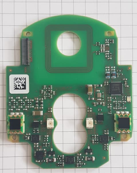
Click to zoom
Application Details
- Equipment Class
- DXX - Part 15 Low Power Communication Device Transmitter
- Date of Grant
- Sep 22, 2020
- Application Purpose
- Original Equipment
- Date of Application
- Sep 22, 2020
- Equipment Note
- NICCI NFC Unit
- Frequency Range
- 13.56000000 - 13.56000000
- Company
- PULSION Medical Systems SE
- Country
- Germany
Documents & Files
Document Text
Text extracted from the exhibit documents filed with the FCC. Open a document above to read the original.
Users Manual
O perator’s Manual Page 0 NICCI Technology PURPOSE This document is the master of instructions for use for NICCI technology. SCOPE n/a REFERENCES RefDoc ID Version Document Title [1] LAB-000194 04 NICCI System instructions for use set-up and design specification [2] SDS-000056 06* 2 CNAP - Alarms & Messages [3] REQ-000036 05 PR00678 Default Parameter [4] SDS-000062 01* 1 UI Integration Manual - User Interaction Specifications * 1 The IFU contents are according to Polarion baseline 23.07.2019. * 2 Every message is listed only once in the IFU (despite the different error codes). CHANGE HISTORY Version Edit Date Description Issuer Reference to the project (DCC, DCP) 01 28 May 2019 First release I. SichnaVIENNA 02 27 July 2019 1. Update of ‘Alarms and messages’ according to SDS-000056-05. 2. Changes in the SW description: •Explanation of grey bars in the pressure parameter field; •Addition of the term ‘CO calibration’ to the index; •Explanation of the curve icon in the NIBP history table. •Format improvements in chapter ‘D2 NICCI Sensor activation’. •Changes in the description of ‘NIBP only’ mode (chapter new ‘E2 NIBP only measurement’) 3. Minor wording/pictures improvements in the chapter ‘Setup&start’. 4. Updates according to LAB-000194-02: •chapter A1-3 (impact of RAC-000498- 06). •chapter B3 (impact of REQ-000065-08 and REQ-000036-05) •chapter A4-6: transfer of new/removing/update of warnings/cautions/notes •appendix O (addition of rated range of the sensor cuffs pressure 0-280 mmHg) I. SichnaVIENNA Operator’s Manual Page 0 NICCI Technology 03 13 Aug. 2019 1. Minor wording/pictures improvements in the chapter ‘Setup&start’. 2. Appendix O: addition of rated measurement range (20-250mmHg). 3. Update of ‘Alarms and messages’ according to SDS-000056-06. I. Sichna VIENNA 04 5 Sept. 2019 1. Chapter K: update according to LAB- 000194-03 (update of cleaning and disinfection agents, impact of REQ- 000065-09). I. Sichna VIENNA 05 18 Sept. 2019 1. Table 15 (electromagnetic immunity): update of ESD test level and ESD compliance level I. Sichna VIENNA 06 17 Dec. 2019 1. Addition of the placeholder for IFU unique identifier on the last page. I. Sichna VIENNA 07 27 Jan. 2020 1. Chapter P: update according to LAB- 000194-04 (ESD test level and ESD compliance level). 2. Chapter O: update of the weight of the NICCI Upper Arm Cuff. I. Sichna DCC-19-062 DCC-19-089 NICCI Technology Operator’s Manual MASTER Operator’s Manual Page III NICCI Technology NICCI components Table 1 – NICCI components NICCI components Component variants Article numbers NICCI Module Connected to the host monitor PulsioFlex PC4000 NICCI Module PC6500 NICCI Mouse* Connected to the NICCI Module NICCI Mouse PC6510 NICCI Upper Arm Cuff* Connected to the NICCI Module NICCI Upper Arm Cuff, S NICCI Upper Arm Cuff, M NICCI Upper Arm Cuff, L NICCI Upper Arm Cuff, XL PC6531 PC6532 PC6533 PC6534 NICCI Sensor* Connected to the NICCI Mouse NICCI Sensor S, single use NICCI Sensor M, single use NICCI Sensor L, single use PV6550 PV6551 PV6552 *Not made with Natural Rubber Latex NICCI compatibility: PulsioFlex PC4000 equipped with the software version 6.0 or higher. Page IV Operator’s Manual NICCI Technology About this manual This manual is an extension to the PulsioFlex operator’s manual (PC406*) that specifically describes the NICCI technology integrated into the PulsioFlex monitor PC4000. Both manuals need to be considered. * plus two digit language code according to ISO 639-1 This icon indicates a hazardous situation that, if not avoided, could result in death or serious injury. It may also describe potential serious adverse reactions and safety hazards. Additionaly, the WARNING is generally used as the signal word. This icon indicates a hazardous situation that, if not avoided, could result in minor or moderate injury. Additionaly, the CAUTION is generally used as the signal word. This icon indicates information considered important, but not hazard-related. The icon indicates items of information for which careful attention must be paid in order to avoid damage to the equipment or inaccurate data as well as operational errors. Additionaly, the NOTE is generally used as the signal word. This icon indicates helpful user information. All figures contained in this manual are examples and are subjects to change without further notice. Some localization rules in the figures may be omitted. Operator’s Manual Page V NICCI Technology Contents NICCI components ..................................................................................................................................................... III About this manual ...................................................................................................................................................... IV Contents ....................................................................................................................................................................... V List of figures ............................................................................................................................................................. VII List of tables ............................................................................................................................................................. VIII Frequently used functions ......................................................................................................................................... IX A General information .......................................................................................................................................... 10 1 Intended Use .................................................................................................................................................. 10 2 Indications for Use .......................................................................................................................................... 10 2.1 I…
Text truncated - open the document above for the full version.
External Photos
1/2 Internal Photos of NICCI NFC Unit PCBA http://www.getinge.com/ Pulsion Medical Systems SE Hans-Riedl-Str. 21 85622 Feldkirchen Germany Name of EUT: NICCI NFC Unit • Sensor Frontend PCBA (F000044) • NFC TAG Author: G. Grichtmaier Page: 1 of 2 Date: 22.09.2020 Advance information The NICCI NFC Unit consists of the Sensor Frontend PCBA (F000044) and a NFC Tag. Front view Sensor Frontend PCBA (F000044) Rear view Sensor Frontend PCBA (F000044) Figure 1: Sensor Frontend PCBA (F000044) 2/2 Front view of Sensor Frontend PCBA with integral antenna Rear view of Sensor Frontend PCBA with integral antenna Figure 2: Sensor Frontend PCBA (F000044) – Antenna Front view of tag (ICODE DNA) Rear view of tag (ICODE DNA) Figure 3: Front view of NFC Tag, used together with the NICCI NFC Unit (EUT)
ID Label/Location Info
31. AUG 2020 PULSION Medical Systems SE Company confidential 1 Typelabel of NICCI Mouse, holding Contains FCC ID 2AVPQGC269016 Typelabel if NICCI NFC Unit, holding FCC ID 2AVPQGC269016 31. AUG 2020 PULSION Medical Systems SE Company confidential 2 Example label showing the positon of the type label on top of NICCI Mouse.
Internal Photos
1/3 Internal Photos of NICCI NFC Unit PCBAs http://www.getinge.com/ Pulsion Medical Systems SE Hans-Riedl-Str. 21 85622 Feldkirchen Germany Name of EUT: NICCI NFC Unit • Sensor Frontend PCBA (F000044) • Controller PCBA (F000043) Here with NICCI Mouse Sensor, used for testing to bring EUT into operation. Author: G. Grichtmaier Page: 1 of 2 Version: V01_00 Date: 31.08.2020 Advance information The NICCI NFC Unit consists of the Sensor Frontend PCBA (F000044) and of the Controller PCBA (F000043). These parts are integrated in the NICCI Mouse Sensor. Front view Sensor Frontend PCBA (F000044) Rear view Sensor Frontend PCBA (F000044) Figure 1: Sensor Frontend PCBA (F000044) 2/3 Front view of Sensor Frontend PCBA with integral antenna Rear view of Sensor Frontend PCBA with integral antenna Figure 2: Sensor Frontend PCBA (F000044) – Antenna Front view of Controller PCBA (F000043) Rear view of Controller PCBA (F000043) Figure 3: Controller PCBA (F000043) 3/3 Front view of tag (ICODE DNA) Rear view of tag (ICODE DNA) Figure 4: Front view of NFC Tag, used together with the NICCI NFC Unit (EUT)
RF Exposure Info
31. AUG 2020 PULSION Medical Systems SE Company confidential 1 Table of contents 1 PURPOSE ............................................................................................................ 2 2 SCOPE ................................................................................................................. 2 3 REFERENCES ..................................................................................................... 2 4 DEFINITIONS ....................................................................................................... 2 5 DESCRIPTION OF DEVICE ................................................................................. 3 5.1 General product information ...............................................................................................3 5.2 Operational Description of RF components .........................................................................4 5.3 NFC Components ..............................................................................................................5 6 APPLICABLE STANDARDS ................................................................................. 5 7 EVALUATION METHODS .................................................................................... 5 8 CONSIDERATION ................................................................................................ 6 8.1 Introduction to standards ....................................................................................................6 8.1.1 Introduction to FCC 47 CFR § 2.1093 ....................................................................6 8.1.2 Introduction to FCC General RF Exposure Guidance .............................................6 8.2 Consideration of radiated power .........................................................................................7 8.2.1 NFC components ..................................................................................................7 8.2.2 Test report .............................................................................................................7 8.3 Additional research ............................................................................................................7 9 CONCLUSION ...................................................................................................... 8 31. AUG 2020 PULSION Medical Systems SE Company confidential 2 1 PURPOSE This document shows the evaluation of compliance with given limits for human exposure. 2 SCOPE In scope of the test is the NFC Unit on Sensor Frontend PCB (F00044). F00044 is part of e.g. the NICCI Hand Module (PC6510). 3 REFERENCES Ref Doc id Document name [1] N/A Website reference Legal Information Institute. (2020, August 24). 47 CFR § 2.1093 - Radiofrequency radiation exposure evaluation: portable devices. [ONLINE]. Available: https://www.law.cornell.edu/cfr/text/47/2.1093 [2] N/A Official document reference IEEE Std. C95.1, 1999 Edition EEE Standard for Safety Levels with Respect to Human Exposure to Electric, Magnetic, and Electromagnetic Fields, 0 Hz to 300 GHz [3] N/A Official document reference 447498 D01 General RF Exposure Guidance v06 October 23, 2015 [4] REP-000782 - 01 N4420013 - NFC Module - Report [5] N/A Official document reference Numerical Assessment of Specific Absorption Rate in the Human Body Caused by NFC Devices 03 June 2010 4 DEFINITIONS Definition Explanation NFC Near Field Communication PCB Princted Circuit Board NICCI Name of Pulsion’s Medical Device RF Radio Frequency SAR Specific Absorption Rate 31. AUG 2020 PULSION Medical Systems SE Company confidential 3 5 DESCRIPTION OF DEVICE 5.1 General product information Figure 1: General product information of NICCI The NICCI Module (2) is an accessory of PulsioFlex (1) monitor. To the NICCI Module, the NICCI Mouse (3) is connected. Depending on the size of the patient, a specific NICCI sensor ((4), size S, M, or L) is clipped on the NICCI Mouse. The NICCI Upper Arm Cuff (5) serves as reference measuring tool for the system. A patient applies its finger to the NICCI Sensor. In this way, its blood pressure can be measured. The NFC module, which is item of interest for this document, is integrated into NICCI Mouse for bringing it into operation. 31. AUG 2020 PULSION Medical Systems SE Company confidential 4 5.2 Operational Description of RF components The NICCI NFC Unit is used to detect the NFC Tag in NICCI Sensor, when attached to NICCI Mouse. When attached, it exchanges data via wireless connection. The microcontroller receives the information from NFC reader chip if the NFC tag is present or not and forwards this information to a host module (e.g. NICCI Module) via serial interface. The NFC reader chip is situated on the Sensor Fronted PCBA F000044, together with the integral antenna and its crystal oscillator with 27.12 MHz. The NFC reader chip works with an operating frequency of 13.56 MHz to communicate with the NFC tag. When the sensor is clipped on the mouse, there is a distance of 8.6 mm between the antenna and the NFC Tag. The communication between NFC reader chip and microcontroller 2nd μC is through I2C serial interface using a frequency of 400 kHz. For communication the protocol according to ISO 15693 is used. The microcontroller 2 nd μC is responsible for the communication with the NFC reader chip and uses a clock frequency of 12 MHz. The microcontroller 2nd μC is situated on the Controller PCBA F000043, together with another microcontroller DSP, which uses a clock frequency of 20 MHz. The microcontroller DSP is responsible for the communication with the host module. Figure 2: Block diagram of NICCI NFC Unit with NFC Tag 31. AUG 2020 PULSION Medical Systems SE Company confidential 5 5.3 NFC Components Table 1 shows the exact NFC components: Table 1: Key components of RF module Test item component Type NFC reader chip NXP CLRC663 NFC reader antenna Integrated antenna design, quadratic with 2.5cm side length and four turns …
Text truncated - open the document above for the full version.
Test Report
This document was signed electronically. SGS Germany GmbH, Hofmannstr. 50, D-81379 Munich, and Traunreuter Str. 3, D-82538 Geretsried-Gelting are testing facilities for ELECTRO-MECH. COMPONENTS TESTING ENVIRONMENTAL SIMULATION ELECTROMAGNETIC COMPATIBILITY MEDICAL DEVICE TESTING BATTERY TESTING PRODUCT SAFETY TELECOM CONFORMANCE TESTS Phone +49 89-787475-100, Fax +49 89-787475-114, Internet www.sgs-cqe.de The test report shall not be r eproduced except in full without the written approval of the testing laboratory SGS Germany GmbH Test Report No.: N4420010 FCC ID: 2AVPQGC269016 Order No.: N442 Pages: 57 Client: PULSION Medical Systems SE Equipment Under Test: NICCI NFC Unit Manufactu rer / Importer: PULSION Medical Systems SE Task: Compliance with the requirements mentioned below: Test Specification(s): [covered by accreditation] • FCC 47 CFR Part 15 Test Specification(s): [not covered by accreditation] • RSS Gen Issue 5 • RSS-210 Issue 10 Result: The EUT complies with the requirements of the test specifica- tions. The results relate only to the items tested as described in this test report. approved by: Date Signature Bauer Lab Manager EMC Sep 08, 2020 Test Report No.: N4420010 NICCI NFC Unit Page 2 / 57 The test report shall not be r eproduced except in full without the written approval of the testing laboratory CONTENTS 1 Result Summary ...................................................................................................................... 5 2 References ............................................................................................................................... 6 2.1 Specification(s) .................................................................................................................... 6 2.2 Glossary .............................................................................................................................. 6 3 General Information ................................................................................................................ 7 3.1 Identification of Client .......................................................................................................... 7 3.2 Test Laboratory ................................................................................................................... 7 3.3 Time Schedule .................................................................................................................... 7 3.4 Participants ......................................................................................................................... 7 3.5 Environmental conditions .................................................................................................... 7 4 Equipment Under Test ............................................................................................................ 8 4.1 Operational conditions ...................................................................................................... 10 4.1.1 Software ..................................................................................................................... 10 4.1.2 Radio parameters ....................................................................................................... 10 4.1.3 Operation modes ........................................................................................................ 11 4.1.4 Test configurations ..................................................................................................... 11 4.2 Hardware Configuration .................................................................................................... 12 4.2.1 Components of the EUT ............................................................................................. 12 4.2.2 Interface description ................................................................................................... 12 4.2.2.1 Power supply port ................................................................................................ 12 4.2.2.2 Earthing and Grounding connections ................................................................. 12 4.2.2.3 Communication and signal ports ....................................................................... 13 4.2.3 Cabling ....................................................................................................................... 13 4.2.4 Clock frequencies of the EUT resulting in determination of frequency range ............. 13 4.2.5 External protection devices or measures.................................................................... 14 4.2.6 Modifications during the test ....................................................................................... 14 4.2.7 Operation and monitoring equipment ......................................................................... 14 4.3 Deviations from Standard .................................................................................................. 14 5 Test Equipment ...................................................................................................................... 15 5.1 Test Facility ....................................................................................................................... 15 5.2 Calibration of the Test Equipment ..................................................................................... 15 5.3 Measurement Uncertainty ................................................................................................. 16 6 Test Conditions and Results ................................................................................................ 17 6.1 Test No. 1: Conducted Emissions (§ 15.207) ................................................................... 17 6.1.1 Purpose ...................................................................................................................... 17 Test Report No.: N4420010 NICCI NFC Unit Page 3 / 57 The test report shall not be r epro…
Text truncated - open the document above for the full version.
Test Setup Photos
1/5 Test Setup Photos for NICCI NFC Unit with Sensor Frontend PCBA (F000044) and Controller PCBA (F000043) Test Report: N4420010 1.1.1 Test No. 1: Conducted Emissions (§ 15.207) Figure 1: Test Setup Conducted Emissions (150 kHz – 30 MHz) – Configurations 3, 4, 5 2/5 1.1.2 Test No. 2: Occupied Bandwidth (§ 15.215c) Figure 2: Test Setup Occupied Bandwidth – Configuration 2 3/5 1.1.3 Test No. 3: Radiated Emissions (§ 15.205, § 15.209, § 15.225a-d) Figure 3: Test Setup Radiated Emission 30 MHz – 1 GHz – Configurations 1, 2 4/5 Figure 4: Test Setup Radiated Emission 9 kHz – 30 MHz – Configuration 1, 2, 3, 4 5/5 1.1.4 Test No. 4: Frequency Stability (§ 15.225e) Figure 5: Test Setup – Frequency Stability with voltage or/and Temperature variation – Configuration 2
Contact Information
Applicant
Thomas Leitner
Technical Contact
PULSION Medical Systems SEThomas Leitner
[email protected]49 89 459914
PULSION Medical Systems SE · Feldkirchen · Germany
Non-Technical Contact
PULSION Medical Systems SEJenniu Ritter
[email protected]49 89 459914
Test Firm
SGS Germany GmbHJosef Bauer
Technical Specifications
| # | Rule Parts | Frequency Range | Power Output |
|---|---|---|---|
| 1 | 15C | 13.56 MHz - 13.56 MHz | - |