2AVQ70109-UPPUUniversal Passive Provisioning Unit
Tappy Technologies Limited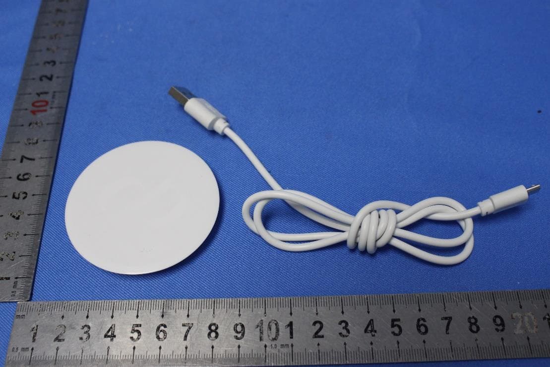
Click to zoom
Application Details
- Equipment Class
- DTS - Digital Transmission System
- Date of Grant
- Jan 18, 2021
- Application Purpose
- Original Equipment
- Date of Application
- Jan 18, 2021
- Equipment Note
- Universal Passive Provisioning Unit
- Frequency Range
- 2402.00000000 - 2480.00000000
- Company
- Tappy Technologies Limited
- Country
- Hong Kong
Documents & Files
Document Text
Text extracted from the exhibit documents filed with the FCC. Open a document above to read the original.
Users Manual
‘UPPU CIRCLE’ Set-up Guide –Add a Wearable TappyWearable Token Service Provider 1. Download the “Tappy“ mobile application from Google Play / Apple Store and follow the on-screen instructions 2. Register a new account or login to your existing account using the registration/login screen on the mobile application 3. Connect Wearable a. Placing the wearable on the top of UPPU CIRCLE carefully b. Connect the UPPU CIRCLE to a USB power source with the cable included, ensure the light indicator is turned on c. Add your wearable to your account by tapping (+) button on the home screen and press “Next” to proceed. The pairing will happen automatically if only one UPPU CIRCLE is visible within range. d. You may be presented with a list of UPPU CIRCLE to select, if there are multiple CIRCLE visible within range. Match the Bluetooth name with the name on the sticker on the back of the UPPU CIRCLE. If there is only one UPPU in the vicinity, the app will automatically pair with it e. Once successful, you should see “Wearable Connected” with the picture of the wearable. f. Please refer to FAQ for troubleshooting any issues. ‘UPPU CIRCLE’ Set-up Guide –Add card / delete card / remove wearable TappyWearable Token Service Provider 4. Add card a. Please ensure you have the wearable connected (Refer to section 3) before proceeding to add a card b. Tap on “Add a Card” on the bottom of the last screen c. Follow the instructions on the mobile application d. Once the card is added, you may be required to authenticate with your bank for security reasons to activate and use the wearable for contactless payments e. Please refer to FAQ for troubleshooting any issues. 5. Delete card from wearable a. Please ensure you have the wearable connected (Refer to section 3) b. Navigate to: Settings -> Linked Credit Cards -> Select the card to delete by swiping through the carousel c. Tap on the 3-dot’s in the top-right and choose the “Delete Card” option. d. Please refer to FAQ for troubleshooting any issues. 6. Remove Wearable a. A wearable can be removed (Unpair) by navigating to home screen and tapping on the 3-dot’s in the top-right. Then choose "Remove Wearable” option. b. A confirmation dialog will be displayed, and the user must select YES for the wearable to be removed. c. Please refer to FAQ for troubleshooting any issues. 7. Pay with Wearable a. Please ensure you have added a card (Refer to section 4) to the wearable before proceeding to pay with your wearable b. It is as simple as bringing your wearable closer to, or tap on the POS terminal c. Please refer to FAQ for troubleshooting any issues. ‘UPPU CIRCLE’ Product Specification TappyWearable Token Service Provider Item DescriptionRemark LEDindicatorBluetoothconnectionindicator 1PCS,Green Flashing when not connected, and always on after connection Wirelesscommunication Bluetooth 2.4G RFID 13.56Mhz Powerconsumption Workingcurrent MAX.:180mA Stand-bycurrent MAX.:50mA DCinput MICROUSB-5V Workingenvironment Operatingtemperature 10°C--50°C Storagetemperature 10°C--50°C Relativehumidity 5% ~ 95%, no freezing SwitchmachineSystembootmethod Power-onbydefault Size(LxWxH) 65.84*65.84mm*8mm Weight 16g FCC compliance statement This device complies with Part 15 of the FCC Rules. Operation is subject to the following two conditions: (1) this device maynot cause harmful interference, and (2) this device must accept any interference received, including interference that may cause undesired operation. changes or modifications not expressly approved by the party responsible for compliance could void the user’s authority to operate the equipment. This equipment has been tested and found to comply with the limits for a Class B digital device, pursuant to Part 15 of the FCC Rules. These limits are designed to provide reasonable protection against harmful interference in a residential installation. This equipment generates, uses and can radiateradio frequency energy and, if not installed and used in accordance with the instructions, may cause harmful interference to radio communications. However, there is no guarantee that interference will not occur in a particular installation. If this equipment does cause harmful interference to radio or television reception, which can be determined by turning the equipment off and on, the user is encouraged to try to correct the interference by one or more of the following measures: --Reorient or relocate the receiving antenna. --Increase the separation between the equipment and receiver. --Connect the equipment into an outlet on a circuit different from that to which the receiver is connected. --Consult the dealer or an experienced radio/TV technician for help. Trade Name: UPPU Model No.: UPPU CIRCLE Responsible Party –U.S. Contact Information US Company Name Address Telephone number or internet contact information ISED compliance statement This device contains licence-exempt transmitter(s)/receiver(s) that comply with Innovation, Science and Economic Development Canada’s licence-exempt RSS(s). Operation is subject to the following two conditions: (1) This device may not cause interference. (2) This device must accept any interference, including interference that may cause undesired operation of the device. L’émetteur/récepteurexempt de licencecontenudansle présentappareilestconformeaux CNR d’Innovation, Sciences et DéveloppementéconomiqueCanada applicables aux appareilsradio exempts de licence. L’exploitationestautoriséeaux deuxconditions suivantes: (1) L’appareilne doitpas produirede brouillage; (2) L’appareildoitaccepter tout brouillageradioélectriquesubi, mêmesile brouillageestsusceptible d’encompromettrele fonctionnement. ISED Radiation Exposure statement This equipment complies with IC RSS-102 radiation exposure limits set forth for an uncontrolled environment. Cetéquipementestconformeaux limitesd'expositionaux radiations IC CNR-102 établiespour un environnementnon contrôlé. Complies with IMDA Standards DA107248 Singapore TRA Registered No…
Text truncated - open the document above for the full version.
External Photos
SGS-CSTC Standards Technical Services Co., Ltd. Shenzhen Branch Page: 1 of 5 External Photos for SZEM2012012647CR FCC ID: 2AVQ70109-UPPU SGS-CSTC Standards Technical Services Co., Ltd. Shenzhen Branch Page: 2 of 5 1 EUT Constructional Details SGS-CSTC Standards Technical Services Co., Ltd. Shenzhen Branch Page: 3 of 5 SGS-CSTC Standards Technical Services Co., Ltd. Shenzhen Branch Page: 4 of 5 SGS-CSTC Standards Technical Services Co., Ltd. Shenzhen Branch Page: 5 of 5
Internal Photos
SGS-CSTC Standards Technical Services Co., Ltd. Shenzhen Branch Page: 1 of 3 Internal Photos for SZEM2012012647CR FCC ID: 2AVQ70109-UPPU SGS-CSTC Standards Technical Services Co., Ltd. Shenzhen Branch Page: 2 of 3 1 EUT Constructional Details SGS-CSTC Standards Technical Services Co., Ltd. Shenzhen Branch Page: 3 of 3
RF Exposure Info
SGS-CSTC Standards Technical Services Co., Ltd. Shenzhen Branch Report No.: SZEM201201264704 Page: 1 of 7 Keny Xu EMC Laboratory Manager 1 Cover page SAR Evaluation Report Application No.: SZEM2012012647CR Applicant: Tappy Technologies Limited Address of Applicant: Unit A 3/F Yee Lim Ind Bldg Stage 2, 8 Ka Ting Rd Kwai Chung NT Hong Kong Manufacturer: Tappy Technologies Limited Address of Manufacturer: Unit A 3/F Yee Lim Ind Bldg Stage 2, 8 Ka Ting Rd Kwai Chung NT Hong Kong Equipment Under Test (EUT): Product Name: Universal Passive Provisioning Unit Model No.: UPPU CIRCLE Trade mark: UPPU FCC ID: 2AVQ70109-UPPU Standards: 47 CFR Part 1.1307 47 CFR PART 2, Subpart J, Section 2.1093 KDB447498D01 General RF Exposure Guidance v06 Date of Receipt: 2020-12-09 Date of Test: 2020-12-10 to 2021-01-04 Date of Issue: 2021-01-04 Test Result : PASS* * In the configuration tested, the EUT complied with the standards specified above. SGS-CSTC Standards Technical Services Co., Ltd. Shenzhen Branch Report No.: SZEM201201264704 Page: 2 of 7 2 Version Revision Record Version Chapter Date Modifier Remark 01 2021-01-04 Original Authorized for issue by: Leo Li /Project Engineer Eric Fu /Reviewer SGS-CSTC Standards Technical Services Co., Ltd. Shenzhen Branch Report No.: SZEM201201264704 Page: 3 of 7 3 Contents Page 1 COVER PAGE .............................................................................................................................................. 1 2 VERSION ...................................................................................................................................................... 2 3 CONTENTS .................................................................................................................................................. 3 4 GENERAL INFORMATION .......................................................................................................................... 4 4.1 GENERAL DESCRIPTION OF EUT ............................................................................................................. 4 4.2 TEST LOCATION ...................................................................................................................................... 5 4.3 TEST FACILITY ........................................................................................................................................ 5 4.4 DEVIATION FROM STANDARDS ................................................................................................................. 5 4.5 ABNORMALITIES FROM STANDARD CONDITIONS ....................................................................................... 5 4.6 OTHER INFORMATION REQUESTED BY THE CUSTOMER ............................................................................. 5 5 SAR EVALUATION ...................................................................................................................................... 6 5.1 RF EXPOSURE COMPLIANCE REQUIREMENT ............................................................................................ 6 5.1.1 Standard Requirement ..................................................................................................................... 6 5.1.2 Limits ................................................................................................................................................ 6 5.1.3 EUT RF Exposure ............................................................................................................................ 7 SGS-CSTC Standards Technical Services Co., Ltd. Shenzhen Branch Report No.: SZEM201201264704 Page: 4 of 7 4 General Information 4.1 General Description of EUT Power Supply: DC 5V from USB port Cable: USB cable: 80cm unshielded For NFC: Operation Frequency: 13.56MHz Modulation Type: ASK Antenna Type: Loop Antenna Antenna Gain: 0dBi Max. power (including tune-up tolerance) -35.26dBm* For BT: Operation Frequency: 2402MHz to 2480MHz Bluetooth Version: V4.2 LE Modulation Type: GFSK Number of Channels: 40 Channel Spacing: 2MHz Antenna Type: Monopole Antenna Antenna Gain: 0.55dBi Max. power (including tune-up tolerance) -5.8dBm (*) Refer to test report SZEM201201264703 for EUT test Max Conducted Peak Output Power(including tune- up tolerance) value. E=EIRP-20logD+104.7 E=59.90dBuv/m(Refer to test report SZEM200700682503) D=3m EIRP=59.90-(-20log(3)+104.7) EIRP=-35.26dBm(0.00030mW) SGS-CSTC Standards Technical Services Co., Ltd. Shenzhen Branch Report No.: SZEM201201264704 Page: 5 of 7 4.2 Test Location All tests were performed at: SGS-CSTC Standards Technical Services Co., Ltd. Shenzhen Branch No. 1 Workshop, M-10, Middle section, Science & Technology Park, Shenzhen, Guangdong, China 518057 Telephone: +86 (0) 755 2601 2053 Fax: +86 (0) 755 2671 0594 No tests were sub-contracted. 4.3 Test Facility The test facility is recognized, certified, or accredited by the following organizations: • A2LA (Certificate No. 3816.01) SGS-CSTC Standards Technical Services Co., Ltd., Shenzhen EMC Laboratory is accredited by the American Association for Laboratory Accreditation(A2LA). Certificate No. 3816.01. • VCCI The 3m Fully-anechoic chamber for above 1GHz, 10m Semi-anechoic chamber for below 1GHz, Shielded Room for Mains Port Conducted Interference Measurement and Telecommunication Port Conducted Interference Measurement of SGS-CSTC Standards Technical Services Co., Ltd. have been registered in accordance with the Regulations for Voluntary Control Measures with Registration No.: G-20026, R-14188, C-12383 and T-11153 respectively. • FCC –Designation Number: CN1178 SGS-CSTC Standards Technical Services Co., Ltd., Shenzhen EMC Laboratory has been recognized as an accredited testing laboratory. Designation Number: CN1178. Test Firm Registration Number: 406779. • Innovation, Science and Economic Development Canada SGS-CSTC Standards Technical Services Co., Ltd., Shenzhen EMC Laboratory has been recognized by ISED as an accredited test…
Text truncated - open the document above for the full version.
Test Report
SGS-CSTC Standards Technical Services Co., Ltd. Shenzhen Branch Report No.: SZEM201201264702 Page: 1 of 54 Keny Xu EMC Laboratory Manager TEST REPORT Application No.: SZEM2012012647CR Applicant: Tappy Technologies Limited Address of Applicant: Unit A 3/F Yee Lim Ind Bldg Stage 2, 8 Ka Ting Rd Kwai Chung NT Hong Kong Manufacturer: Tappy Technologies Limited Address of Manufacturer: Unit A 3/F Yee Lim Ind Bldg Stage 2, 8 Ka Ting Rd Kwai Chung NT Hong Kong Equipment Under Test (EUT): EUT Name: Universal Passive Provisioning Unit Model No.: UPPU CIRCLE Trade Mark: UPPU FCC ID: 2AVQ70109-UPPU Standard(s) : 47 CFR Part 15, Subpart C 15.247 Date of Receipt: 2020-12-09 Date of Test: 2020-12-10 to 2021-01-04 Date of Issue: 2021-01-04 Test Result: Pass* * In the configuration tested, the EUT complied with the standards specified above. SGS-CSTC Standards Technical Services Co., Ltd. Shenzhen Branch Report No.: SZEM201201264702 Page: 2 of 54 Revision Record Version Chapter Date Modifier Remark 01 2021-01-04 Original Authorized for issue by: Leo Li /Project Engineer Eric Fu /Reviewer SGS-CSTC Standards Technical Services Co., Ltd. Shenzhen Branch Report No.: SZEM201201264702 Page: 3 of 54 2 Test Summary Radio Spectrum Technical Requirement Item Standard Method Requirement Result Antenna Requirement 47 CFR Part 15, Subpart C 15.247 N/A 47 CFR Part 15, Subpart C 15.203 & 15.247(b)(4) Pass Radio Spectrum Matter Part Item Standard Method Requirement Result Conducted Emissions at AC Power Line (150kHz-30MHz) 47 CFR Part 15, Subpart C 15.247 ANSI C63.10 (2013) Section 6.2 47 CFR Part 15, Subpart C 15.207 Pass Minimum 6dB Bandwidth 47 CFR Part 15, Subpart C 15.247 ANSI C63.10 (2013) Section 11.8.1 47 CFR Part 15, Subpart C 15.247a(2) Pass Conducted Peak Output Power 47 CFR Part 15, Subpart C 15.247 ANSI C63.10 (2013) Section 11.9.1 47 CFR Part 15, Subpart C 15.247(b)(3) Pass Power Spectrum Density 47 CFR Part 15, Subpart C 15.247 ANSI C63.10 (2013) Section 11.10.2 47 CFR Part 15, Subpart C 15.247(e) Pass Conducted Band Edges Measurement 47 CFR Part 15, Subpart C 15.247 ANSI C63.10 (2013) Section 11.13.3.2 47 CFR Part 15, Subpart C 15.247(d) Pass Conducted Spurious Emissions 47 CFR Part 15, Subpart C 15.247 ANSI C63.10 (2013) Section 11.11 47 CFR Part 15, Subpart C 15.247(d) Pass Radiated Emissions which fall in the restricted bands 47 CFR Part 15, Subpart C 15.247 ANSI C63.10 (2013) Section 6.10.5 47 CFR Part 15, Subpart C 15.205 & 15.209 Pass Radiated Spurious Emissions 47 CFR Part 15, Subpart C 15.247 ANSI C63.10 (2013) Section 6.4,6.5,6.6 47 CFR Part 15, Subpart C 15.205 & 15.209 Pass SGS-CSTC Standards Technical Services Co., Ltd. Shenzhen Branch Report No.: SZEM201201264702 Page: 4 of 54 3 Contents Page 1 COVER PAGE ..................................................................................................................................... 1 2 TEST SUMMARY ................................................................................................................................. 3 3 CONTENTS ......................................................................................................................................... 4 4 GENERAL INFORMATION .................................................................................................................. 6 4.1 DETAILS OF E.U.T. ......................................................................................................................... 6 4.2 DESCRIPTION OF SUPPORT UNITS .................................................................................................... 6 4.3 MEASUREMENT UNCERTAINTY ......................................................................................................... 6 4.4 TEST LOCATION ............................................................................................................................. 7 4.5 TEST FACILITY ............................................................................................................................... 7 4.6 DEVIATION FROM STANDARDS ......................................................................................................... 7 4.7 ABNORMALITIES FROM STANDARD CONDITIONS ................................................................................. 7 5 EQUIPMENT LIST ............................................................................................................................... 8 6 RADIO SPECTRUM TECHNICAL REQUIREMENT ............................................................................12 6.1 ANTENNA REQUIREMENT ................................................................................................................12 6.1.1 Test Requirement: ..................................................................................................................12 6.1.2 Conclusion ..............................................................................................................................12 7 RADIO SPECTRUM MATTER TEST RESULTS .................................................................................13 7.1 CONDUCTED EMISSIONS AT AC POWER LINE (150KHZ-30MHZ) ........................................................13 7.1.1 E.U.T. Operation .....................................................................................................................13 7.1.2 Test Setup Diagram ................................................................................................................13 7.1.3 Measurement Procedure and Data .........................................................................................14 7.2 MINIMUM 6DB BANDWIDTH .............................................................................................................17 7.2.1 E.U.T. Operation .....................................................................................................................17 7.2.2 Test Setup Diagram ......................................................…
Text truncated - open the document above for the full version.
Test Setup Photos
SGS-CSTC Standards Technical Services Co., Ltd. Shenzhen Branch Page: 1 of 3 Setup Photos for SZEM2012012647CR FCC ID: 2AVQ70109-UPPU SGS-CSTC Standards Technical Services Co., Ltd. Shenzhen Branch Page: 2 of 3 1 Photographs 1.1 Conducted Emissions at AC Power Line (150kHz-30MHz) Test Setup 1.2 Radiated Spurious Emissions Test Setup SGS-CSTC Standards Technical Services Co., Ltd. Shenzhen Branch Page: 3 of 3 1.3 Radiated Emissions Which Fall in The Restricted Bands Test Setup
Contact Information
Applicant
SW Kwok(Operations Manager)
Technical Contact
SGS-CSTC Standards Technical Services Co., Ltd.Keny Xu
[email protected]86-755-25328629
No.1 Workshop, M-10, Middle Section, · Shenzhen · China
Test Firm
SGS-CSTC Standards Technical Services Co., LtdDerek Yang
[email protected]+86 0135 6484 8721
Technical Specifications
| # | Rule Parts | Frequency Range | Power Output |
|---|---|---|---|
| 1 | 15C | 2.40 GHz - 2.48 GHz | 300.00 µW |
Other Applications from Tappy Technologies Limited
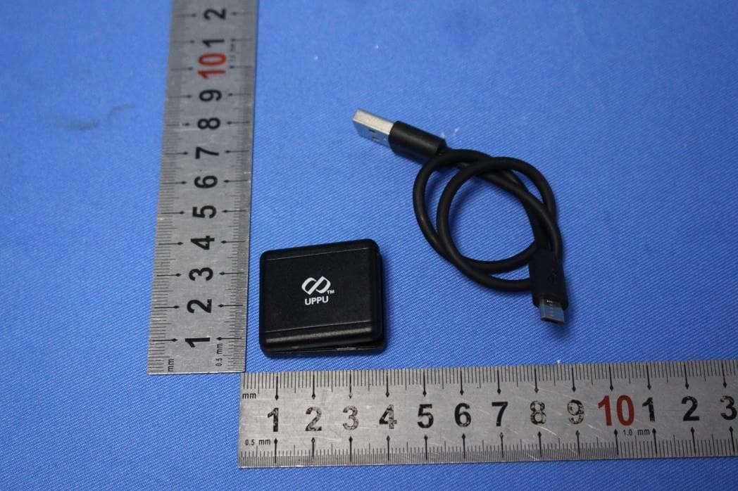
2AVQ70072-UPPU
Nov 18, 2020Universal Passive Provisioning Unit
Equipment Class
DXX - Part 15 Low Power Communication Device Transmitter