2AVQC-NOMADPortable Personal Lighting Device
Lucere Inc.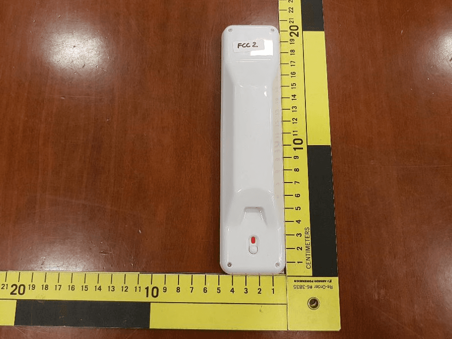
Click to zoom
Application Details
- Equipment Class
- DXX - Part 15 Low Power Communication Device Transmitter
- Date of Grant
- Mar 16, 2020
- Application Purpose
- Original Equipment
- Date of Application
- Mar 15, 2020
- Equipment Note
- Portable Personal Lighting Device
- Frequency Range
- 903.00000000 - 927.00000000
- Company
- Lucere Inc.
- Country
- Canada
Documents & Files
Document Text
Text extracted from the exhibit documents filed with the FCC. Open a document above to read the original.
Users Manual
Welcome to LucereLight ™ 23 BRIGHTNESS CONTROL Adjust brightness by gently tapping the + or – brightness control icons on the bottom of the light. You can also press and hold, and the brightness will ramp in the direction associated with the icon. NOTE: FOR BEST RESULTS, LEAVE ALL LIGHTS ON IN THE BATHROOM WHEN USING THE LUCERELIGHT. INDICATOR LIGHTS The two LucereLights have built-in radio communications, so that when you press the icons on one light to change illumination, the other light will automatically correspond. An indicator at the top of the light informs you of battery status: Red (Blink) – battery low, charging required Yellow – charging Green – charging complete POWER SAVER SWITCH The power-saving ON/OFF slide switch is located on the back of the light. Fully charged, LucereLight has power for continuous operation for one hour at maximum brightness. In power-save mode the switch disables power consumption and all functions (except charging) so that the unit can be stored or left unattended for a long period and cannot turn on accidentally when packed in luggage or carried in a purse. This ensures the light is ready with a full battery when you need it. This switch also disables the internal radio transmitter so that it does not cause interference to aircraft systems and meets all Federal Aviation rules. NOTE: The light constantly uses a small amount of electricity to power the icon sensors and radio receiver. BEFORE ATTACHING To ensure correct adhesion, make sure the mirror or glass is totally clean before attaching the silicone base or permanent mount. Also, ensure the back surface of the silicone base is clean. If any dust or lint is on it, rinse under warm water and shake dry or use a lint free microfiber cloth. WHAT’S IN THE BOX LUCERE LIGHTS (2) SILICONE BASES (2) PLASTIC PLATES (2) USB CHARGER USB CHARGING CABLES (2) DOUBLE-SIDED TAPE (4) USER MANUAL ONE-YEAR WARRANTY OVERVIEW Most mirrors do not have adequate lighting. By attaching LucereLight ™ to your mirror you will have the best natural lighting when you need it, wherever you need it. Lighting engineers and optical experts have designed LucereLight to illuminate your face perfectly,. LucereLight can be placed at the height of your choosing and can be moved easily for recharging and/or traveling. The light can be dimmed to find the lighting level best suited for you. LucereLight is available in Icy Blue, Dusty Rose and Metallic Silver. FEATU RES Note: The power-saving ON/OFF switch located at the back of the light should be turned to the ON/GREEN position for the operation of LucereLight. ON-OFF BUTTON To turn the lights on or off press the LucereLight logo light icon on the bottom of the light between the + and – icons. Pressing the + or – icons will also turn on the light. plastic plateUSB cable & chargersilicone basedouble-sided tape LucereLight ™ 45 ATTACHING These are the simple steps to attaching LucereLight to your bathroom mirror. (Click on link xxxx to see instructional on youtube.com) 1. ATTACHING TWO LIGHTS (see illustration) For optimum effective lighting, LucereLight has been designed for use in pairs. Choose placement of the silicone bases and the lights vertically on the mirror on either side of your face to give maximum illumination. First, mount the lights by firmly pressing the silicone bases on to the mirror. Then, simply take the lights and place them on to the silicone bases. The LucereLight has a built-in magnet that attracts to a piece of steel inside the silicone base. The curved shape of the mount allows you to easily adjust the angle of the light for optimum illumination. NOTE: After each use it is recommended to remove LucereLights from the silicone bases in order to protect them. If you are traveling or want the lights in a different location, you simply peel off the silicone bases from the mirror and re-attach the silicone bases to any clean glass surface as described above. 2. ATTACHING ONE LIGHT (see illustration) If you choose to use only one LucereLight, you may want to place it horizontally on the mirror above your face, or vertically opposite your face and move from side to side to get maximum illumination on both sides of your face. (Follow mounting instructions above) 3. FOR LONG TERM ATTACHMENT (see illustration) For long term attachment use the enclosed removable two-sided tape and attach the plastic plate(s) directly to your mirror where you desire to have the light(s) on a long-term basis. Press the silicone base(s) firmly on to the plastic plate(s). Press all around the periphery. The two holes on the silicone base fit on to the two prongs on the plastic plate. The silicone base is designed to cling to the plastic plate and will stay there permanently until peeled off. (See above instructions for placement of LucereLights for maximum illumination) PAIRING SINGLE LIGHTS If you already own a set of LucereLights, or a single light, and want to add lights to your collection, then you can purchase as many lights as you want. Each LucereLight has the ability to pair radio communication with each other. Follow these simple steps. 1. Ensure both units are NOT in airplane mode (check that the switch on the back indicates green, not red) 2. On one of the units, simultaneously press and hold the power button and then, increase brightness icon. 3. After about 5 seconds the indicator LED will start to blink green. 4. On the other unit, press and hold the power button and then decrease brightness icon. 5. After about 5 seconds the indicator LED will start to blink red. 6. After a few red blinks it should flash green once and stop. The first blinking green unit will continue to blink. 7. Press any button on the unit with the blinking green LED to make it stop. 8. The units should now be paired. Any input on one unit should also affect the other one. It’s now ready for use. TAKING CARE OF LUCERELIGHT MAINTENANCE To ensure maximum adhesion, make sure the mirror or glass is totally clean bef…
Text truncated - open the document above for the full version.
External Photos
Report File #: 7169007240R-000 © TÜV SÜD Canada Inc. This test report shall not be reproduced except in full, without written approval of TÜV SÜD Canada Inc. Exhibit: External Photos FCC ID: 2AVQC-NOMAD IC: 25878-NOMAD Client Lucere Inc. Product Lucere Nomad Standard(s) RSS 210 Issue 10:2019 FCC Part 15 Subpart 15.249 Page 2 of 5 Report Issued: 2/25/2020 Report File #: 7169007240R-000 © TÜV SÜD Canada Inc. This test report shall not be reproduced except in full, without written approval of TÜV SÜD Canada Inc. Figure 1 ‒ EUT Close Up - Front Client Lucere Inc. Product Lucere Nomad Standard(s) RSS 210 Issue 10:2019 FCC Part 15 Subpart 15.249 Page 3 of 5 Report Issued: 2/25/2020 Report File #: 7169007240R-000 © TÜV SÜD Canada Inc. This test report shall not be reproduced except in full, without written approval of TÜV SÜD Canada Inc. Figure 2 ‒ EUT Close Up - Back Client Lucere Inc. Product Lucere Nomad Standard(s) RSS 210 Issue 10:2019 FCC Part 15 Subpart 15.249 Page 4 of 5 Report Issued: 2/25/2020 Report File #: 7169007240R-000 © TÜV SÜD Canada Inc. This test report shall not be reproduced except in full, without written approval of TÜV SÜD Canada Inc. Figure 3 ‒ EUT Close Up - Sides Client Lucere Inc. Product Lucere Nomad Standard(s) RSS 210 Issue 10:2019 FCC Part 15 Subpart 15.249 Page 5 of 5 Report Issued: 2/25/2020 Report File #: 7169007240R-000 © TÜV SÜD Canada Inc. This test report shall not be reproduced except in full, without written approval of TÜV SÜD Canada Inc. Figure 4 ‒ EUT Close Up - Charger
ID Label/Location Info
Report File #: 7169007240R-000 © TÜV SÜD Canada Inc. This test report shall not be reproduced except in full, without written approval of TÜV SÜD Canada Inc. Exhibit: Sample Label and Location FCC ID: 2AVQC-NOMAD IC: 25878-NOMAD Client Lucere Inc. Product Lucere Nomad Standard(s) RSS 210 Issue 10:2019 FCC Part 15 Subpart 15.249 Page 2 of 2 Report Issued: 2/26/2020 Report File #: 7169007240R-000 © TÜV SÜD Canada Inc. This test report shall not be reproduced except in full, without written approval of TÜV SÜD Canada Inc. Label Location on Device Sample Label 1in x 1in
Internal Photos
Report File #: 7169007240R-000 © TÜV SÜD Canada Inc. This test report shall not be reproduced except in full, without written approval of TÜV SÜD Canada Inc. Exhibit: Internal Photos FCC ID: 2AVQC-NOMAD IC: 25878-NOMAD Client Lucere Inc. Product Lucere Nomad Standard(s) RSS 210 Issue 10:2019 FCC Part 15 Subpart 15.249 Page 2 of 6 Report Issued: 2/25/2020 Report File #: 7169007240R-000 © TÜV SÜD Canada Inc. This test report shall not be reproduced except in full, without written approval of TÜV SÜD Canada Inc. Figure 1 – EUT Internal Photo Main Board - Front Client Lucere Inc. Product Lucere Nomad Standard(s) RSS 210 Issue 10:2019 FCC Part 15 Subpart 15.249 Page 3 of 6 Report Issued: 2/25/2020 Report File #: 7169007240R-000 © TÜV SÜD Canada Inc. This test report shall not be reproduced except in full, without written approval of TÜV SÜD Canada Inc. Figure 2 – EUT Internal Photo Front Client Lucere Inc. Product Lucere Nomad Standard(s) RSS 210 Issue 10:2019 FCC Part 15 Subpart 15.249 Page 4 of 6 Report Issued: 2/25/2020 Report File #: 7169007240R-000 © TÜV SÜD Canada Inc. This test report shall not be reproduced except in full, without written approval of TÜV SÜD Canada Inc. Figure 3 – EUT Internal Photo Back Antenna Client Lucere Inc. Product Lucere Nomad Standard(s) RSS 210 Issue 10:2019 FCC Part 15 Subpart 15.249 Page 5 of 6 Report Issued: 2/25/2020 Report File #: 7169007240R-000 © TÜV SÜD Canada Inc. This test report shall not be reproduced except in full, without written approval of TÜV SÜD Canada Inc. Figure 4 – EUT Internal Photo Top Touch Sensor and LED Boards Client Lucere Inc. Product Lucere Nomad Standard(s) RSS 210 Issue 10:2019 FCC Part 15 Subpart 15.249 Page 6 of 6 Report Issued: 2/25/2020 Report File #: 7169007240R-000 © TÜV SÜD Canada Inc. This test report shall not be reproduced except in full, without written approval of TÜV SÜD Canada Inc. Figure 5 – EUT Internal Photo Bottom Touch Sensor and LED Boards
RF Exposure Info
Report File #: 7169007240R-000 © TÜV SÜD Canada Inc. This test report shall not be reproduced except in full, without written approval of TÜV SÜD Canada Inc. Exhibit: RF Exposure – FCC FCC ID: 2AVQC-NOMAD Client Lucere Inc. Product Lucere Nomad Standard(s) FCC Part 15 Subpart 15.249 FCC KDB 447498 v06 Page 2 of 2 Report Issued: 3/4/2020 Report File #: 7169007240R-000 © TÜV SÜD Canada Inc. This test report shall not be reproduced except in full, without written approval of TÜV SÜD Canada Inc. RF Exposure – FCC The device is a mobile device intended to generally be used in such a way that a separation distance of at least 20 centimeters is normally maintained between the transmitter's radiating structure and the body of the user or nearby persons. Radiofrequency Radiation Exposure Evaluation: Mobile Devices Mobile devices shall be evaluated for RF radiation exposure according to the provisions of FCC §2.1091 and the MPE guidelines identified in FCC §1.1310. As per FCC §1.1310 Table 1(B), the limit for Maximum Permissible Exposure (MPE) to radiofrequency electromagnetic fields for General Population/Uncontrolled Exposure in the frequency range of 300 MHz to 1.5 GHz is f/1500 mW/cm 2 and in the frequency range of 1.5GHz to 100GHz is 1.0 mW/cm 2 . Where f = frequency in MHz. The power density formula is given by: P d = (P EIRP ) / (4*pi*R 2 ) Where, P d = Power density in mW/cm 2 P EIRP = Equivalent Isotropically Radiated Power output in mW Pi = 3.1416 R = Separation distance in cm MPE Calculation: 902 – 928 MHz GMSK transmitter The GMSK transmitter has a maximum e.i.r.p of -8.2dBm or 0.15mW. For a distance of 20cm, the power density is: P d = (0.15mW) / (4 * 3.1416 * (20cm) 2 ) P d = 0.000030 mW/cm 2 The device passes the requirement. The calculated power density of 0.000030 mW/cm 2 is below the (902/1500) = 0.6 mW/cm 2 limit.
Test Report
Registration # 6844A-3 Testing Laboratory Certificate #2955.02 R-14023, G-20072 C-14498, T-20060 Registration # CA6844 Page 1 of 33 Report Issued: 3/12/2020 Report File #: 7169007240R-000 © TÜV SÜD Canada Inc. This test report shall not be reproduced except in full, without written approval of TÜV SÜD Canada Inc. RF Test Report As per RSS-210 Issue 10:2019 & FCC Part 15 Subpart 15.249 Unlicensed Intentional Radiators on the Lucere Nomad Issued by: TÜV SÜD Canada Inc. 11 Gordon Collins Dr, Gormley, ON, L0H 1G0 Canada Ph: (905) 883-7255 Testing produced for Lucere, Inc. See Appendix A for full client & EUT details. Prepared by: Amir Emami, Project Engineer Reviewed by: Min Xie, Sr. Project Engineer Client Lucere Inc. Product Lucere Nomad Standard(s) RSS 210 Issue 10:2019 FCC Part 15 Subpart 15.249 Page 2 of 33 Report Issued: 3/12/2020 Report File #: 7169007240R-000 © TÜV SÜD Canada Inc. This test report shall not be reproduced except in full, without written approval of TÜV SÜD Canada Inc. Table of Contents Table of Contents ................................................................................................................... 2 Report Scope .......................................................................................................................... 3 Summary ................................................................................................................................ 4 Test Results Summary ....................................................................................................... 5 Notes, Justifications, or Deviations ................................................................................... 6 Sample Calculation(s) ........................................................................................................ 6 Applicable Standards, Specifications and Methods ............................................................... 7 Document Revision Status ..................................................................................................... 8 Definitions and Acronyms ..................................................................................................... 9 Testing Facility .................................................................................................................... 10 Calibrations and Accreditations ....................................................................................... 10 Testing Environmental Conditions and Dates ................................................................. 11 Detailed Test Results Section .............................................................................................. 12 Maximum Output Power.................................................................................................. 13 Transmitter Spurious Radiated Emissions ....................................................................... 16 Emission Bandwidth ........................................................................................................ 28 Appendix A – EUT Summary .............................................................................................. 31 Appendix B – EUT and Test Setup Photos .......................................................................... 33 Client Lucere Inc. Product Lucere Nomad Standard(s) RSS 210 Issue 10:2019 FCC Part 15 Subpart 15.249 Page 3 of 33 Report Issued: 3/12/2020 Report File #: 7169007240R-000 © TÜV SÜD Canada Inc. This test report shall not be reproduced except in full, without written approval of TÜV SÜD Canada Inc. Report Scope This report addresses the EMC verification testing and test results of the Lucere, Model: Nomad 012120-0C, and is herein referred to as EUT (Equipment Under Test). The EUT was tested for compliance against the following standards: RSS-210 Issue 10:2019 FCC Part 15 Subpart C 15.249 Test procedures, results, justifications, and engineering considerations, if any, follow later in this report. This report does not imply product endorsement by any government, accreditation agency, or TÜV SÜD Canada Inc. Opinions or interpretations expressed in this report, if any, are outside the scope of TÜV SÜD Canada Inc. accreditations. Any opinions expressed do not necessarily reflect the opinions of TÜV SÜD Canada Inc., unless otherwise stated. Client Lucere Inc. Product Lucere Nomad Standard(s) RSS 210 Issue 10:2019 FCC Part 15 Subpart 15.249 Page 4 of 33 Report Issued: 3/12/2020 Report File #: 7169007240R-000 © TÜV SÜD Canada Inc. This test report shall not be reproduced except in full, without written approval of TÜV SÜD Canada Inc. Summary The results contained in this report relate only to the item(s) tested. EUT: Lucere Nomad FCC Certification #, FCC ID: 2AVQC-NOMAD ISED Certification #, IC: 25878-NOMAD EUT passed all tests performed Yes Tests conducted by Amir Emami For testing dates, see "Testing Environmental Conditions and Dates". Client Lucere Inc. Product Lucere Nomad Standard(s) RSS 210 Issue 10:2019 FCC Part 15 Subpart 15.249 Page 5 of 33 Report Issued: 3/12/2020 Report File #: 7169007240R-000 © TÜV SÜD Canada Inc. This test report shall not be reproduced except in full, without written approval of TÜV SÜD Canada Inc. Test Results Summary Standard/Method Description Class/Limit Result FCC 15.203 Antenna Requirement Unique Pass See Justification FCC 15.205 RSS-GEN (Table 7) Restricted Bands for Intentional Operation QuasiPeak Average Pass FCC 15.207 RSS-GEN (Table 4) Power Line Conducted Emissions QuasiPeak Average N/A See Justification FCC 15.249(a) RSS-210 F.1(a) Maximum Output Power < 50 mV/m Pass FCC 15.249(d) RSS-210 F.1(e) Transmitter Spurious Radiated Emissions QuasiPeak Average Pass FCC 15.249 RSS-GEN 6.7 Emission Bandwidth 99% BW Pass Overall Result Pass If the product as tested or otherwise complies with the specification, the EUT is deemed to comply with the requirement and is deemed a ‘PASS’ grade. If not ‘FAIL’ grade will be issued. Note that ‘PASS…
Text truncated - open the document above for the full version.
Test Setup Photos
Report File #: 7169007240R-000 © TÜV SÜD Canada Inc. This test report shall not be reproduced except in full, without written approval of TÜV SÜD Canada Inc. Exhibit: Test Setup Photos FCC ID: 2AVQC-NOMAD IC: 25878-NOMAD Client Lucere Inc. Product Lucere Nomad Standard(s) RSS 210 Issue 10:2019 FCC Part 15 Subpart 15.249 Page 2 of 7 Report Issued: 2/25/2020 Report File #: 7169007240R-000 © TÜV SÜD Canada Inc. This test report shall not be reproduced except in full, without written approval of TÜV SÜD Canada Inc. Figure 1 ‒ EUT Close Up Y X Z Client Lucere Inc. Product Lucere Nomad Standard(s) RSS 210 Issue 10:2019 FCC Part 15 Subpart 15.249 Page 3 of 7 Report Issued: 2/25/2020 Report File #: 7169007240R-000 © TÜV SÜD Canada Inc. This test report shall not be reproduced except in full, without written approval of TÜV SÜD Canada Inc. Figure 2 ‒ Radiated Emissions Setup Client Lucere Inc. Product Lucere Nomad Standard(s) RSS 210 Issue 10:2019 FCC Part 15 Subpart 15.249 Page 4 of 7 Report Issued: 2/25/2020 Report File #: 7169007240R-000 © TÜV SÜD Canada Inc. This test report shall not be reproduced except in full, without written approval of TÜV SÜD Canada Inc. Figure 3 ‒ Radiated Emissions Setup 9kHz to 30MHz Client Lucere Inc. Product Lucere Nomad Standard(s) RSS 210 Issue 10:2019 FCC Part 15 Subpart 15.249 Page 5 of 7 Report Issued: 2/25/2020 Report File #: 7169007240R-000 © TÜV SÜD Canada Inc. This test report shall not be reproduced except in full, without written approval of TÜV SÜD Canada Inc. Figure 4 ‒ Radiated Emissions Setup 30MHz to 1GHz Note: As per ANSI C63.10-2013 Clause 6.3.1, below 1GHz, the height of the EUT was set to 80cm. Above 1GHz, the height was raised to 1.5m. Client Lucere Inc. Product Lucere Nomad Standard(s) RSS 210 Issue 10:2019 FCC Part 15 Subpart 15.249 Page 6 of 7 Report Issued: 2/25/2020 Report File #: 7169007240R-000 © TÜV SÜD Canada Inc. This test report shall not be reproduced except in full, without written approval of TÜV SÜD Canada Inc. Figure 5 ‒ Radiated Emissions Setup 1GHz to 4GHz Client Lucere Inc. Product Lucere Nomad Standard(s) RSS 210 Issue 10:2019 FCC Part 15 Subpart 15.249 Page 7 of 7 Report Issued: 2/25/2020 Report File #: 7169007240R-000 © TÜV SÜD Canada Inc. This test report shall not be reproduced except in full, without written approval of TÜV SÜD Canada Inc. Figure 6 ‒ Radiated Emissions Setup 4GHz to 10GHz Note: As per ANSI C63.10-2013 Clause 6.3.1, above 1GHz, the height of the EUT was set to 1.5m.
Contact Information
Applicant
Stephen T Makk(Engineer)
Test Firm
TUV SUD CANADA (Gormley)William (Mac) Elliott
[email protected]813-284-2736
Technical Specifications
| # | Rule Parts | Frequency Range | Power Output |
|---|---|---|---|
| 1 | 15C | 903 MHz - 927 MHz | - |