2AVQUOC30130ST300W On-Board Charger
Wibotic Inc.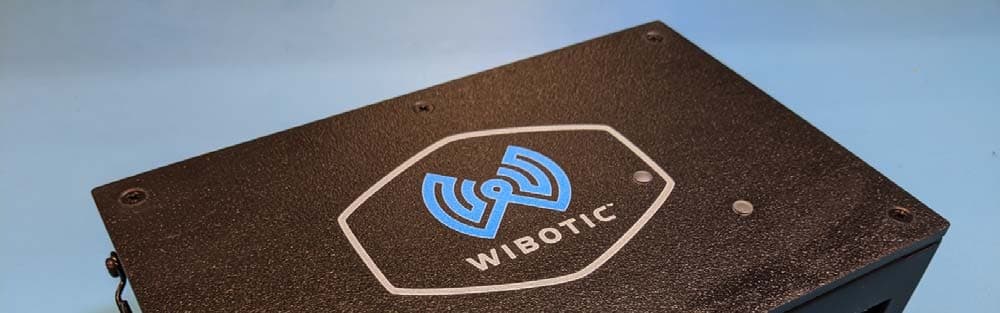
Click to zoom
Application Details
- Equipment Class
- DXT - Part 15 Low Power Transceiver, Rx Verified
- Date of Grant
- Jul 20, 2020
- Application Purpose
- Original Equipment
- Date of Application
- Jul 13, 2020
- Equipment Note
- 300W On-Board Charger
- Frequency Range
- 2433.03000000 - 2481.68000000
- Company
- Wibotic Inc.
- Country
- United States
Documents & Files
Document Text
Text extracted from the exhibit documents filed with the FCC. Open a document above to read the original.
Users Manual
Development Kit User Guide – Rev11.0 1 9706 4 th Ave NE- Suite 208 Seattle, WA 98115 206-580-09007 http://www.wibotic.com [email protected] Prepared by: WiBotic Inc Date Updated: Revision 11.0 – July 14, 2020 Notice: This document is provided for informational purposes only. It represents WiBotic’s current product offerings and practices as of the date of issue of this document, which are subject to change without notice. Customers are responsible for making their own independent assessments of the information in this document and any use of WiBotic’s products or services, each of which is provided “as is” without warranty of any kind, whether express or implied. This document does not create any warranties, representations, contractual commitments, conditions or assurances from WiBotic. © 2020, WiBotic Inc. All rights reserved. Development Kit User Guide – Rev11.0 2 Development Kit User Guide – Rev11.0 3 Contents Description ..................................................................................................................... 6 Key Features ................................................................................................................. 6 Development Kit Configuration ...................................................................................... 7 Inside the Box ................................................................................................................ 7 Specifications ................................................................................................................. 8 Power Level ................................................................................................................... 8 Initial Hardware Setup .................................................................................................. 10 Connecting the Components .................................................................................... 11 Battery Power Cable ................................................................................................ 13 Auxiliary Power Input for Onboard Charger .............................................................. 14 Configuring Ethernet Connectivity ................................................................................ 16 Windows 7/8/10 ........................................................................................................ 16 Linux (Temporary Connection) ................................................................................. 18 Linux (Permanent Connection) or Another OS ......................................................... 19 Chromebook ............................................................................................................. 19 Ethernet Configuration Reset ................................................................................... 20 Web GUI Functions...................................................................................................... 22 WiBotic Control Panel .............................................................................................. 22 “Settings” Menu ........................................................................................................ 24 Battery Settings .................................................................................................... 24 Charge Settings .................................................................................................... 28 Network Settings ................................................................................................... 30 CAN Settings ........................................................................................................ 31 “Diagnostics” Menu .................................................................................................. 31 Live Logs .............................................................................................................. 31 Version Information ............................................................................................... 32 Log Messages ...................................................................................................... 33 “Update” Menu ......................................................................................................... 33 Upload Button ....................................................................................................... 34 Development Kit User Guide – Rev11.0 4 Update Button ....................................................................................................... 35 “Data Plots” Menu .................................................................................................... 38 “About” Menu ........................................................................................................... 38 Wireless Power Transmission ...................................................................................... 39 About the Battery Charging Process......................................................................... 40 Distance Connect Mode ........................................................................................... 41 Power-Down Events ................................................................................................. 43 Troubleshooting GUI Connectivity ................................................................................ 43 Suppliers Declaration of Conformity (SDoC) ................................................................ 44 APPENDIX A: NETWORK API..................................................................................... 46 Getting Started ......................................................................................................... 46 General Packet Format ............................................................................................ 47 Request Packet Types .....................................................................................…
Text truncated - open the document above for the full version.
Cover Letter(s)
WiBotic Inc. | 9706 4th Avenue NE | Suite 208 | Seattle, WA 98115 5/12/2020 To Whom It May Concern: We hereby delegate CKC Certification Services, LLC (CKC CS) power of attorney to act on our behalf in matters pertaining to certification of products. The actions of CKC CS shall be considered the same as our own. Sincerely, Benjamin Waters CEO Wibotic, Inc.
Cover Letter(s)
WiBotic Inc. | 9706 4th Avenue NE | Suite 208 | Seattle, WA 98115 5/12/2020 Federal Communications Commission 7435 Oakland Mills Road Columbia, MD 21046 Subject: Request for Permanent Confidentiality To whom it may concern: In accordance with 47CFR Section 0.457 and Section 0.459 pertaining to confidential material, we hereby request to hold permanently confidential all information contained within the below identified exhibits/document categories submitted pursuant to radio equipment certification requirements for FCC ID: 2AVQUTR301ACST 2AVQUOC30130ST 2AVQUOC25112ST 1. Block Diagram 2. Operational Description 3. Schematics 4. Parts List / Tune-Up Procedure The above material contains trade secrets and proprietary information as specified by 47CFR 0.457(d) and technical data, which would customarily be guarded from competitors. The public disclosure of this information might be harmful to our company and provide unjustified benefits to our competitors. Sincerely, Benjamin Waters CEO Wibotic, Inc.
Cover Letter(s)
WiBotic Inc. | 9706 4 th Avenue NE | Suite 208 | Seattle, WA 98115 6/2/2020 To Whom It May Concern: I hereby appoint Benjamin Waters to sign letters and applications for any filings with regulatory agencies on our behalf, and to receive and exchange data between our company, the agents company and the agency in connection with certification for any products that our company owns or manufactures. Sincerely, Becky Schmidt Program Manager Wibotic, Inc.
Cover Letter(s)
FCC Limited Modular Approval Request – OC-301 July 6, 2020 WiBotic Inc Confidential 2020 1 7/6/2020 Federal Communications Commission Office of Engineering and Technology 7435 Oakland Mills Road Columbia, MD 21046 To Whom It May Concern: This letter is to request Limited Modular Approval in accordance with FCC Rule Part 15.212(b) for the certification request under FCC ID: 2AVQUOC30130ST. This product is a wireless power receiver and battery charger module and can be used in autonomous devices to recharge the on-board batteries. Declaration of conditions. Y/N 15.212(a)(1) Condition N (i) The radio elements of the module have their own shielding. The physical crystal and tuning capacitors may be located external to the shielded radio elements N/A (ii) The module has buffered modulation/data inputs (if such inputs are provided) to ensure that the module will comply with part 15 requirements under conditions of excessive data rates or over- modulation. Y (iii) The module has its own power supply regulation. Y (iv) The module complies with the antenna and transmission system requirements of §§15.203, 15.204(b) and 15.204(cͿ͘ The anƚenna;sͿ are eiƚher permanenƚlLJ aƚƚached or emploLJ a ͞ƵniqƵe͟ antenna coupler (at all connections between the module and the antenna, including the cable). N (v) The module was tested in a stand-alone configuration, i.e., the module was not inside another device during testing for compliance with part 15 requirements. Unless the transmitter module will be battery powered, it complies with the AC line conducted requirements found in §15.207. AC or DC power lines and data input/output lines connected to the module do not contain ferrites, unless they will be marketed with the module (see §15.27(a)). The length of these lines was the length typical of actual use or, if that length is unknown, at least 10 centimeters was used to ensure that there is no coupling between the case of the module and supporting equipment. Any accessories, peripherals, or support equipment connected to the module during testing were unmodified and commercially available (see §15.31(i)). N (vi) The module is equipped with either a permanently affixed label or is capable of electronically displaying its FCC identification number. Y (vii) The module complies with any specific rules or operating requirements that ordinarily apply to a complete transmitter and the applicant has provided adequate instructions along with the module to explain any such requirements. Y (viii) The module complies with any applicable RF exposure requirements in its final configuration. The instructions provided with the module adequately explain any usage conditions or restrictions. FCC Limited Modular Approval Request – OC-301 July 6, 2020 WiBotic Inc Confidential 2020 2 Explanation of limitations for items not compliant with the above conditions. Section Detailed Explanations (if needed) i The radio elements of the module DO NOT have their own shielding. ii The radio module is self-contained and does not have modulation or data inputs. v The radio module was tested inside a dedicated host. vi The label is placed on the enclosure of the dedicated host List of additional restrictions or conditions of use for this module (optional). Approved for used in dedicated enclosure and host Methods used to address restrictions to ensure compliance for all finished products (optional). Installation in unauthorized enclosure requires re-evaluation in the new enclosure and host. I acknowledge on behalf of the applicant that compliance of this module in all final configurations is the responsibility of the applicant under the condition that the integrator follows all provided installation instructions. Sincerely, Benjamin Waters, PhD CEO WiBotic Inc.
RF Exposure Info
Engineering RF Exposure Measurements FOR THE TR301, OC251 and OC301 Report No.: 103494-17 Date of issue: June 11, 2020 PREPARED FOR: Patrick Vilbrandt 9706 4th Ave NE, Suite 208 Seattle, WA 98115 PREPARED BY: Michael Atkinson CKC Laboratories, Inc. 5046 Sierra Pines Drive Mariposa, CA 95338 The test data contained in this report documents the observed testing parameters pertaining to and are relevant for only the sample equipment tested in the agreed upon operational mode(s) and configuration(s) as identified herein. Compliance assessment remains the client’s responsibility. This report may not be used to claim product endorsement by A2LA or any government agencies. This test report has been authorized for release under quality control from CKC Laboratories, Inc. Steve Behm Director of Quality Assurance & Engineering Services CKC Laboratories, Inc. Page 2 of 21 Report No: 103494-17 Purpose and Discussion To demonstrate compliance with United States, Canada, Australia and/or European Union RF Exposure requirements for Mobile Equipment (devices used >20cm from the body), where MPE measurements apply. Device and Antenna Operating Configuration: Device operating at maximum output power with continuous charging. Test Procedure: The EUT system consists of a transmitter module coupled with a 20 cm diameter power transmitting coil, plus a 10cm receiver coil and receiver module combination. These components are used to charge a battery wirelessly. The frequency used by the system is 6.78MHz. The manufacturer of the charging circuit brought a typical robot chassis that is used with the device, but it is not a fully assembled system, however this system limits the proximity a person could get to the charging coil when in use, so the worst case distance will be explored with the chassis in place. The manufacturer declares the charging coil is only active while charging a device via the receiver coil and receiver module. There are also several installation scenarios for the charging pad. The manufacturer declares the charging pad could either be installed into a wall, or installed into the ground, therefore, the manufacturer declares the “back” of the charging coil is inaccessible, and the investigation of worst case was not performed beyond the imagined surface that the coil would be installed onto. Essentially a semi-sphere was investigated opposite the installation case of a wall/floor surface. The EUT system was set to max power and continuously transmitting during the investigation of the worst-case H field and E field. This was done by moving the probe around the semi-sphere test volume between 20cm and 1m away from either the charging coil or as limited by the robot chassis. In this region, both the E and H fields strengths were proportional to the proximity of the charging coil. The probe was also rotated about its center in the probe XYZ axis to ensure the maximum value is reported. The worst case was found to be concentrated directly 20cm away from the edge of the charging coil. This area is able to be accessed within 20cm given the robot chassis provided by the manufacturer. This area was explored 360 degrees outside the edge of the coil, and the worst-case position was found 20cm away. This position is labeled at “20cm max.” Page 3 of 21 Report No: 103494-17 For the magnetic field, a 5-point spatial average was then performed by increasing and decreasing the height above and below the worst case point. The manufacturer declares this represents the worst-case installation situation where the charging pad is on a wall with a person next to it. Measurements were taken at 40cm above, 80cm above, 40cm below, 80cm below the “20cm max” position. Each time the probe orientation was investigated to report the maximum observed magnetic field. Finally, an investigation was performed to verify the behavior of the fields beyond 1 meter. A qualitative investigation was performed around a semi-sphere from 1 meter to beyond 3 meters and it was observed that in both the E and H field strengths were proportional the proximity of the charging coil. Measurements were collected by starting with “20cm max” and increasing the distance to 50cm, 100cm, 200cm, and 300cm to characterize the field strength behavior over distance. At each position the measurement probe was rotated in the XYZ axes to maximize the value reported. This investigation was performed on 2 different EUT systems, in both cases the transmitter was model TR301. The receiver models investigated were the OC251 and OC301. It was found that the OC301 produced slightly higher field strengths in all cases, all data presented in this report was measured using the model OC301 as representative of worst case. The following settings used by the EHP-200A software: RBW = 10kHz Span = 100kHz centered around fundamental frequency Peak values are reported. Page 4 of 21 Report No: 103494-17 Measurement Probe Information: Measurement probe used is a Narda EHP-200A. All distances recorded in this report are with respect to the center of the probe. The probe is approximately an 90mm cube, so from edge of the probe to the center in any axis is approximately 45mm. EHP-200A Internal Construction EHP-200A Dimensions Page 5 of 21 Report No: 103494-17 MPE Measurements Test Equipment Asset Description Manufacturer Model Cal Date Cal Due 03686 Field Analyzer Narda EHP-200A 4/26/2018 4/26/2021 Measurement Positions Identified below are each of the specific measurement positions. Within the areas of concern, these positions are intended to represent positions with the highest likelihood of an interference potential given typical workflow patterns and understanding of safe approach distances (2). Position* Description 20cm max The worst case 20cm position. This probe position developed the highest field values with center of probe 20 cm away from the edge of the charging coil. It was 20cm away directly off to the side of the charging coil. (see photo of orientation) 20cm ma…
Text truncated - open the document above for the full version.
Test Report
This report contains a total of 35 pages and may be reproduced in full only. Partial reproduction may only be done with the written consent of CKC Laboratories, Inc. WiBotic Inc. REVISED TEST REPORT TO 103494-5 OC-301* (*See Appendix A for Manufacturer Declaration) Tested to The Following Standards: FCC Part 15 Subpart C Section(s) 15.249 Report No.: 103494-5A Date of issue: July 13, 2020 This test report bears the accreditation symbol indicating that the testing performed herein meets the test and reporting requirements of ISO/IEC 17025 under the applicable scope of testing for CKC Laboratories, Inc. We strive to create long-term, trust based relationships by providing sound, adaptive, customer first testing services. We embrace each of our customers’ unique EMC challenges, not as an interruption to set processes, but rather as the reason we are in business. Test Certificate # 803.01 Page 2 of 35 Report No.: 103494-5A TABLE OF CONTENTS Administrative Information .......................................................................................................................... 3 Test Report Information ............................................................................................................................................ 3 Revision History ......................................................................................................................................................... 3 Report Authorization ................................................................................................................................................. 3 Test Facility Information ............................................................................................................................................ 4 Software Versions ...................................................................................................................................................... 4 Site Registration & Accreditation Information .......................................................................................................... 4 Summary of Results ................................................................................................................................................... 5 Modifications During Testing ..................................................................................................................................... 5 Conditions During Testing.......................................................................................................................................... 5 Equipment Under Test ............................................................................................................................................... 6 General Product Information..................................................................................................................................... 6 FCC Part 15 Subpart C ................................................................................................................................... 9 15.215(c) Occupied Bandwidth (20dB BW) ............................................................................................................... 9 15.249(a) Field Strength of Fundamental ................................................................................................................ 12 15.249(a) Radiated Emissions and Band Edge ......................................................................................................... 18 Appendix A: Manufacturer Declaration ...................................................................................................... 33 Supplemental Information .......................................................................................................................... 34 Measurement Uncertainty ...................................................................................................................................... 34 Emissions Test Details .............................................................................................................................................. 34 Page 3 of 35 Report No.: 103494-5A ADMINISTRATIVE INFORMATION Test Report Information REPORT PREPARED FOR: REPORT PREPARED BY: WiBotic Inc. 9706 - 4th Ave. NE Seattle, WA 98115 Darcy Thompson CKC Laboratories, Inc. 5046 Sierra Pines Drive Mariposa, CA 95338 Representative: Patrick Vilbrandt Project Number: 103494 Customer Reference Number: 1220 Rev 2 DATE OF EQUIPMENT RECEIPT: May 11, 2020 DATE(S) OF TESTING: May 11, 2020, June 3, 2020 and July 1, 2020 Revision History Original: Testing of the OC-301 to FCC Part 15 Subpart C Section(s) 15.249. Revision A: To update General Product Information Table Nominal Input Voltage from 24V battery to 60V battery. Added Configuration 2, added statement in the test sections and Conditions During test for the testing with the 60V battery. Report Authorization The test data contained in this report documents the observed testing parameters pertaining to and are relevant for only the equipment provided by the client, tested in the agreed upon operational mode(s) and configuration(s) as identified herein. Compliance assessment remains the client’s responsibility. This report may not be used to claim product endorsement by A2LA or any government agencies. This test report has been authorized for release under quality control from CKC Laboratories, Inc. Steve Behm Director of Quality Assurance & Engineering Services CKC Laboratories, Inc. Page 4 of 35 Report No.: 103494-5A Test Facility Information Our laboratories are configured to effectively test a wide variety of product types. CKC utilizes first class test equipment, anechoic chambers, data acquisition and information services to create accurate, repeatable and affordable test results. TEST LOCATION(S): CKC Laboratories, Inc. 22116 23rd Drive S.E., Suite A Canyon Park, Bothell, WA 98021 Software Versions…
Text truncated - open the document above for the full version.
Test Setup Photos
Test Setup X Axis Y Axis Z Axis Below 1GHz Above 1GHz Below 1GHz with Antenna Port Filled Below 1GHz with Antenna Port Filled Above 1GHz with Antenna Port Filled Above 1GHz with Antenna Port Filled
Contact Information
Applicant
Becky Schmidt
Technical Contact
Wibotic, inc.Patrick Vilbrandt
[email protected](206) 580-0900
9706 4th Ave NE · Seattle, Washington · United States
Test Firm
CKC Laboratories, Inc.Steve Behm
Technical Specifications
| # | Rule Parts | Frequency Range | Power Output |
|---|---|---|---|
| 1 | 15C | 2.43 GHz - 2.48 GHz | - |
Other Applications from Wibotic Inc.
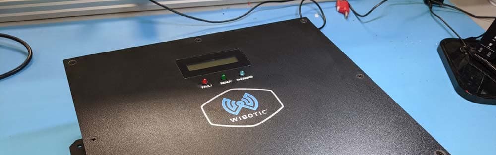
2AVQUTR301ACST
Jul 20, 2020Wireless Power Controller
Equipment Class
DXT - Part 15 Low Power Transceiver, Rx Verified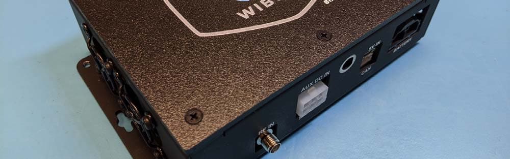
2AVQUOC25112ST
Jul 20, 2020250W On-Board Charger
Equipment Class
DXT - Part 15 Low Power Transceiver, Rx Verified