2AVWVMYZRBT001Bluetooth Module
ZHUHAI MYZR TECHNOLOGY CO., LTD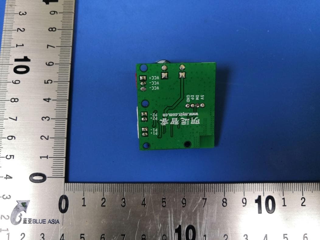
Click to zoom
Application Details
- Equipment Class
- DSS - Part 15 Spread Spectrum Transmitter
- Date of Grant
- Mar 29, 2020
- Application Purpose
- Original Equipment
- Date of Application
- Mar 29, 2020
- Equipment Note
- Bluetooth Module
- Frequency Range
- 2402.00000000 - 2480.00000000
- Country
- China
Documents & Files
Document Text
Text extracted from the exhibit documents filed with the FCC. Open a document above to read the original.
Users Manual
2.1种类 2.2型号 MY-BT_Player为我们公司的型号 Company model 3.规格 Specification MY-BT_Player产品说明书 编制/日期审核/日期批准/日期 Product pictures:Customer approval: 1. 范围 Range 2. 种类型号Types and models 外接电源蓝牙播放模块 Bluetooth player module with external power supply 2019/12/192019/12/192019/12/19 1.1 This manual is only applicable to our company's Bluetooth Player module,If you need to use it on other products,Please contact us. 1.1 这份说明书只适用于本公司的蓝牙播放模块,若需要使用到其它的产品上, 请咨询我司。 产品版本:V1客户检测: Product version:Customer test: 产品图片:客户承认: Specification 产品型号:MY-BT_Player客户型号: Product Model: Customer Model: 3.1接口规格 3.2 电源参数 Power parameter 3.3外观规格 ≈10.5g 42.1mm*37.7mm*15.5mm 工作温度 Operation temperature -25°C---+65°C MYZR 公司简写 Company abbreviation -25°C---+85°C 电源输入要求: External power supply 电源输入范围广,宽4.5V至35V输入电压范围。 Wide 4.5V to 35V Input Voltage Range 输出带载能力 Output carrying capacity 电路上采用高性能的DC/DC芯片,能够以高的速度驱动2A负 载,高效率、低纹波、出色的线路和负载调节。High performance DC/DC converter are used in the circuit.Capable of driving a 2A load with high efficiency, low ripple and excellent line and load regulation. 极数Poles2PIN OR 3PIN极数Poles2PIN 2.54mm 管脚间距Pin spacing 2.54mm 管脚间距Pin spacing 工作温度Operation temperature -25°C+85°C 工作温度Operation temperature 尺寸(mm) size 项目 item规格Specification 项目 item规格Specification 标称重量 nominal weight 外接设备 External equipment 单个板子的喇叭扬声器接口最大负载能力可以达到5W。 The maximum load capacity of the speaker interface of a single board can reach 5W. 本产品有三个外部接口,红色的为电源接口,两个白色的为喇叭接口。This product has three external interfaces, the red one is the power interface and the two white ones are the horn interface. 电源接口功放接口 颜色红色颜色白色 电源接口为XH连接器,接口为2.54MM间距,可以兼容两个管脚或三个管脚(可以 根据客户需求选定)。The power interface is an XH connector with a spacing of 2.54MM, which can be compatible with two pins or three pins (which can be selected according to customer requirements). 20191209_BT_D 时间版本号 Time 明远智睿 公司名 Company name VCC+,VCC- 电源输入 Power supply 5V、DM、DP、GND 烧录点 Burning port 4.蓝牙模式 Bluetooth mode 4.1 该模块为蓝牙语音模块,能不间断完成语音和立体声音频的无线数据传输。 4.3 蓝牙工作频率:2.402-2.480GHz 4.3 Bluetooth Operating Frequency: 2.402-2.480GHz 5.功能和操作 Functions and operations 5.3 模块符合蓝牙5.0+BR+EDR+BLE规范, 满足PowerClass2的要求,标准传输距 离达到10米。This module Compliant with Bluetooth V5.0+BR+EDR+BLE specification ,Meet the requirements of PowerClass2, and the standard transmission distance reaches 10 meters. 6.使用注意事项 6.1 电源供电需保证10W的额定供电能力,要求电源干净,纹波在 100mV左右。 www.myzr.com.cn 公司网站 Company website P1+、P1-、P2+、P2- 喇叭接口 loudspeaker Port 5.1 板子上电启动支持语音提示功能,提示音可以自主定制。When the board is connected to the power supply,The board support voice prompt function,voice prompt function can be customized independently 。 5.2 使用带蓝牙设备,打开蓝牙并搜索蓝牙,搜索到后手动连接蓝牙。连接成功 后,可使用播放器播放音乐,蓝牙名称可定制。Use a device with Bluetooth, turn on Bluetooth and search for Bluetooth, and manually connect Bluetooth after searching. After successful connection, the player can be used to play music, and the Bluetooth name can be customized. 4.2 该模块只能作为从设备模式进行工作,在该模式下的蓝牙模块,只能被主机 搜索,不能主动搜索。 外表标识 Appearance mark 4.1 This module is a Bluetooth voice module, which can continuously complete wireless data transmission of voice and stereo audio. 4.2 The module can only work as a slave device mode, and the bluetooth module in this mode can only be searched by the host and cannot be actively searched. 6.2 注意分清楚电源和喇叭接口,防止误插入导致板子损坏。 6.3 不要湿水,受潮。 6.3 Keep away from water,dampproof. 6.5 禁止将电池丢入火中或者加热器中。 6.5 Do not throw the battery into the fire or heater 6.7 禁止私自拆开板子屏蔽罩。 6.7 It is forbidden to disassemble the board shield without permission. 6.6 Do not use in the place of strong static electricity and strong magnetic field, otherwise easy to cause damage to the board or interfere with the normal use of the board. 6.4 If the board module emits an odor, generates serious heat, or the electrolytic capacitor expands or breaks, please turn off the power immediately and stop using the module 6.6 禁止在强静电和强磁场的地方使用,否则易造成板子损坏或者干扰板子的正常使用。 6.1 The rated power supply capacity of 10W shall be guaranteed for power supply, and the power supply shall be clean with a ripple of about 100mV. 6.2 Pay attention to distinguish the power supply and loudspeaker interface to prevent board damage caused by mis-insertion. 6.4 如果板子模块发出异味,发热严重,或者电解电容膨胀或者破裂,请立刻关 断电源,并停止使用该模块。 FCC Statement FCC standards: FCC CFR Title 47 Part 15 Subpart C Section 15.247 Integral antenna with antenna gain 0.5dBi This device complies with part 15 of the FCC Rules. Operation is subject to the following two conditions: (1) This device may not cause harmful interference, and (2) this device must accept any interference received, including interference that may cause undesired operation. Any Changes or modifications not expressly approved by the party responsible for compliance could void the user's authority to operate the equipment. Note: This equipment has been tested and found to comply with the limits for a Class B digital device, pursuant to part 15 of the FCC Rules. These limits are designed to provide reasonable protection against harmful interference in a residential installation. This equipment generates, uses and can radiate radio frequency energy and, if not installed and used in accordance with the instructions, may cause harmful interference to radio communications. However, there is no guarantee that interference will not occur in a particular installation. If this equipment does cause harmful interference to radio or television reception, which can be determined by turning the equipment off and on, the user is encouraged to try to correct the interference by one or more of the following measures: —Reorient or relocate the receiving antenna. —Increase the separation between the equipment and receiver. —Connect the equipment into an outlet on a circuit different from that to which the receiver is connected. —Consult the dealer or an experienced radio/TV technician for help. FCC Radiation Exposure Statement This modular complies with FCC RF radiation exposure limits set forth for an uncontrolled environment. This transmitter must not be co-…
Text truncated - open the document above for the full version.
Cover Letter(s)
DATE 2020/3/26 Equipment Autorisation Division Federal Communications Commission 7435 Oakland Mills Road Columbia, MD 21046 FCC ID: 2AVWVMYZRBT001 Product Name:Bluetooth Module Request for Confidentiality Pursuant to Sections 0.457 and 0.459 of the commission’s rules, we hereby request that the following documents be held confidential: (List here the documents for which you are seeking confidentiality – for example ...) Schematics Block diagram Operation description These materials contain trade secrets and proprietary information and are not customarily released to the public. The public disclosure of this information might be harmful to the company and provide unjustified benefits to our competitors. <Signature> Name Wang Wei Jun Title Company: ZHUHAI MYZR TECHNOLOGY CO.,LTD
Cover Letter(s)
DATE:2020/3/26 Federal Communications Commission Authorization & Evaluation Division 7345 Oakland Mills Road Columbia, Maryland 21046 On our behalf, I appoint Qianhai BlueAsia of Technical Services(Shenzhen) Co., Ltd and IOT Test Centre of BlueAsia No. 448 Bulong Road, Bantian Street, Longgang District, Shenzhen (Name of Agent preparation of this application for equipment certification. I certify that submitted documents properly describe the device or system for which equipment certification is sought. I also certify that each unit manufactured, imported or marketed, as defined in the Federal Communications Commission’s regulations will have affixed to it a label identica to that submitted for approval with this application. Forinstanceswhereourauthorizedagentsignstheapplicationforcertificationonourbehalf,Iack nowledgethatallresponsibilityforcomplyingwiththetermsandconditionsforcertification,stillres ideswith ZHUHAI MYZR TECHNOLOGY CO.,LTD Software Park Road,Zhuhai,China <Signature> Name Wang Wei Jun Title Applicant Company:ZHUHAI MYZR TECHNOLOGY CO.,LTD Federal Communications Commission Authorization & Evaluation Division Authority to Act asAgent Qianhai BlueAsia of Technical Services(Shenzhen) Co., Ltd and Test Centre of BlueAsia No. 448 Bulong Road, Bantian Street, Longgang District, Agent company name andaddress) to act as our agent in the preparation of this application for equipment certification. I certify that submitted properly describe the device or system for which equipment certification is sought. I also certify that each unit manufactured, imported or marketed, as defined in the Federal Communications Commission’s regulations will have affixed to it a label identica to that submitted for approval with this application. Forinstanceswhereourauthorizedagentsignstheapplicationforcertificationonourbehalf,Iack nowledgethatallresponsibilityforcomplyingwiththetermsandconditionsforcertification,stillres ECHNOLOGY CO.,LTD,Floor 3,Area B2 National Hi-tech Zone China (Applicant Nameandaddress) HUHAI MYZR TECHNOLOGY CO.,LTD Qianhai BlueAsia of Technical Services(Shenzhen) Co., Ltd and Test Centre of BlueAsia No. 448 Bulong Road, Bantian Street, Longgang District, address) to act as our agent in the preparation of this application for equipment certification. I certify that submitted properly describe the device or system for which equipment certification is sought. I also certify that each unit manufactured, imported or marketed, as defined in the Federal Communications Commission’s regulations will have affixed to it a label identical Forinstanceswhereourauthorizedagentsignstheapplicationforcertificationonourbehalf,Iack nowledgethatallresponsibilityforcomplyingwiththetermsandconditionsforcertification,stillres tech Zone,No.1
Cover Letter(s)
Single Modular Approval Declaration Letter We ,ZHUHAI MYZR TECHNOLOGY CO.,LTD apply Single modular approval for Product Name: Bluetooth Module Model: MY-BT_Player , MY-Bluetooth FCC ID: 2AVWVMYZRBT001 According to 996369 D01 Module Equip Auth Guide v01r04 and 15.212 requirement: 1) The radio elements must have the radio frequency circuitry shielded. Physical components and tuning capacitor(s) may be located external to the shield, but must be on the module assembly; Answer :Yes , Shielding for both side . 2) The module must have buffered modulation/data inputs to ensure that the device willcomply with Part 15 requirements with any type of input signal; Answer :Yes, All inputs to the modules are buffered through logic or microprocessor inputs. 3)The modular transmitter must have its own power supply regulation. Answer :Yes, A low drop out regulator is used for modular power supply regulation. 4) The module must contain a permanently attached antenna, or contain a unique antennaconnector, and be marketed and operated only with specific antenna(s), per Sections15.203, 15.204(b), 15.204(c), 15.212(a), 2.929(b); Answer :Yes, Device is equipped with Chip antenna. (5) The module must demonstrate compliance in a stand-alone configuration; Answer :Yes, Distance between modular and all AEs are bigger than 10cm ,refer to setup photo. (6) The module must be labeled with its permanently affixed FCC ID label, or use an electronic display (See KDB Publication 784748 about labeling requirements); Answer :Yes, The modular has a permanent fixed label, and below statement was listed in the User Manual; The host device must be labeled to display the FCC ID of the module “Contains FCC ID: 2AVWVMYZRBT001” (7) The module must comply with all specific rules applicable to the transmitter includingall the conditions provided in the integration instructions by the grantee; Answer :Yes ,The module comply with all specific rules applicable to the transmitter including all the conditions provided in the integration instructions by the grantee, Refer to test report and user manual . (8) The module must comply with RF exposure requirements Answer :Yes ,Transmitter meets MPE calculation of 47 CFR 1.1307 . Refer to MPE Reports and Refer to modular installation manual. Model: MY-BT_Player , MY-Bluetooth, All above models are identical in the same PCB layout, interior structure and electrical circuits. The differences are model name for commercial purpose. Please contact me if you have any further questions. Thanks for your attention. Best Regards, <Signature> Name Wang Wei Jun Company: ZHUHAI MYZR TECHNOLOGY CO.,LTD
Cover Letter(s)
Compliance list INTEGRATION INSTRUCTIONS for 996369 D03 OEM the and 996369 D03 OEM by Sections 2.2 through 2.10. Requirement Yes N/A Comment 2.2 List of applicable FCC rules List the FCC rules that are applicable to the modular transmitter. These are the rules that specifically establish the bands of operation, the power, spurious emissions, and operating fundamental frequencies. DO NOT list compliance to unintentional-radiator rules (Part 15 Subpart B) since that is not a condition of a module grant that is extended to a host manufacturer. See also Section 2.10 below concerning the need to notify host manufacturers that further testing is required.3 YES Refer to instruction FCC standards: FCC CFR Title 47 Part 15 Subpart C Section 15.247 2.3 Summarize the specific operational use conditions Describe use conditions that are applicable to the modular transmitter, including for example any limits on antennas, etc. For example, if point-to-point antennas are used that require reduction in power or compensation for cable loss, then this information must be in the instructions. If the use condition limitations extend to professional users, then instructions must state that this information also extends to the host manufacturer’s instruction manual. In addition, certain information may also be needed, such as peak gain per frequency band and minimum gain, specifically for master devices in 5 GHz DFS bands. YES Refer to instruction Integral antenna with antenna gain 0.5dBi 2.4 Limited module procedures If a modular transmitter is approved as a “limited module,” then the module manufacturer is responsible for approving the host environment that the limited module is used with. The manufacturer of a limited module must describe, both in the filing and in the installation instructions, the alternative means that the limited module manufacturer uses to verify that the host meets the necessary requirements to satisfy the module limiting conditions. A limited module manufacturer has the flexibility to define its alternative method to address the conditions that limit the initial approval, such as: shielding, minimum N/A Not applicable signaling amplitude, buffered modulation/data inputs, or power supply regulation. The alternative method could include that the limited module manufacturer reviews detailed test data or host designs prior to giving the host manufacturer approval. This limited module procedure is also applicable for RF exposure evaluation when it is necessary to demonstrate compliance in a specific host. The module manufacturer must state how control of the product into which the modular transmitter will be installed will be maintained such that full compliance of the product is always ensured. For additional hosts other than the specific host originally granted with a limited module, a Class II permissive change is required on the module grant to register the additional host as a specific host also approved with the module. 2.5 Trace antenna designs For a modular transmitter with trace antenna designs, see the guidance in Question 11 of KDB Publication 996369 D02 FAQ – Modules for Micro-Strip Antennas and traces. The integration information shall include for the TCB review the integration instructions for the following aspects: layout of trace design, parts list (BOM), antenna, connectors, and isolation requirements. 4 a) Information that includes permitted variances (e.g., trace boundary limits, thickness, length, width, shape(s), dielectric constant, and impedance as applicable for each type of antenna); b) Each design shall be considered a different type (e.g., antenna length in multiple(s) of frequency, the wavelength, and antenna shape (traces in phase) can affect antenna gain and must be considered); c) The parameters shall be provided in a manner permitting host manufacturers to design the printed circuit (PC) board layout; d) Appropriate parts by manufacturer and specifications; e) Test procedures for design verification; and N/A Not applicable f) Production test procedures for ensuring compliance. The module grantee shall provide a notice that any deviation(s) from the defined parameters of the antenna trace, as described by the instructions, require that the host product manufacturer must notify the module grantee that they wish to change the antenna trace design. In this case, a Class II permissive change application is required to be filed by the grantee, or the host manufacturer can take responsibility through the change in FCC ID (new application) procedure followed by a Class II permissive change application. 2.6 RF exposure considerations It is essential for module grantees to clearly and explicitly state the RF exposure conditions that permit a host product manufacturer to use the module. Two types of instructions are required for RF exposure information: (1) to the host product manufacturer, to define the application conditions (mobile, portable – xx cm from a person’s body); and (2) additional text needed for the host product manufacturer to provide to end users in their end-product manuals. If RF exposure statements and use conditions are not provided, then the host product manufacturer is required to take responsibility of the module through a change in FCC ID (new application). YES Refer to instruction This modular complies with FCC RF radiation exposure limits set forth for an uncontrolled environment. This transmitter must not be co-located or operating in conjunction with any other antenna or transmitter. 2.7 Antennas A list of antennas included in the application for certification must be provided in the instructions. For modular transmitters approved as limited modules, all applicable professional installer instructions must be included as part of the information to the host product manufacturer. The antenna list shall also identify the antenna types (monopole, PIFA, dipole, etc. (note that for example an “omni-directional antenna” is not considered to be a sp…
Text truncated - open the document above for the full version.
External Photos
Model No.: MY-BT_Player
Internal Photos
Model No.: MY-BT_Player
RF Exposure Info
Page 1 of 2 RF Exposure Evaluation Report 1 RF EXPOSURE Product Name Bluetooth Module Model No. MY-BT_Player, MY-Bluetooth FCC ID 2AVWVMYZRBT001 1.1 LIMITS The 1-g and 10-g SAR test exclusion thresholds for 100 MHz to 6 GHz at test separation distances ≤ 50 mm are determined by: [(max. power of channel, including tune-up tolerance, mW) / (min. test separation distance, mm)] · [√f(GHz)] ≤ 3.0 for 1-g SAR and ≤ 7.5 for 10-g extremity SAR, where f(GHz) is the RF channel transmit frequency in GHz Power and distance are rounded to the nearest mW and mm before calculation 17 The result is rounded to one decimal place for comparison The test exclusions are applicable only when the minimum test separation distance is ≤ 50 mm and for transmission frequencies between 100 MHz and 6 GHz. When the minimum test separation distance is < 5 mm, a distance of 5 mm is applied to determine SAR test exclusion Page 2 of 2 1.2 EUT RF EXPOSURE EVALUATION Operational Mode: EDR (pi/4DQPSK worst case) Channel Maximum Peak Conducted Output Power (dBm) Tune up tolerance (dB) Maximum tune-up Power Calculated value Exclusion threshold (dBm) (mW) 2402MHZ 3.61 ±1 4.61 2.89 0.90 3.0 2441MHz 3.54 ±1 4.54 2.84 0.89 2480MHz 3.46 ±1 4.46 2.79 0.88 Operational Mode: BLE 3.0 2402 MHZ 2.98 ±1 3.98 2.50 0.78 2442 MHZ 3.01 ±1 4.01 2.52 0.79 2480 MHZ 2.83 ±1 3.83 2.42 0.76 Conclusion: the calculated value ≤3.0, SAR is exempted.
Test Report
Page 1 of77 TEST REPORT Product Name : Bluetooth Module Brand Mark : MYZR Model No. : MY-BT_Player, MY-Bluetooth FCC ID : 2AVWVMYZRBT001 Report Number : BLA-EMC-202003-A1601 Date of Sample Receipt : 2020/3/12 Date of Test : 2020/3/20 to 2020/3/25 Date of Issue : 2020/3/25 Test Standard : 47 CFR Part 15, Subpart C 15.247 Test Result : Pass Prepared for: ZHUHAI MYZR TECHNOLOGY CO.,LTD Floor 3, Area B2 National Hi-tech Zone, No.1 Software Park Road, Zhuhai, China Prepared by: BlueAsia of Technical Services(Shenzhen) Co.,Ltd. IOT Test Centre of BlueAsia No. 448 Bulong Road, Bantian Street, Longgang District, Shenzhen, China TEL: +86-755-28682673 FAX: +86-755-28682673 Compiled by: Review by: Approved by: Date: 2020/3/25 Report No.: BLA-EMC-202003-A1601 Page 2 of77 REPORT REVISE RECORD Version No. Date Description 00 2020/3/25 Original Report No.: BLA-EMC-202003-A1601 Page 3 of77 TABLE OF CONTENTS 1 TEST SUMMARY ........................................................................................................................................6 2 GENERAL INFORMATION .........................................................................................................................7 3 GENERAL DESCRIPTION OF E.U.T. .........................................................................................................7 4 TEST ENVIRONMENT ................................................................................................................................8 5 TEST MODE ................................................................................................................................................8 6 MEASUREMENT UNCERTAINTY ..............................................................................................................8 7 DESCRIPTION OF SUPPORT UNIT...........................................................................................................9 8 LABORATORY LOCATION .........................................................................................................................9 9 TEST INSTRUMENTS LIST ..................................................................................................................... 10 RADIATED SPURIOUS EMISSIONS ............................................................................................................... 14 LIMITS ............................................................................................................................................................................. 14 BLOCK DIAGRAM OF TEST SETUP .................................................................................................................................... 14 PROCEDURE ................................................................................................................................................................... 15 TEST DATA ........................................................................................................................................................................ 17 RADIATED EMISSIONS WHICH FALL IN THE RESTRICTED BANDS ......................................................... 22 LIMITS ............................................................................................................................................................................. 22 BLOCK DIAGRAM OF TEST SETUP .................................................................................................................................... 23 PROCEDURE ................................................................................................................................................................... 23 TEST DATA ........................................................................................................................................................................ 24 ANTENNA REQUIREMENT .............................................................................................................................. 26 CONCLUSION ...................................................................................................................................................................... 26 CONDUCTED BAND EDGES MEASUREMENT ............................................................................................. 27 LIMITS ............................................................................................................................................................................. 27 BLOCK DIAGRAM OF TEST SETUP .................................................................................................................................... 27 TEST DATA ........................................................................................................................................................................ 28 CONDUCTED SPURIOUS EMISSIONS ........................................................................................................... 29 LIMITS ............................................................................................................................................................................. 29 BLOCK DIAGRAM OF TEST SETUP .................................................................................................................................... 29 TEST DATA ........................................................................................................................................................................ 30 Report No.: BLA-EMC-202003-A1601 Page 4 of77 DWELL TIME..................................................................................................................................................... 31 LIMITS ............................................................................................................................................................................. 31 BLOCK DIAGRAM OF TEST SETUP ................................…
Text truncated - open the document above for the full version.
Test Report
Report No.: BLA-EMC-202003-A1601 Page 41 of77 [Test Mode: TX]; [Line: Nutral] Test Result: Pass Report No.: BLA-EMC-202003-A1601 Page 42 of77 10 APPENDIX Appendix1 10.1 APPENDIX: 20DBEMISSION BANDWIDTH Test Result TestMode Antenna Channel 20dB EBW[MHz] FL[MHz] FH[MHz] Limit[MHz] Verdict DH1Ant1 24021.0802401.3942402.474---PASS 2441 1.077 2440.397 2441.474 --- PASS 24801.0832479.3912480.474---PASS 2DH1Ant1 2402 1.371 2401.247 2402.618 --- PASS 2441 1.374 2440.244 2441.618 --- PASS 24801.3682479.2442480.612---PASS Report No.: BLA-EMC-202003-A1601 Page 43 of77 Test Graphs DH1_Ant1_2402 DH1_Ant1_2441 DH1_Ant1_2480 Report No.: BLA-EMC-202003-A1601 Page 44 of77 2DH1_Ant1_2402 2DH1_Ant1_2441 Report No.: BLA-EMC-202003-A1601 Page 45 of77 2DH1_Ant1_2480 Report No.: BLA-EMC-202003-A1601 Page 46 of77 10.2 APPENDIX: MAXIMUM CONDUCTED OUTPUT POWER Test Result TestMode Antenna Channel Result[dBm] Limit[dBm] Verdict DH1 Ant1 2402 2.97 <=20.97 PASS 2441 3.03 <=20.97 PASS 2480 2.86 <=20.97 PASS 2DH1 Ant1 2402 3.61 <=20.97 PASS 2441 3.54 <=20.97 PASS 2480 3.46 <=20.97 PASS Report No.: BLA-EMC-202003-A1601 Page 47 of77 Test Graphs DH1_Ant1_2402 DH1_Ant1_2441 DH1_Ant1_2480 Report No.: BLA-EMC-202003-A1601 Page 48 of77 2DH1_Ant1_2402 2DH1_Ant1_2441 Report No.: BLA-EMC-202003-A1601 Page 49 of77 2DH1_Ant1_2480 Report No.: BLA-EMC-202003-A1601 Page 50 of77 10.3 APPENDIX: CARRIER FREQUENCY SEPARATION Test Result TestMode Antenna Channel Result[MHz] Limit[MHz] Verdict DH1 Ant1 Hop 1.008 >=0.722 PASS 2DH1 Ant1 Hop 0.98 >=0.916 PASS Report No.: BLA-EMC-202003-A1601 Page 51 of77 Test Graphs DH1_Ant1_Hop 2DH1_Ant1_Hop Report No.: BLA-EMC-202003-A1601 Page 52 of77 10.4 APPENDIX: TIME OF OCCUPANCY Test Result TestMode Antenna Channel BurstWidth [ms] TotalHops [Num] Result[s] Limit[s] Verdict DH1 Ant1 Hop 0.37 330 0.124 <=0.4 PASS DH3 Ant1 Hop 1.63 160 0.261 <=0.4 PASS DH5 Ant1 Hop 2.88 120 0.345 <=0.4 PASS Report No.: BLA-EMC-202003-A1601 Page 53 of77 Test Graphs DH1_Ant1_Hop DH3_Ant1_Hop Report No.: BLA-EMC-202003-A1601 Page 54 of77 DH5_Ant1_Hop Report No.: BLA-EMC-202003-A1601 Page 55 of77 Report No.: BLA-EMC-202003-A1601 Page 56 of77 10.5 APPENDIX: NUMBER OF HOPPING CHANNELS Test Result TestMode Antenna Channel Result[Num] Limit[Num] Verdict DH1 Ant1 Hop 79 >=15 PASS 2DH1 Ant1 Hop 79 >=15 PASS Report No.: BLA-EMC-202003-A1601 Page 57 of77 Test Graphs DH1_Ant1_Hop 2DH1_Ant1_Hop Report No.: BLA-EMC-202003-A1601 Page 58 of77 10.6 APPENDIX:BAND EDGE MEASUREMENTS Test Result TestMode Antenna ChName Channel RefLevel [dBm] Result [dBm] Limit [dBm] Verdict DH1 Ant1 Low 2402 2.64 -51.95 <=-17.36 PASS High 2480 2.56 -51.64 <=-17.44 PASS Low Hop_2402 2.62 -53.54 -17.38 PASS High Hop_2480 2.63 -49.92 -17.37 PASS 2DH1 Ant1 Low 2402 2.66 -49.01 <=-17.35 PASS High 2480 2.55 -52.67 <=-17.45 PASS Low Hop_2402 2.74 -53.29 -17.26 PASS High Hop_2480 2.58 -52.41 -17.42 PASS Report No.: BLA-EMC-202003-A1601 Page 59 of77 Test Graphs DH1_Ant1_Low_2402 DH1_Ant1_High_2480 DH1_Ant1_Low_Hop_2402 Report No.: BLA-EMC-202003-A1601 Page 60 of77 DH1_Ant1_High_Hop_2480 2DH1_Ant1_Low_2402 Report No.: BLA-EMC-202003-A1601 Page 61 of77 2DH1_Ant1_High_2480 2DH1_Ant1_Low_Hop_2402 Report No.: BLA-EMC-202003-A1601 Page 62 of77 2DH1_Ant1_High_Hop_2480 Report No.: BLA-EMC-202003-A1601 Page 63 of77 10.7 APPENDIX:CONDUCTED SPURIOUSEMISSION Test Result TestMode Antenna Channel FreqRange [MHz] RefLevel [dBm] Result [dBm] Limit [dBm] Verdict DH1 Ant1 2402 Reference 2.52 2.52 --- PASS 30~1000 30~1000 -66.79 <=-17.478 PASS 1000~26500 1000~26500 -37.667 <=-17.478 PASS 2441 Reference 2.63 2.63 --- PASS 30~1000 30~1000 -66.997 <=-17.375 PASS 1000~26500 1000~26500 -36.198 <=-17.375 PASS 2480 Reference 1.81 1.81 --- PASS 30~1000 30~1000 -67.309 <=-18.189 PASS 1000~26500 1000~26500 -39.619 <=-18.189 PASS 2DH1 Ant1 2402 Reference 2.64 2.64 --- PASS 30~1000 30~1000 -67.12 <=-17.356 PASS 1000~26500 1000~26500 -35.728 <=-17.356 PASS 2441 Reference 2.42 2.42 --- PASS 30~1000 30~1000 -68.381 <=-17.581 PASS 1000~26500 1000~26500 -35.69 <=-17.581 PASS 2480 Reference 2.51 2.51 --- PASS 30~1000 30~1000 -67.147 <=-17.487 PASS 1000~26500 1000~26500 -40.183 <=-17.487 PASS Report No.: BLA-EMC-202003-A1601 Page 64 of77 Test Graphs DH1_Ant1_2402_0~Reference DH1_Ant1_2402_30~1000 DH1_Ant1_2402_1000~26500 Report No.: BLA-EMC-202003-A1601 Page 65 of77 DH1_Ant1_2441_0~…
Text truncated - open the document above for the full version.
Contact Information
Applicant
Wei Jun Wang(Manager)
Test Firm
BlueAsia of Technical Services (Shenzhen)Blue Zheng
[email protected]+86 755-23059481-815
Technical Specifications
| # | Rule Parts | Frequency Range | Power Output |
|---|---|---|---|
| 1 | 15C | 2.40 GHz - 2.48 GHz | 2.30 mW |