2AVXA-SGHunting Light Remote Control
Murray Hunting LLC: DBA Slow Glow Hunting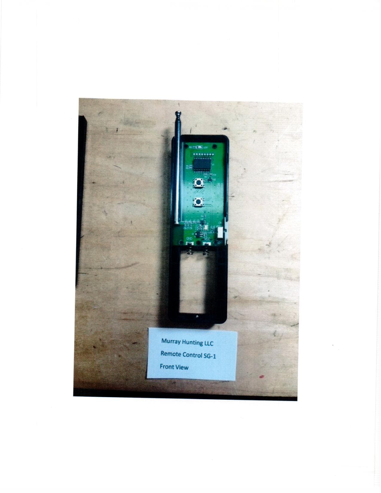
Click to zoom
Application Details
- Equipment Class
- DSC - Part 15 Security/Remote Control Transmitter
- Date of Grant
- Sep 23, 2020
- Application Purpose
- Original Equipment
- Date of Application
- Sep 23, 2020
- Equipment Note
- Hunting Light Remote Control
- Frequency Range
- 433.92000000 - 433.92000000
- Country
- United States
Documents & Files
Document Text
Text extracted from the exhibit documents filed with the FCC. Open a document above to read the original.
Users Manual
USER MANUAL & OPERATING INSTRUCTIONS L.E.D. HUNTING LIGHTS slow glow The Slow Glow Gradual Illuminant Technology Hunting light system is the most advanced hunting light ever made. Simply connect your battery and walk away; there are no switches or settings to make. Your light will stay off during the day and automatically come on at dusk. For efficiency, a sophisticated brightness control circuit wi will constantly look for motion and adjust the LED intensity automatically. When triggered by motion, the intensity of your light will slowly illuminate the hunting area which eliminates sudden flashes or startling changes in light. This unique stealth technology was designed for ease of use and fail-safe dependability. Our Our Tag-Line: “They’ll Never Know What Lit ‘em” will be evident the first time you use your new Slow Glow. No other light creates a hunting experiences like this! SLOW GLOW TECHNOLOGY Slow Glow LED Lights Page 3 Slow Glow Light Packages Page 4 Powering Your Light Page 5 Changing Light Color Page 6 Modes of Operation Page 7 Reversing the Lens Page 9 Light Functions Light Functions Page 10 Mounting Your Light Page 11 Building Your Stealth Box Page 13 Installing Your Solar Panel Page 15 Troubleshooting Page 16 Light Specifications Page 17 Warranty Information Page 18 “How to Hunt Slow Glow” “How to Hunt Slow Glow” Back Page www.SlowGlow.com TABLE OF CONTENTS PAGE 3 The Slow Glow model IRG is the evolution of the Slow Glow Family of Lights. Our IRG model features all the same attributes of our signature RMT, but adds the ability to cast infrared light (instead of visible red). When utilizing Green Light, your IRG will act exactly l like our model RMT. When you switch to Infrared, light functions change slightly. Because there is no visible light, there is no Model: IRG The Slow Glow model RMT is our signature light. “RMT” stands for Remote, Motion, & Training. Training Mode keeps your light at just 5% intensity all night until motion is detected; this trains game to a non-invasive dull light in the area. Motion Triggers our Gradual I Gradual Illuminant Technology which brings your light to 60% intensity over a 2-minute period, and the included remote control allows you to control your light from more than 100 yards away. Model: RMT SLOW GLOW LIGHTS The “All In One” package comes with our signature RMT or IRG hunting light, packaged in our Stealth Box Setup (with all the same accessories as our Stealth Box Package), AND includes a 12v battery, 5w Solar Panel, and mounting hardware for your solar panel to the top of a t-post. top of a t-post. SLOW GLOW PACKAGES PAGE 4 PAGE 5 POWERING UNIT ON / OFF Light within a Stealth Box Lights that came as part of our Stealth Box package have a shorter power-cord with a male barrel plug. Simply plug the light into either the RED or GREEN power jack barrel, and ensure the barrels a are connected to the correct battery terminals. Model IRG Lights activate 850nm infrared light when utilizing the RED barrel, and green LED light when connected to the GREEN barrel. We offer an optional 5’ extension cord that can be purchased on our website. This a allows you to mount your Slow Glow out- side of your Stealthbox, with enough cord to set your battery on the ground. Light without a Stealth Box If you ordered a light without the optional Stealth Box, your light will have a 5’ power cord with Red & Black quick-connect terminals. If you desire a RED light, hook the Slow Glow power cord directly to the ba battery with the red wire going to the positive terminal and the black wire going to the negative terminal. If you desire a GREEN light, reverse the polarity and hook up the red wire to the negative terminal and the black wire to the red terminal of the battery. CHANGING LIGHT COLOR PAGE 6 Mode 2: TRAINING MODE (5% light output) Training mode is activated at dusk and will produce a very efficient dim glow (5% intensity), training game to a light in the area. Your light will stay lit in training mode the entire night at this faint 5% glow to introduce non-intrusive light to your hunting area. Your light will remain in training mode until motion is detected or triggered with the r remote control. Training mode is not bright enough to be intimidating to most game, and commonly goes unnoticed by wild hogs, exotic game, and predators. The longer a light is left in a hunting area, the more accustom game become to the light. Model IRG: If your model IRG light is in Infrared mode, it will continue to utilize training mode 5% light output. Even though the light is not visible, it allows the hunter to monitor the area using night vision wi without activating the light up to 100% by remote control. Mode 1: DAYTIME MODE (0% light output) Two independent monitoring eyes constantly evaluate ambient light conditions; both sensors require ample natural light to activate the light to turn on. This prevents unintended dimming during full moon conditions or when hunting near bright backlit areas. This feature also allows the Slow Glow system to function at post-dawn and pre-dusk periods (prime periods (prime time for nocturnal game). Daytime Mode (0%) uses no battery power and is activated shortly after daylight. 4 MODES OF OPERATION PAGE 7 *Model IRG Lights: If your model IRG light is in GREEN mode, it will utilize the Gradual Illuminant Technology and increase light slowly. If your model IRG is in infrared mode, the gradual light increase has been omitted and will increase to 60% immediately after detecting motion, and 100% after pressing the remote control FULL button. Mode 4: REMOTE CONTROL MODE (100% light output) The remote control can be used to increase the intensity of your light to 100%; remote control mode will also latch the system in the full-on mode to prevent system from dimming, regardless of detected motion. This feature should be used when stalking in behind your light. Due to the amount of battery power required for Remote Control Mode (100% intensity), …
Text truncated - open the document above for the full version.
Test Report
HEADQUARTERS: 914 WEST PATAPSCO AVENUE • BALTIMORE, MARYLAND 21230 • PHONE (410) 354-3300 • FAX (410) 354-3313 Maryland | California | Texas www.metlabs.com September 23, 2020 Murray Hunting LLC 1070 County Road 279 Liberty Hill, TX 78642 Dear Mr. Murray Choate, Enclosed is the EMC Wireless test report for compliance testing of the Murray Hunting LLC, Remote Control SG-1 as tested to the requirements of Title 47 of the CFR, Ch. 1 (10-1-06 ed.), FCC Part 15 Subpart C for Intentional Radiators. Thank you for using the services of Eurofins E&E North America. If you have any questions regarding these results or if we can be of further service to you, please feel free to contact me. Sincerely yours, EUROFINS E&E NORTH AMERICA Michelle Tawmging Documentation Department Reference: (\Murray Hunting LLC\WIRA102180-FCC231 Rev. 1) Certificates and reports shall not be reproduced except in full, without the written permission of Eurofins E&E North America. This letter of transmittal is not a part of the attached report. Eurofins MET Laboratories Inc. (Eurofins E&E North America) is part of the Eurofins Electrical & Electronics (E&E) global compliance network. HEADQUARTERS: 914 WEST PATAPSCO AVENUE • BALTIMORE, MARYLAND 21230 • PHONE (410) 354-3300 • FAX (410) 354-3313 Report: WIRA102180-FCC231 Rev. 1 © 2020, Eurofins E&E North America Page ii of vii Electromagnetic Compatibility Criteria Test Report for the Murray Hunting LLC Remote Control Tested under the FCC Certification Rules contained in Title 47 of the CFR, Part 15.231 Subpart C for Intentional Radiators Report: WIRA102180-FCC231 Rev. 1 September 23, 2020 Prepared For: Murray Hunting LLC 1070 County Road 279 Liberty Hill, TX 78642 Prepared By: Eurofins E&E North America 13501 McCallen Pass, Austin, TX 78753 Murray Hunting LLC Hog Hunting Light Report: WIRA102180-FCC231 Rev. 1 © 2020, Eurofins E&E North America Page iii of vii Electromagnetic Compatibility Criteria Test Report for the Murray Hunting LLC Remote Control Tested under the FCC Certification Rules contained in Title 47 of the CFR, Part 15.231 Subpart C for Intentional Radiators Report: WIRA102180-FCC231 September 23, 2020 Adan Arab, Project Engineer Michelle Tawmging Electromagnetic Compatibility Lab Documentation Department Engineering Statement: The measurements shown in this report were made in accordance with the procedures indicated, and the emissions from this equipment were found to be within the limits applicable. I assume full responsibility for the accuracy and completeness of these measurements, and for the qualifications of all persons taking them. It is further stated that upon the basis of the measurements made, the equipment tested is capable of operation in accordance with the requirements of FCC Rules Part 15.231 under normal use and maintenance. Jonathan Tavira Manager, Electromagnetic Compatibility Lab Murray Hunting LLC Hog Hunting Light Report: WIRA102180-FCC231 Rev. 1 © 2020, Eurofins E&E North America Page iv of vii Report Status Sheet Revision Report Date Reason for Revision August 24, 2020 Initial Issue. 1 September 23, 2020 TCB Comments. Murray Hunting LLC Hog Hunting Light Report: WIRA102180-FCC231 Rev. 1 © 2020, Eurofins E&E North America Page v of vii Table of Contents I. Executive Summary ...................................................................................................................................... 1 A. Purpose of Test ......................................................................................................................................... 2 B. Executive Summary ................................................................................................................................. 2 II. Equipment Configuration ............................................................................................................................. 3 A. Overview .................................................................................................................................................. 4 B. References ................................................................................................................................................ 4 C. Test Site.................................................................................................................................................... 5 D. Measurement Uncertainty ........................................................................................................................ 5 E. Description of Test Sample ...................................................................................................................... 5 F. Equipment Configuration ......................................................................................................................... 6 G. Support Equipment ................................................................................................................................... 6 H. Ports and Cabling Information ................................................................................................................. 6 I. Mode of Operation ................................................................................................................................... 6 J. Monitoring Method .................................................................................................................................. 6 K. Modifications ........................................................................................................................................... 6 a) Modifications to EUT ......................................................................................................... 6 b) Modifications to Test Standard ........................................................................................... 6 L. Disposition of EUT .......................................................................................................................…
Text truncated - open the document above for the full version.
Test Setup Photos
Figure 1: Remote Control - RSE - 1-5 GHz - Setup Antenna View Figure 2: Remote Control - RSE - 1-5 GHz - Setup Front View Figure 3: Remote Control - RSE - 1-5 GHz - Setup Rear View Figure 4: Remote Control - RSE - 30-1000 MHz - Setup Antenna View Figure 5: Remote Control - RSE - 30-1000 MHz - Setup Front View Figure 6: Remote Control - RSE - 30-1000 MHz - Setup Rear View
Contact Information
Applicant
Murray Kent Choate(Owner/CEO)
Technical Contact
Murray Hunting LLC, DBA Slow Glow HuntingMurray Choate
[email protected]512-560-9123
1070 CR 279 · Liberty Hill, Texas · United States
Test Firm
EUROFINS ELECTRICAL AND ELECTRONIC TESTING NA, INCGreg Kovolenko
Technical Specifications
| # | Rule Parts | Frequency Range | Power Output |
|---|---|---|---|
| 1 | 15.231 | 433.92 MHz - 433.92 MHz | - |