2AVXUS-003WRC TOYS with 2.4G function
CHENGHAI XINDONGLI PLASTIC TOYS FACTORY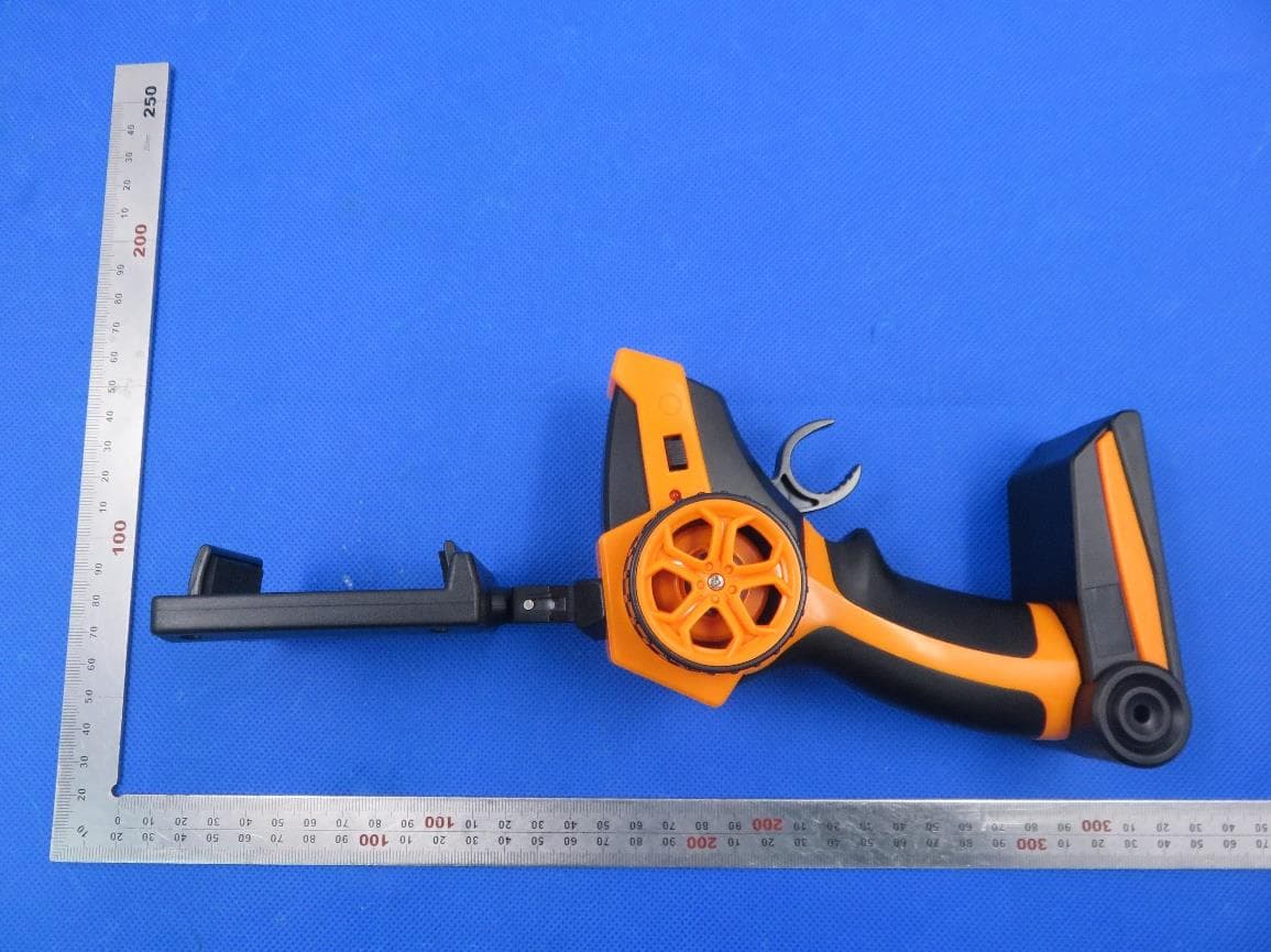
Click to zoom
Application Details
- Equipment Class
- DXX - Part 15 Low Power Communication Device Transmitter
- Date of Grant
- Apr 13, 2020
- Application Purpose
- Original Equipment
- Date of Application
- Apr 13, 2020
- Equipment Note
- RC TOYS with 2.4G function
- Frequency Range
- 2420.00000000 - 2465.00000000
- Country
- China
Documents & Files
Document Text
Text extracted from the exhibit documents filed with the FCC. Open a document above to read the original.
Users Manual
1 INSTRUCTION MANUAL: SPY ROVER MINI8+ NOTE: This equipment has been tested and found to comply with the limits for a Class B digital device, pursuant to part 15 of the FCC Rules. These limits are designed to provide reasonable protection against harmful interference in a residential installation. This equipment generates uses and can radiate radio frequency energy and, if not installed and used in accordance with the instructions, may cause harmful interference to radio communications. However, there is no guarantee that interference will not occur in a particular installation. If this equipment does cause harmful interference to radio or television reception, which can be determined by turning the equipment off and on, the user is encouraged to try to correct the interference by one or more of the following measures: - Reorient or relocate the receiving antenna. - Increase the separation between the equipment and receiver. - Connect the equipment into an outlet on a circuit different from that to which the receiver is connected. - Consult the dealer or an experienced radio/TV technician for help Changes or modifications not expressly approved by the party responsible for compliance could void the user's authority to operate the equipment. This device complies with Part 15 of the FCC Rules. Operation is subject to the following two conditions: (1) this device may not cause harmful interference, and (2) this device must accept any interference received, including interference that may cause undesired operation. SETTING UP THE SPY ROVER MINI SETTING UP THE REMOTE CONTROL 1. Turn off the power switch. 2. Using a phillips screwdriver open the battery compartment. 3. Connect the battery wire to the Spy Rover Mini’s connector as shown on the diagram. 4. Close the battery compartment and switch the power switch to On. FOR AGES 1. Using a phillips screwdriver open the batt ery cover on the base of the controller. 2. Install 2x new AA batt eries taking care to match the correct polarity (+/-). 3. Close the batt ery cover. Power Switch AA Batt eries 4 CARE & MAINTENANCE NOT FOLLOWING THESE PRECAUTIONS WILL VOID YOUR WARRANTY CAUTIONS & WARNINGS • Suitable for ages 8 and up. Adult supervision is always recommended. • This product contains small parts which are a choking hazard. Keep away from small children. • Manufacturers and dealers disclaim all responsibility for damage caused by misuse. • Keep hair and loose clothing away from the Spy Rover Mini when powered on. • If Spy Rover Mini will be stored and unused for an extended period of time, please remove the batteries. • Check the batteries regularly for potential leakage or corrosion that may occur. • When installing the batteries carefully follow the polarity marking +/-. • Do not mix different battery types. • Remove exhausted or drained batteries. • Do not exceed charging volts and amps of 5v1a. • Do not leave charger connected or charge for more than 1hr. • Do not submerge the unit in any liquids. • Keep the unit dry. • Do not place the unit near powerful, un-shielded magnets. • Do not expose the unit to extreme hot or cold temperatures. • Do not hit, drop, or smash the unit with extreme force. • Do not disassemble the unit for any reason. NOT FOLLOWING THESE PRECAUTIONS WILL VOID YOUR WARRANTY. For Customer Service please email: [email protected] Please note the units model n umber and name in your email: Model n o. ODY-110C • Spy Rover Mini www.OdysseyToys.com 23 CHARGING THE SPY ROVER MINI’S BATTERY OPERATING THE SPY ROVER MINI USING WIFI FPV Tip . F or best r esults the car needs to be within a 66 foot range of the controller. Tip . If your Spy Rover Mini pulls to the left or right when driving forwar ds without steering from the controler, you should adjust the steering trim. Tip . Full charge takes up to 1.5hrs iO SAndroid 1. Remove the batt ery from the Spy Rover Mini as shown in the setting up instructions. 2. Connect the Spy Rover Mini batt ery to the USB charging cor d connector . 3. Plug the USB cor d into a 5v1a USB charger. 4. The charger light will turn on to indicate charging. When the charger light goes out charging is complete and you can reinstall the batt ery in the Spy Rover Mini. Vehicle FunctionsController Functions QR QR Spy Rover Mini Movement Spy Rover Mini Steering Trim Adjusment If the vehicle pulls to the left adjust the trim setting to the right until the vehicle travels in a str aight line. If the vehicle pulls to the right adjust the trim setting to the left until the vehicle tr avels in a str aight line. Tip 1. The camera will automatically disconnect when the batt ery is low. Tip 2. The camera signal range is approx. 66ft max. The Spy Rover Mini comes equipped with a WIFI enabled First Person Video (FPV) camera. Follow these steps to set up: 1. Install the phone holder on the top of the remote controller. 2. Use the QR link to download the “Spy Rover Mini” app fr om the Android or iTunes stor e. 3. Turn the Spy Rover Mini on, open WIFI settings on your phone and connect to the “SpyRoverFPV_xxxx” network. 4. Once connected open the app and drive! Exit Tak e Photo Rec or d Video Vie w Photo/Video Split Screen VR Drive Car Flip ImageFollow Path Tilt to Drive Zoom Image Fx Gesture photography Forwar d: Pull down on the throttle to drive the vehicle forwar ds. Adjust the throttle position to control the speed of the vehicle. Forwar d & Turn Left: Pull down on the throttle while turning the steering wheel to the left. Reverse & Turn Left: Push up on the throttle while turning the steering wheel to the left. Forwar d & Turn Right: Pull down on the throttle while turning the steering wheel to the right. Reverse & Turn Right: Push up on the throttle while turning the steering wheel to the right. Reverse: Push up on the throttle to drive the vehicle in reverse. Adjust the throttle position to control the speed of the vehicle. Steering Trim Adjustment Vehicle On/Off Switch Steering Wheel (L eft & Right Turning) For…
Text truncated - open the document above for the full version.
Cover Letter(s)
CHENGHAI XINDONGLI PLASTIC TOYS FACTORY Apr. 09, 2020 Federal Communication Commission Authorization and Evaluation Division FCC ID: 2AVXUS-003W Re: Confidentiality Request Pursuant to Sections 0.457 and 0.459 of the Commission’s Rules, the applicant hereby requests confidential treatment of information applied this application as outlined below: 1: Block Diagram 2: Schematics 3: Operational Description The above materials contain trade secrets and proprietary information not customarily released to the public. The public disclosure of these matters might be harmful to the applicant and provide unjustified benefits to its competitors. The Applicant understands that pursuant to Rules 0.457, disclosure of this Application and all accompanying documentation will not be made before the date of the Grant for this application. Sincerely, CHENGHAI XINDONGLI PLASTIC TOYS FACTORY Contact person: Yixin Yang
External Photos
External Photos TOP VIEW OF EUT BOTTOM VIEW OF EUT FRONT VIEW OF EUT BACK VIEW OF EUT LEFT VIEW OF EUT RIGHT VIEW OF EUT
ID Label/Location Info
FCC ID Label Location FCC ID: 2AVXUS-003W
Internal Photos
Internal Photos OPEN VIEW OF EUT-1 OPEN VIEW OF EUT-2 INTERNAL VIEW OF EUT-1 INTERNAL VIEW OF EUT-2 Antenna
Test Report
Page 1 of 33 FCC Test Report Report No.: AGC08441200301FE03 FCC ID : 2AVXUS-003W APPLICATION PURPOSE : Original Equipment PRODUCT DESIGNATION : RC TOYS BRAND NAME : x-power MODEL NAME : S-003W, S-001, S-002WVR, S-003, S-005, S-006, S-008, S-009, S-010, X-010, S-011, X-011 APPLICANT : CHENGHAI XINDONGLI PLASTIC TOYS FACTORY DATE OF ISSUE : Apr. 08, 2020 STANDARD(S) TEST PROCEDURE(S) : FCC Part 15 Rules REPORT VERSION : V1.0 Attestation of Global Compliance (Shenzhen) Co., Ltd CAUTION: This report shall not be reproduced except in full without the written permission of the test laboratory and shall not be quoted out of context. Report No.: AGC08441200301FE03 Page 2 of 33 REPORT REVISE RECORD Report Version Revise Time Issued Date Valid Version Notes V1.0 / Apr. 08, 2020 Valid Initial Release Report No.: AGC08441200301FE03 Page 3 of 33 TABLE OF CONTENTS 1. VERIFICATION OF CONFORMITY ............................................................................................................... 4 2. GENERAL INFORMATION ............................................................................................................................ 5 2.1. PRODUCT DESCRIPTION ..................................................................................................................... 5 2.2. TABLE OF CARRIER FREQUENCY ....................................................................................................... 5 3. MEASUREMENT UNCERTAINTY ................................................................................................................. 6 4. DESCRIPTION OF TEST MODES ................................................................................................................. 7 5. SYSTEM TEST CONFIGURATION ............................................................................................................... 8 5.1. CONFIGURATION OF EUT SYSTEM ..................................................................................................... 8 5.2 EQUIPMENT USED IN TESTED SYSTEM ............................................................................................... 8 5.3. SUMMARY OF TEST RESULTS .............................................................................................................. 8 6. TEST FACILITY ............................................................................................................................................. 9 7. RADIATED EMISSION ................................................................................................................................. 10 7.1TEST LIMIT ............................................................................................................................................. 10 7.2. MEASUREMENT PROCEDURE ............................................................................................................ 11 7.3. TEST SETUP ......................................................................................................................................... 13 7.4. TEST RESULT ....................................................................................................................................... 14 8. BAND EDGE EMISSION ............................................................................................................................. 20 8.1. MEASUREMENT PROCEDURE ........................................................................................................... 20 8.2 TEST SETUP .......................................................................................................................................... 20 8.3 RADIATED TEST RESULT ..................................................................................................................... 20 9. 20DB BANDWIDTH ..................................................................................................................................... 25 9.1. MEASUREMENT PROCEDURE ........................................................................................................... 25 9.2. TEST SET-UP (BLOCK DIAGRAM OF CONFIGURATION) ................................................................... 25 9.3. MEASUREMENT RESULTS .................................................................................................................. 26 APPENDIX A: PHOTOGRAPHS OF TEST SETUP ........................................................................................ 28 APPENDIX B: PHOTOGRAPHS OF THE EUT ............................................................................................... 29 Report No.: AGC08441200301FE03 Page 4 of 33 1. VERIFICATION OF CONFORMITY Applicant CHENGHAI XINDONGLI PLASTIC TOYS FACTORY Address WAIPU GONGYEQUFENGXIANG CHENGHAI DISTRICTSHANTOU CITY GUANGDONG CHINA Manufacturer CHENGHAI XINDONGLI PLASTIC TOYS FACTORY Address WAIPU GONGYEQUFENGXIANG CHENGHAI DISTRICTSHANTOU CITY GUANGDONG CHINA Factory CHENGHAI XINDONGLI PLASTIC TOYS FACTORY Address WAIPU GONGYEQUFENGXIANG CHENGHAI DISTRICTSHANTOU CITY GUANGDONG CHINA Product Designation RC TOYS Brand Name x-power Test Model S-003W Series Model S-001, S-002WVR, S-003, S-005, S-006, S-008, S-009, S-010, X-010, S-011, X-011 Difference Description All the same except for the model name and appearance color Date of test Mar. 24, 2020 to Apr. 08, 2020 Deviation No any deviation from the test method Condition of Test Sample Normal Test Result Pass Report Template AGCRT-US-BR/RF We hereby certify that: The above equipment was tested by Attestation of Global Compliance (Shenzhen) Co., Ltd. The test data, data evaluation, test procedures, and equipment configurations shown in this report were made in accordance with the procedures given in ANSI C63.10 (2013) and the energy emitted by the sample EUT tested as described in this report is in compliance with radiated emission limits of FCC Rules Part 15.249. Prepared By Nini Guo (Project Engineer) Apr. 08, 2020 Reviewed By Max Zhan…
Text truncated - open the document above for the full version.
Test Setup Photos
Test Setup Photos FCC RADIATED EMISSION TEST SETUP BELOW 1GHZ FCC RADIATED EMISSION TEST SETUP ABOVE 1GHZ
Contact Information
Applicant
Yixin Yang
Test Firm
Attestation of Global Compliance (Shenzhen) Co., LDoris Li
[email protected]+86-755-25234088
Technical Specifications
| # | Rule Parts | Frequency Range | Power Output |
|---|---|---|---|
| 1 | 15C | 2.42 GHz - 2.46 GHz | - |
Other Applications from CHENGHAI XINDONGLI PLASTIC TOYS FACTORY

2AVXUS-011
May 03, 2022RC TOYS
Equipment Class
DTS - Digital Transmission System