2AVYSRV3D0013D Control Device
RealView Imaging Ltd.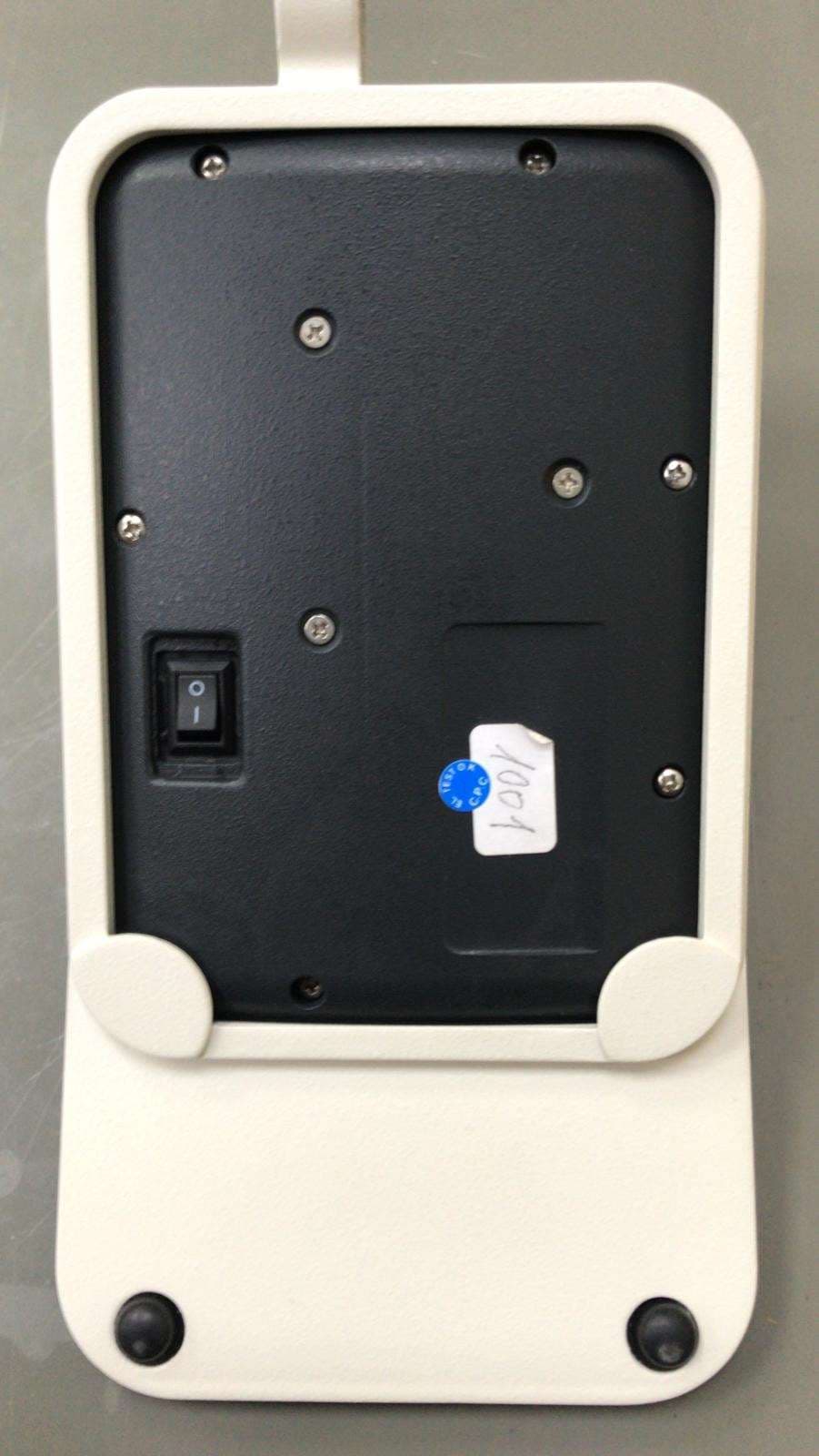
Click to zoom
Application Details
- Equipment Class
- DXT - Part 15 Low Power Transceiver, Rx Verified
- Date of Grant
- Apr 12, 2020
- Application Purpose
- Original Equipment
- Date of Application
- Apr 12, 2020
- Equipment Note
- 3D Control Device
- Frequency Range
- 2404.00000000 - 2477.00000000
- Company
- RealView Imaging Ltd.
- Country
- Israel
Documents & Files
Document Text
Text extracted from the exhibit documents filed with the FCC. Open a document above to read the original.
Users Manual
3D Control Device Operators Guide Live Interactive Holography System 3D Control Device Guide Copyright © 2020 RealView Imaging Ltd. All rights reserved. RealView Imaging Ltd. reserves the right to make changes to its products or specifications to improve performance, reliability, or manufacturability. Information furnished by RealView Imaging Ltd. is believed to be accurate and reliable. However, RealView Imaging Ltd. assumes no responsibility for its use. No license is granted by its implication or otherwise under any patent or patent rights of RealView Imaging Ltd. No part of this document may be produced or transmitted in any form or by any means, electronic or mechanical, for any purpose, without the express prior written permission of RealView Imaging Ltd. RealView Imaging Ltd. has patents and pending patent applications, trademarks, copyrights, or other intellectual property rights covering subject matter in this document. The furnishing of this document does not give you any license to these patents, trademarks, copyrights, or other intellectual property rights except as expressly provided in any written agreement from RealView Imaging Ltd. Manual Catalog Part Number: 20-18-003, Revision A Revision Date: March 2020 Contact information for equipment manufacturer and technical services: Manufacturer: RealView Imaging Ltd. Address: Hatnufa 4 Yokneam Israel 2069202 Tel: + 972-72-220-0177 Fax: + 972-72-220-0178 www.realviewimaging.com 1 Live Interactive Holography System 3D Control Device Guide 1. Product Overview Note For complete instructions pertaining to the HOLOSCOPE-i system’s deployment and operation, refer to the HOLOSCOPE-i system’s operation guide (P/N # 20-18-001). The 3D Control Device is used to navigate through functions that control hologram interaction. It is one of several ways of communicating with the HOLOSCOPE-i system and entering commands and provides the interface for performing interactions with the hologram. It is equipped with a complete set of hologram-manipulation buttons that duplicate the commands available on the touch-screen monitor and in the hologram itself. The 3D Control Device can be mounted on the bedside with the ability to easily remove it. The 3D Control Device is powered by an internal Lithium Ion (Li-On) battery. The battery should be recharged at least once a week. The 3D Control Device communicates with a USB Dongle that is located in the main system (This Dongle is FCCID: 2AAHQ-SMPW-RC). Isometric View Top View Figure 1: HOLOSCOPE-i System 3D Control Device 2 Live Interactive Holography System 3D Control Device Guide 2. Specifications Environmental Specifications ● Operational Environment: Ambient temperature: +10 to +30°C / +50 to +86°F Relative humidity: 30-80% (non-condensing) ● Transportation Environment (packaged): Ambient temperature: +10 to +30°C / +50 to +86°F Relative humidity: 30-80% (non-condensing) Protection Against Ingress of Liquids • 3D Control Device: IP20 3 Live Interactive Holography System 3D Control Device Guide 3. 3D Control Device Description The 3D Control Device incorporates buttons and a joystick that duplicate buttons seen on the HOLOSCOPE-i system’s main screen during the active session. The numbers of the following paragraphs correlate to the numbered arrows in Figure 2. Warning The 3D Control Device is powered by a rechargeable Li-Ion battery. Always ensure that the 3D Control Device is charged outside of the interventional suite. 1. Operational LED – indicates that the battery is charged, and the unit is ready to operate when properly paired with the system. 2. Menu – press this button to access the HOLOSCOPE-i system’s Holo-Menu. Available options are: Log off, Demo mode, Preferences and Settings, Software versions and Shut down. 3. 3-Dimensional Joystick – allows the operator to manipulate the hologram after the mode or action (Rotate, Zoom, etc.) has been activated. 4. Select – press this button to select a mark or a measurement that you made on the hologram (see # 5 and # 6 below). 5. Mark – activate this function to mark any anatomical landmark. A marker will appear on the screen. Use your finger or control device to mark the area in the visual field and press the Select button (see # 4 in Figure 2) to mark. 6. Measure – two measurements may be taken and saved on the hologram; press the Measure button to enter the appropriate mode. Measurements are made by marking two points in the hologram between which the measurement is desired, and then pressing the Select button (see # 4 in Figure 2). The anchor points of both measurements will be color-coded, and their length will be displayed on the screen. 7. Undo – press this button to reverse your last action. 8. Play – press this button to continue the stream during a real-time session. 9. Reset – all the hologram interactions (Rotate, Spin, Zoom, etc.) may be “un-done” in one move by pressing this button; the hologram will return to its original state as when loaded, and all marks will be removed. 10. Move – when this button is pressed, the hologram may be panned anywhere within the visual FOV. This is performed via the joystick (forward, backward, right, left, up or down). 4 Live Interactive Holography System 3D Control Device Guide Figure 2: 3D Control Device Description 11. Holo-capture – press this button to generate a static image at any time during the stream of the hologram; these images (captures) will be saved in the Saved Captures pop-up on the screen with a camera icon next to it. 12. Play Loop – press this button to play and replay the streaming data video in an endless loop; press it again to cease playing. 13. Brightness – press this button to define the brightness of the hologram. 14. Threshold – this mode defines how much data you are seeing in the hologram, allowing you the option of removing background electronic noise from the hologram’s image. Activate this function to display the scroll bar you may use to adjust the threshold. 5 Li…
Text truncated - open the document above for the full version.
Cover Letter(s)
Ma rch 23, 2020 Telefication B.V. Attn: Dept. FCC TCB Edisonstraat 12A 6902 PK ZEVENAAR The Netherlands Subject: Application for certification of a 3D Control Device, HOLOSCOPE-i, FCC ID: 2AVYSRV3D001 Dear Sir/Madam, Please find attached our application for certification of a 3D Control Device, brand name HOLOSCOPE-i , FCC ID: 2AVYSRV3D001, prepared in accordance with FCC Rules, parts 15, section 15.249. The product testing and this application for certification were performed by Hermon Laboratories, which is recognized and accredited by FCC, Test Firm Registration Number is 927748, Designation Number is I L1001. Hermon Labs responsible person is Mr. Michael Nikishin tel: +972 4626 8440 fax:+972 4628 8277 e- m ail: [email protected]. P lease send an invoice to Hermon Labs. We hope this application satisfies your requirements Sincerely yours, Y ehudit Kraizer VP Quality and Regulatory
Cover Letter(s)
RF_160, Issue 04 Declaration of Authorization We Name: RealView Imaging Ltd........................... Address: 4 Hatnufa Street ......... ............ ......... ....... City: Yokneam Industrial Zone, 2069202............ ...... ............. Country: Israel ......... ......... ...... ............ ......... ......... ................ Declare that: Name Representative of agent: ............. (1) Agent Company name: Hermon Laboratories Ltd. ............. Address: Harakevet Industrial Zone .............. City: Binyamina 30500 .............. Country Israel ............. is authorized to apply for Certification of the following product(s): Product description: 3D Control Device ........................... ......... ....... Type designation: HOLOSCOPE-i ......... ............ ......... ......... ....... Trademark: NA............................ ............ ....... Validity/ expiry date March 23, 2021............................... on our behalf. Date: March 23, 2020............ ............ ..... City: Yokneam ................................ Name: Yehudit Kraizer ................................ (2) Function: VP Quality and Regulatory ............................... Signature: ........................... .... Notes: (1): Required for FCC application (2): For FCC it must be the Grantee Code “owner” or the authorized agent.
Cover Letter(s)
FCC, Request for non-disclosure Date: 16-Jul-10 RF_501, Issue 6 Page 1 of 1 Company Name: RealView Imaging Ltd. Address : 4 Hatnufa Street City: Yokneam Industrial Zone 2069202, Country: Israel T o: Telefication B.V., Dept. FCC TCB Edisonstraat 12A 6902 PK ZEVENAAR T he Netherlands S ubject: Request for confidentiality FCC ID: 2AVYSRV3D001 R eference number: ###### Dear FCC TCB, 1 . Long-Term Confidentiality P ursuant to 47 CFR Section 0.459(a) & (b), we hereby requests non-disclosure and confidential treatment of the following materials submitted in support of FCC certification application: Bill(s) of Material Block Diagrams Operational Description Schematic Diagrams Tune-up Procedure A bove materials contain secrets, proprietary and technical information, which would customarily be guarded from competitors under 47 CFR, section 0.457(d)(2). Disclosure or publication or any portion of this company confidential material to other parties could cause substantial competitive harm and provide unjustified benefits for competitors. 2 . Short-Term Confidentiality (STC ) P ursuant to Public Notice DA 04-1705 of the Commission’s policy, in order to comply with the marketing regulations in 47 CFR §2.803 and the importation rules in 47 CFR §2.1204, a pplicant hereby requests Short-Term Confidential treatment of the following materials (note 1): Internal Photos User’s Manual Test Set-up Photos External Photos Justification: Trade secret. Not to permit to competitors to view the device interiors and to improve their products P lanned Release Date STC: 180 days from grant date (notes 2, 3, 4, 5) D ate: March 24, 2020 Name and signature of applicant: Yehudit Kraizer Notes: 1) A document or type of document can only have ONE type of confidentiality! 2) Short-Term confidentiality is in principle for 45 days from date of grant; it can be extended max 3 times (total time 180 days max.)! 3) FCC must be informed when marketing begins earlier. 4) Release takes place automatically thus extension must be requested in time. Telefication does not remind you of this! 5) Request for extension or for release must be received by Telefication at least 7 days before date of actual marketing or befor e ex piration of the STC period
External Photos
12 © 2020 RealView Imaging Ltd. All rights reserved. Confidential and Proprietary External Pictures Top View (In holder)Bottom View (In holder) Label 13 © 2020 RealView Imaging Ltd. All rights reserved. Confidential and Proprietary External Pictures Rear View (In holder)Front View (In holder) 14 © 2020 RealView Imaging Ltd. All rights reserved. Confidential and Proprietary External Pictures Right View (In holder)Left View (In holder) 15 © 2020 RealView Imaging Ltd. All rights reserved. Confidential and Proprietary External Pictures Bottom ViewTop View Label 16 © 2020 RealView Imaging Ltd. All rights reserved. Confidential and Proprietary External Pictures Rear View Front View 17 © 2020 RealView Imaging Ltd. All rights reserved. Confidential and Proprietary External Pictures Right ViewLeft View
ID Label/Location Info
RealView Imaging Ltd. FCC ID: 2AVYS RV3D001 Page 1 of 1 Label The label shown below is affixed on the bottom of the device. The label material is PVC with a permanent adhesive. Label location Label with FCC ID: 2AVYSRV3D001 will be located here.
Internal Photos
RealView Imaging Ltd. FCC ID: 2AVYSRV3D001 Page 1 of 11 INTERNAL PHOTOGRAPHS This document contains10 photographs RealView Imaging Ltd. FCC ID: 2AVYSRV3D001 Page 2 of 11 Photograph No.1 3D controller internal view RealView Imaging Ltd. FCC ID: 2AVYSRV3D001 Page 3 of 11 Photograph No.2 3D controller internal view RealView Imaging Ltd. FCC ID: 2AVYSRV3D001 Page 4 of 11 Photograph No.3 3D controller internal view with main PCB removed RealView Imaging Ltd. FCC ID: 2AVYSRV3D001 Page 5 of 11 Photograph No.4 3D controller main PCB front view RealView Imaging Ltd. FCC ID: 2AVYSRV3D001 Page 6 of 11 Photograph No.5 3D controller main PCB second side view RealView Imaging Ltd. FCC ID: 2AVYSRV3D001 Page 7 of 11 Photograph No.6 3D controller RF part RealView Imaging Ltd. FCC ID: 2AVYSRV3D001 Page 8 of 11 Photograph No.7 3D controller RF part RealView Imaging Ltd. FCC ID: 2AVYSRV3D001 Page 9 of 11 Photograph No.8 3D controller RF PCB front view RealView Imaging Ltd. FCC ID: 2AVYSRV3D001 Page 10 of 11 Photograph No.9 3D controller RF PCB second side view RealView Imaging Ltd. FCC ID: 2AVYSRV3D001 Page 11 of 11 Photograph No.10 3D controller antenna
Test Report
Hermon Laboratories Ltd. P.O. Box 23, Binyamina 3055001, Israel Tel. +972 4628 8001 Fax. +972 4628 8277 E-mail: [email protected] Report ID: REARAD_FCC_IC.37521 Page 1 of 51 Date of Issue:29-March-20 ELECTRICAL TESTING 0839.01 TEST REPORT ACCORDING TO: FCC 47CFR part 15 subpart C §15.249 and subpart B; RSS-210 Issue 9:2016; RSS-Gen Issue 5:2018, ICES-003 Issue 6:2016 FOR: RealView Imaging Ltd. 3D Control Device Model: HOLOSCOPE ™ i FCC ID: 2AVYSRV3D001 IC: 24096-RV3D001 This report is in conformity with ISO/ IEC 17025. The "A2LA Accredited" symbol endorsement applies only to the tests and calibrations that are listed in the scope of Hermon Laboratories accreditation. The test results relate only to the items tested. This test report shall not be reproduced in any form except in full with the written approval of Hermon Laboratories Ltd. Report ID: REARAD_FCC_IC.37521 Date of Issue: 29-March-20 Page 2 of 51 Table of contents 1 Applicant information ..................................................................................................................................................... 3 2 Equipment under test attributes .................................................................................................................................... 3 3 Manufacturer information .............................................................................................................................................. 3 4 Test details .................................................................................................................................................................... 3 5 Tests summary .............................................................................................................................................................. 4 6 EUT description ............................................................................................................................................................. 5 6.1 General information ....................................................................................................................................................... 5 6.2 Operating frequencies ................................................................................................................................................... 5 6.3 Test configuration .......................................................................................................................................................... 5 6.4 Changes made in EUT .................................................................................................................................................. 5 6.5 Transmitter characteristics ............................................................................................................................................ 5 7 Transmitter tests according to 47CFR part 15 subpart C and RSS-210 requirements ........................................................ 6 7.1 Field strength of emissions ............................................................................................................................................ 6 7.2 Occupied bandwidth test ............................................................................................................................................. 29 7.3 Band edge emission .................................................................................................................................................... 33 7.4 Antenna requirements ................................................................................................................................................. 36 8 Unintentional emissions ................................................................................................................................................ 37 8.1 Radiated emission measurements .............................................................................................................................. 37 9 APPENDIX A Test equipment and ancillaries used for tests ....................................................................................... 41 10 APPENDIX B Test equipment correction factors ......................................................................................................... 42 11 APPENDIX C Measurement uncertainties .................................................................................................................. 48 12 APPENDIX D Test laboratory description ................................................................................................................... 49 13 APPENDIX E Specification references........................................................................................................................ 49 14 APPENDIX F Abbreviations and acronyms ................................................................................................................. 50 15 APPENDIX G Manufacturer’s declaration ................................................................................................................... 51 Report ID: REARAD_FCC_IC.37521 Date of Issue: 29-March-20 Page 3 of 51 1 Applicant information Client name: RealView Imaging Ltd. Address: Hatnufa 4, P.O. Box 83, Industrial Zone Yokneam, Israel, 2069202 Telephone: +972-72-2200176 E-mail: [email protected] Contact name: Mrs. Yehudit Kraizer 2 Equipment under test attributes Product name: 3D Control Device Product type: Transceiver Model: HOLOSCOPE ™ i Serial number: 100001 Part number: BUY000501 Hardware version: 01 Driver version: 10.5.6 Receipt date May 2018 3 Manufacturer information Manufacturer name: RealView Imaging Ltd. Address: Hatnufa 4, P.O. Box 83, Industrial Zone Yokneam, Israel, 2069202 Telephone: +972-72-2200176 E-Mail: [email protected] Contact name: Mrs. Yehudit Kraizer 4 Test details Project ID: 31023 Location: Hermon Laboratories Ltd. P.O. Box…
Text truncated - open the document above for the full version.
Test Setup Photos
RealView Imaging Ltd. FCC ID: 2AVYSRV3D001 Page 1 of 8 SETUP PHOTOGRAPHS This document contains 7 photographs RealView Imaging Ltd. FCC ID: 2AVYSRV3D001 Page 2 of 8 Photograph No.1 Setup for spurious emission field strength measurements in the anechoic chamber below 30 MHz RealView Imaging Ltd. FCC ID: 2AVYSRV3D001 Page 3 of 8 Photograph No.2 Setup for carrier field strength, spurious emission field strength measurements in the anechoic chamber in 30 – 1000 MHz range RealView Imaging Ltd. FCC ID: 2AVYSRV3D001 Page 4 of 8 Photograph No.3 Setup for spurious emission field strength measurements in the anechoic chamber, EUT close view RealView Imaging Ltd. FCC ID: 2AVYSRV3D001 Page 5 of 8 Photograph No.4 Setup for spurious emission field strength measurements in the anechoic chamber in 1-18 GHz RealView Imaging Ltd. FCC ID: 2AVYSRV3D001 Page 6 of 8 Photograph No.5 Setup for spurious emission field strength measurements in the anechoic chamber in 18 – 25 GHz RealView Imaging Ltd. FCC ID: 2AVYSRV3D001 Page 7 of 8 Photograph No.6 Setup for spurious emission field strength measurements in the anechoic chamber above 1 GHz RealView Imaging Ltd. FCC ID: 2AVYSRV3D001 Page 8 of 8 Photograph No.7 Setup for OBW measurements
Contact Information
Applicant
Yehudit Kraizer(VP QA/RA)
Technical Contact
Hermon Laboratories Ltd.Michael Nikishin
[email protected]97246268440
Harakevet Industrial zone, P.O.Box 23 · Binyamina, · Israel
Non-Technical Contact
RealView Imaging Ltd.Yuval Yoreh
[email protected]972722200177
Test Firm
Hermon Laboratories Ltd.George Shleimovich
Technical Specifications
| # | Rule Parts | Frequency Range | Power Output |
|---|---|---|---|
| 1 | 15C | 2.40 GHz - 2.48 GHz | - |