2AVYV-2554432-01Satellite for indoor localization
TRUMPF Werkzeugmaschinen GmbH & Co. KG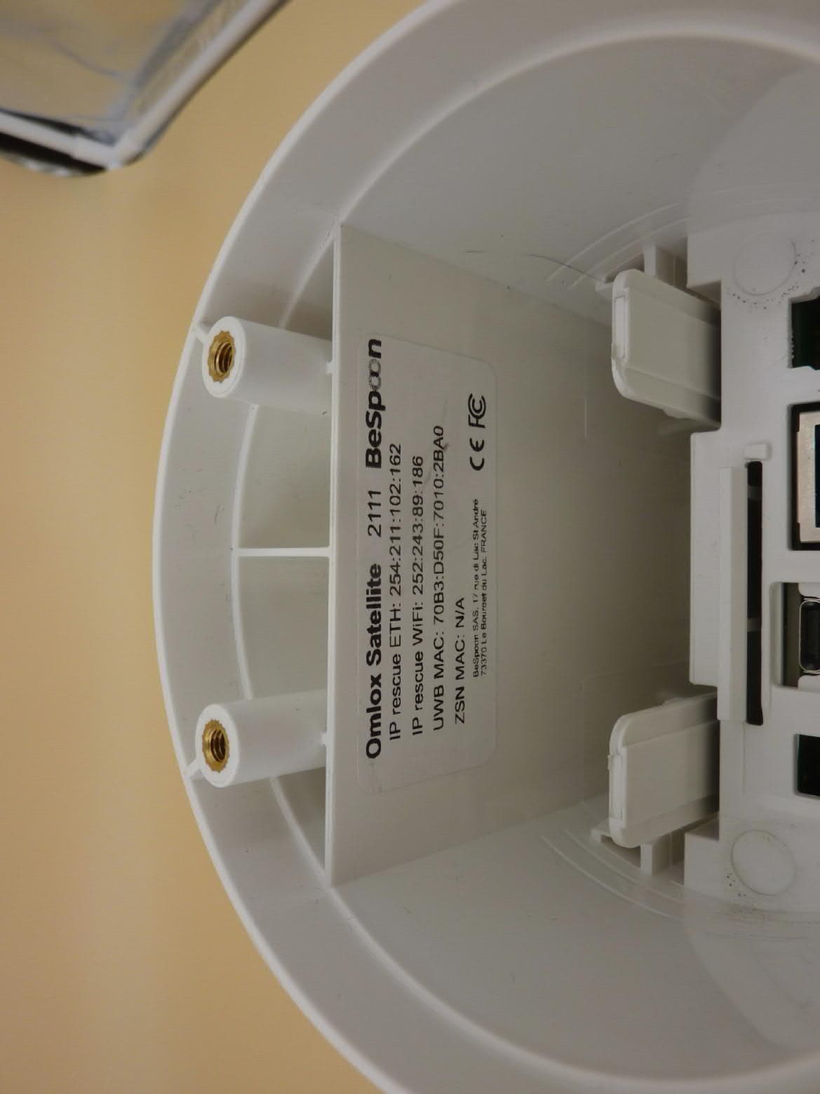
Click to zoom
Application Details
- Equipment Class
- UWB - Ultra Wideband Transmitter
- Date of Grant
- Mar 08, 2021
- Application Purpose
- Original Equipment
- Date of Application
- Mar 03, 2021
- Equipment Note
- Satellite for indoor localization
- Frequency Range
- 3575.00000000 - 4500.00000000
- Country
- Germany
Documents & Files
Document Text
Text extracted from the exhibit documents filed with the FCC. Open a document above to read the original.
Users Manual
Installation manual Track&Trace Edition 2020-06-01 TRUMPF Werkzeugmaschinen GmbH + Co. KG, Technische Redaktion Johann-Maus-Straße 2, D-71254 Ditzingen Fon: +49 7156 303 - 0 Internet: http://www.trumpf.com E-Mail: [email protected] Table of contents 1Components included2 2Customer checklist for installation prepa- ration 6 3Preparing the hall plan7 4Installation of the system8 4.1Mounting satellites8 4.2Start-up of preinstalled industrial PC10 C1105en2020-06-01 Table of contents 1 1.Components included There are different package sizes. The number of satellites and markers differs depending on the package size. Track&Trace componentsFig. 94174 1 TRUMPF logo (also used as a reference point during calibra- tion) 2 LED status ring SatelliteFig. 94260 2 Components included 2020-06-01C1105en Satellite 1 USB-C connection (power sup- ply) 2 Ethernet port (power supply and data transmission) Connecting the satelliteFig. 94278 1 LED status ring 2 E-Ink display 3 TRUMPF logo MarkerFig. 94175 The marker is charged by induction. C1105en 2020-06-01 Components included 3 Marker 1 Fastening clip Fastening set for markersFig. 98117 4 Components included 2020-06-01C1105en Fastening set for markers Charging station for markers 1 Connection to customer's net- work 2 Satellite network connection 3 Start-up of the service port 4 Power supply Preinstalled industrial PCFig. 96599 C1105en2020-06-01 Components included 5 Preinstalled industrial PC 2.Customer checklist for installation preparation No.DesignationNumberRemark 1Track&Trace components1Contents: satellites, operator's man- ual, markers, industrial PC, holders 2Current hall plan / layoutmin. 1Hall plan as background for the user interface (see "Preparing the hall plan", pg. 7) 3Fastening material (screws, dowels, cable ties, etc.) Depending on the position and type of mount- ing devices Assembly accessories for fixing the mounting devices including satellites 4Own assembly tools -Drill for dowels and screws 5Conductormin. 1Ladder should be tall enough to allow the satellites to be mounted safely 6Boom lift 1A boom lift or "cherry picker" must be used depending on the ceiling height 6.1Operator for boom lift1An authorized operator is required to operate the boom lift 7Network cable Depending on the area of the hall or the sec- tion Power supply of the satellites via PoE (Power over Ethernet) 8Patch cable1Data connection between industrial PC and your computer or main satel- lite 9PoE capable switch (does not need to be managed) Depending on network routing (min. number of satellites plus 1 port) Power supply and data connection of the satellites 10Device / laptop / desktop PC1Required for setting up the user interface (browser: Google Chrome, Mozilla Firefox, Windows Edge or Apple Safari) Check listTab. 1 6 Customer checklist for installation preparation 2020-06-01C1105en 3.Preparing the hall plan An up-to-date and suitable hall plan must be available at the commissioning date. A walk-through inspection of the hall is necessary in order to take into consideration the on-site conditions. The hall plan used also serves as a basic map for the localiza- tion in the user interface, and must meet certain requirements. Errors in the plan can lead to deviations in the marker position in the user interface. ■ The hall plan must be up-to-date; high bay storage racks, machines and other obstructions must be marked. ■ The hall plan must be exact, true to scale and dimensioned; the dimensions must refer to one zero point (ideally in the top left corner). Example: Hall plan Fig. 94274 C1105en2020-06-01 Preparing the hall plan 7 4.Installation of the system 4.1Mounting satellites The mounting position of the satellites is made available on a case-by-case basis by TRUMPF. The distance to cable bundles, cable racks and other electrical interference sources must be at least 1 m. Ideally directly on the wall, otherwise the distance to the wall must be < 5 cm or > 1 m. Interference (echo) occurs depending on the distance to the wall. The satellite must be located either very close to the wall or (e.g. when mounted on a ceiling) at a distance of at least 1 m from the wall. Note Use brackets supplied by TRUMPF! Tab. 2 There are three methods for fastening the satellite. ■ Holder (fastened in drilled holes in the wall) ■ Magnet with arrester loop ■ Mounting by clamping Notes ■ Do-it-yourself holders must not enclose or shield the satel- lite, so that the signal is not interfered with. ■ The TRUMPF logo must always point toward the tracking area. Means, Tools, Materials ■ Brackets for wall, ceiling or free-standing assembly. Drawing data can be found at: 8 Installation of the system 2020-06-01C1105en Instructions for assembly Fastening methods https://www.trumpf.com/en_US/products/software/software- products/tracktrace/ ■ Suitable screws and dowels ■ Hammer drill or standard drill ■ Safe ladder or boom lift 1 Drilled holes ExampleFig. 94277 1. Fasten holders to drilled holes in the wall, and fasten the sat- ellite in the holder. 2.Or Fasten the satellite with a magnet. Then an arrester loop must be attached. For safety reasons, however, it is recommended for a perma- nent fastening with screws to be used. 3.Or Clamp the satellite. C1105en 2020-06-01 Installation of the system 9 Fasten satellite 1 USB-C connection (power sup- ply) 2 Ethernet port (power supply and data transmission) Connecting the satelliteFig. 94278 4. Connect satellite via POE (RJ45) to the power supply and the network with the preinstalled industrial PC. An amplifier must be used if the cable is 100 m long or more. The light ring of the satellite must respond. or Ø In exceptional cases after consultation with TRUMPF: Connect satellite via USB-C with the power supply. The satellite is automatically switched on as soon as it is connected to the mains. 4.2Start-up of preinstalled industrial PC Conditions ■ One of the following browsers is available: Google Chrome, Mozilla Firefox, Windows Edge, Apple Safari…
Text truncated - open the document above for the full version.
Users Manual
Operator's manual Track&Trace Operator's manual Track&Trace Original operator's manual Edition 2020-10-01 Order Information Please specify when ordering this document: Operator's manual Track&Trace Edition 2020-10-01 Document number B1105en Address for orders TRUMPF GmbH + Co. KG Technische Redaktion Johann-Maus-Straße 2 D-71254 Ditzingen Fon: +49 7156 303 - 0 Internet: http://www.trumpf.com E-Mail: [email protected] © TRUMPF GmbH + Co. KG Table of contents 1Safety2 1.1Overview of residual risks2 FCC - safety and compliance 2 1.2Intended use4 1.3Frequencies and transmitting power4 1.4Climatic requirements5 1.5Disassembly and disposal5 1.6Data management5 2Technical Data7 3Operation9 3.1Settings9 Start screen with dashboard10 User management10 3.2Meaning of the LED lamps10 3.3Live view of markers and orders11 Filtering the markers11 Displaying the marker details12 3.4Switching on and resetting the marker12 3.5Connecting a marker with an order12 3.6Charging a marker13 3.7Diagnostics14 3.8Accessories and software14 4Spare parts list15 B1105en2020-10-01 Table of contents 1 1.Safety 1.1Overview of residual risks Residual riskHazard areaType of dangerMeasure to be taken by the user Mechanical hazard Bruises or knocks due to falling satellites SatelliteRisk of injuryCordon off the work area below the assembly area. Use the enclosed brackets or own-construction brackets according to the Operator's manual. Use the screw locks. Bruises, knocks due to falling charging station Charging stationSecure the charging station to the wall or table using screws/ bolts. Slipping, stumbling, falling over charging station placed in path Charging stationSecure the charging station to the wall or table using screws/ bolts. Bruises or knocks due to a fall- ing industrial PC Industrial PCSecure industrial PC to wall or table using screws/bolts. Slipping, stumbling, falling over industrial PC placed in path Industrial PCSecure industrial PC to wall or table using screws/bolts. Falling from lifting device/ladderLifting device/ladderUse suitable lifting devices and ladders. These should be assembled by qualified personnel only. Cuts due to edge of satellite retaining bracket Sharp edge of retaining bracket During assembly, wear gloves. Residual risksTab. 1 FCC - safety and compliance This device complies with Part 15 of the Federal Communica- tions Commission (FCC) Rules. Operation is subject to the fol- lowing two conditions: (1) this device may not cause harmful interference, and (2) this device must accept any interference received, including interference that may cause undesired opera- tion. This equipment has been tested and found to comply with the limits for a Class B digital device, pursuant to Part 15 of the FCC Rules. These limits are designed to provide reasonable pro- tection against harmful interference in a residential installation. This equipment generates, uses and can radiate radio frequency energy and, if not installed and used in accordance with the instructions, may cause harmful interference to radio communica- tions. However, there is no guarantee that interference will not occur in a particular installation. 2 Safety 2020-10-01B1105en If this equipment does cause harmful interference to radio or tel- evision reception, which can be determined by turning the equip- ment off and on, the user is encouraged to try to correct the interference by one of the following measures: ■ Reorient or relocate the receiving antenna, ■ Increase the separation between the equipment and receiver, ■ Connect the equipment into an outlet on a circuit different from that to which the receiver is connected, ■ Consult the dealer or an experienced radio/TV technician for help. This equipment may only be operated indoors. Ø Operation outdoors is in violation of 47 U.S.C. 301 and could subject the operator to serious legal penalties. This equipment may only be operated as a fixed instal- lation. Ø Mobile operation is in violation of 47 U.S.C. 301 and could subject the operator to serious legal penalties. UWB devices may not be employed for the operation of toys. Ø Operation onboard an aircraft, a ship or a satellite is prohib- ited. Changes or modifications Ø Any changes or modifications not expressly approved by TRUMPF could void the user's authority to operate this equipment. The Satellites only operate (i.e. receive and transmit UWB sig- nals) within a complete UWB real-time location system TRUMPF RTLS, which must be professionally installed. The installed sys- tem is configured to cover only the area inside the building, pre- venting the Satellites and other UWB devices of the system from emitting UWB signals outdoors. Contact your system admin- istrator if you are unsure as to the extent of coverage. . The local representative in terms of the Federal Communica- tions Commission (FCC) for the USA is: Anupam Chakraborty TRUMPF Inc.,1900 W Central Road, 60192 Hoffman Estates, USA Phone +775 (842) 3420 B1105en 2020-10-01 Safety 3 CAUTION CAUTION CAUTION CAUTION 1.2Intended use The system is designed for localization during sheet metal proc- essing. The user is allowed to monitor the location of production orders, load carriers, vehicles and tools with the system. Installation, operating and transport conditions defined by TRUMPF must be adhered to and maintenance work must be carried out in accordance with the Operator's manual. The user must observe the specifications of the country in which the machine is being operated as well as national and regional safety and accident prevention regulations. The following is not permitted: ■ Unauthorized alteration or conversion of the system by the user or personnel. ■ Any working procedure that impairs the safety. Persons carrying markers might be monitored. Processing of personal data. Ø People must not be given markers. Ø This creates personal data which, according to the Euro- pean General Data Protection Regulation, can only be proc- essed under defined requirements. Ø Obs…
Text truncated - open the document above for the full version.
Users Manual
User Guide OMLOX SATELLITE © 2020 TRUMPF The copyrights in this user guide and the system described therein are owned by the company TRUMPF Werkzeugmaschinen GmbH + Co. KG (hereafter also referred as " TRUMPF "). TRUMPF, the TRUMPF logo, omlox and the omlox logo are registered trademarks. All other brand names, product names, or trademarks belong to their respective holders. TRUMPF Werkzeugmaschinen GmbH + Co. KG, Johann-Maus-Str.2; 71254 Ditzingen, Germany Contact information: see back cover. Proprietary Statement/Use This document contains proprietary information of TRUMPF which may not be used, reproduced, or disclosed to any other parties for any other purpose without the express, written permission of TRUMPF. This document has been made available as part of the license that has been granted to an authorized user of TRUMPF software. It is intended solely for the information and use of parties operating and maintaining the equipment described herein. Use of this documentation is subject to the terms and limitations of that license agreement. This document describes all functionality that can be licensed for this product. Not all functionality described in this document may be available to you depending on your license agreement. If you are not aware of the relevant terms of your license agreement, contact sales at TRUMPF. Product Improvements Continuous improvement of products is a policy of TRUMPF. All specifications and designs are subject to change without notice. Liability Disclaimer TRUMPF takes steps to ensure that its published documentation is correct; however, errors do occur. TRUMPF reserves the right to correct any such errors and disclaims liability resulting there from. Limitation of Liability In no event shall TRUMPF, any of its licensors or anyone else involved in the creation, production, or delivery of the accompanying product (including hardware and software) be liable for any of the following (collectively referred to as "Injuries"): injuries (including death) or damages to persons or to property, or damages of any other kind, direct, indirect, special, exemplary, incidental or con- sequential, including, but not limited to, loss of use, lost profits, lost revenues, loss of data, business interruption, replacement costs, debt service or rental payments, or damages owing by you to others, whether arising out of contract, tort, strict liability or otherwise, arising from or relating to the design, use (or inability to use) or operation of these materials, the software, documentation, hardware, or from any services provided by TRUMPF (whether or not TRUMPF or its licensors knew or should have known of the possibility of any such Injuries) even if a remedy set forth herein is found to have failed of its essential purpose. Some jurisdictions do not allow the exclusion or limitation of incidental or consequential damages, so the above limitation or exclusion may not apply to you. Table of contents 1. Introduction 1 2. Safety and compliance information 2 3. Specification 4 3.1. Datasheet 4 3.2. Hardware overview 5 3.3. Antenna radiation patterns 7 3.4. Equipment needs 8 4. System configurations 9 4.1. IP assignment for omlox Satellites 9 4.2. omlox Satellite used as Wi-Fi access point 9 5. Deployment instructions 10 5.1. omlox Satellite start 10 5.2. omlox Satellite placement 10 5.3. omlox Satellite control 10 6. Ask for support 11 1 omlox Satellite User Guide x, y, z server-centric device-centric 1. Introduction omlox Satellite is part of TRUMPF RTLS, a real-time locating system which uses Ultra-Wideband (UWB) pulses for real-time 3D location of objects in buildings in various industries. omlox Satellites are used as fixed bases in TRUMPF RTLS. They are synchronized with each other and interface with mobile devices such as WTags and SmartAntennas. The mobile devices are tracked in two modes which can coexist: Multi- Tag Tracking (server-centric) and GPS-like Positioning (device-centric). TRUMPF RTLS overview This document includes regulatory information, as well as a detailed hardware specification and a description of its features. For detailed features and user instructions regarding the complete system, please refer to the TRUMPF RTLS documentation included in the RTLS DELIVERY Pack. The RTLS DELIVERY Pack includes documentation and the related software toolchain, to make the development processes easier. It contents evolves according to TRUMPF RTLS developments. 2 omlox Satellite User Guide 2. Safety and compliance information This device complies with Part 15 of the FCC Rules. Operation is subject to the following two conditions: (1) this device may not cause harmful interference, and (2) this device must accept any interference received, including interference that may cause undesired operation. This equipment has been tested and found to comply with the limits for a Class B digital device, pursuant to Part 15 of the FCC Rules. These limits are designed to provide reasonable protection against harmful interference in a residential installation. This equipment generates, uses and can radiate radio frequency energy and, if not installed and used in accordance with the instructions, may cause harmful interference to radio communications. However, there is no guarantee that interference will not occur in a particular installation. If this equipment does cause harmful interference to radio or television reception, which can be determined by turning the equipment off and on, the user is encouraged to try to correct the interference by one of the following measures: – Reorient or relocate the receiving antenna. – Increase the separation between the equipment and receiver. – Connect the equipment into an outlet on a circuit different from that to which the receiver is connected. – Consult the dealer or an experienced radio/TV technician for help. CAUTION: this equipment may only be operated indoors. Operation outdoors is in violation of 47 U.S.C. 301 and could subject the o…
Text truncated - open the document above for the full version.
Cover Letter(s)
Long/Short-term Confidentiality Request Federal Communications Commission Date: 03 March 2021 445 12 th SW, Washington D.C. USA FCC ID: 2AVYV-2554432-01 To Whom it may concerns, Pursuant to sections 0.457(d) and 0.459 of CFR 47 and to avoid premature release of sensitive information prior to marketing or release of the product to the public, we hereby request long-term confidential treatment of information accompanying this application as outlined below: ☒ Schematics ☒ Parts List ☒ Block Diagram ☐ Tune-Up Info ☒ Operational Description In addition, we hereby request the following exhibits contained in this application to be temporarily (short-term confidentiality) withheld from the public disclosure ☐ for an initial period of days ☐ until: ☒ not applicable ☐ External Photos ☐ Test Setup Photos ☐ Internal Photos ☐ Users Manual The above materials contain trade secrets and proprietary information not customarily released to the public. The public disclosure of these matters might be harmful to the applicant and provide unjustified benefits to its competitors. The applicant understands that pursuant to rule 0.457(d), disclosure of this application and all accompanying documentation will not be made before the date of the GRANT for this application. If you have any questions, please feel free to contact me. Yours sincerely, Sabrina Berghahn Authorized Agent
External Photos
External EUT photos Examiner: Thomas KÜHNRevision:00 Date of issue: 30.06.2020Order Number: 19-111161page 1 of 4 3-D-view 1 External EUT photos Examiner: Thomas KÜHNRevision:00 Date of issue: 30.06.2020Order Number: 19-111161page 2 of 4 3-D-view 2 External EUT photos Examiner: Thomas KÜHNRevision:00 Date of issue: 30.06.2020Order Number: 19-111161page 3 of 4 Connector view External EUT photos Examiner: Thomas KÜHNRevision:00 Date of issue: 30.06.2020Order Number: 19-111161page 4 of 4 Type plate view
ID Label/Location Info
Lable Location Info The lable located on the bottom inside casing and is accessible after removing dust cover manually without any tools
Internal Photos
Internal EUT photos Examiner: Thomas KÜHNRevision:00 Date of issue: 30.06.2020Order Number: 19-111161page 1 of 7 Internal view 1 (housing opened) Internal EUT photos Examiner: Thomas KÜHNRevision:00 Date of issue: 30.06.2020Order Number: 19-111161page 2 of 7 Internal view 2 (PCB removed) Internal EUT photos Examiner: Thomas KÜHNRevision:00 Date of issue: 30.06.2020Order Number: 19-111161page 3 of 7 PCB, top view Internal EUT photos Examiner: Thomas KÜHNRevision:00 Date of issue: 30.06.2020Order Number: 19-111161page 4 of 7 PCB, top view (shielding removed) Internal EUT photos Examiner: Thomas KÜHNRevision:00 Date of issue: 30.06.2020Order Number: 19-111161page 5 of 7 PCB, top view (shielding removed) With module information WLAN module with PCB antenna IEEE 802.15.4 Ant 0 & Ant1 UWB With PCB antenna BLE chip with PCB antenna Internal EUT photos Examiner: Thomas KÜHNRevision:00 Date of issue: 30.06.2020Order Number: 19-111161page 6 of 7 PCB, bottom view Internal EUT photos Examiner: Thomas KÜHNRevision:00 Date of issue: 30.06.2020Order Number: 19-111161page 7 of 7 PCB, bottom view (shielding removed)
Test Report
Königswinkel 10 32825 Blomberg, Germany Phone: +49 (0) 52 35 / 95 00-0 Fax:+49 (0) 52 35 / 95 00-10 [email protected] www.phoenix-testlab.de Test Report Report Number: F191161E6 Equipment under Test (EUT): omlox Satellite Applicant: TRUMPF Werkzeugmaschinen GmbH + Co. KG Manufacturer: TRUMPF Werkzeugmaschinen GmbH + Co. KG Examiner:Bernward ROHDEReport Number: F191161E6 Date of Issue: 04.08.2020Order Number: 19-111161Page 2 of 29 References [1] ANSI C63.10-2013, American National Standard of Procedures for Compliance Testing of Unlicensed Wireless Devices [2] FCC CFR 47 Part 15, Radio Frequency Devices Test Result The requirements of the tests performed as shown in the overview (clause 4) were fulfilled by the equipment under test. The complete test results are presented in the following. This test report is only valid in its original form. Any reproduction of its contents in extracts without written permission of the accredited test laboratory PHOENIX TESTLAB GmbH is prohibited. The test results herein refer only to the tested sample. PHOENIX TESTLAB GmbH is not responsible for any generalisations or conclusions drawn from these test results concerning further samples. Any modification of the tested samples is prohibited and leads to the invalidity of this test report. Each page necessarily contains the PHOENIX TESTLAB Logo and the TEST REPORT NUMBER. Tested and written by:Bernward ROHDE07.09.2020 Name Signature Date Reviewed and approved by:Bernd STEINER07.09.2020 Name Signature Date Examiner:Bernward ROHDEReport Number: F191161E6 Date of Issue: 04.08.2020Order Number: 19-111161Page 3 of 29 Contents:Page 1.1Applicant ....................................................................................................................................................... 4 1.2Manufacturer ................................................................................................................................................. 4 1.3Test Laboratory ............................................................................................................................................. 4 1.4EUT (Equipment under Test) ........................................................................................................................ 5 1.5Technical Data of Equipment ........................................................................................................................ 6 1.5.1802.11 WLAN mode .............................................................................................................................. 7 1.5.2802.15.4 Radio mode ............................................................................................................................ 9 1.5.3BLE Radio mode ................................................................................................................................. 10 1.5.4UWB Radio mode ............................................................................................................................... 11 1.5.5Ancillary Equipment / Equipment used for testing .............................................................................. 12 1.6Dates ........................................................................................................................................................... 12 2.1Description of function of the EUT .............................................................................................................. 13 2.2The following states were defined as the operating conditions .................................................................. 13 2.2.1Radio test ............................................................................................................................................ 13 2.2.2Operation mode 1 ............................................................................................................................... 13 5.1Maximum unwanted emissions ................................................................................................................... 16 5.1.1Method of measurement (radiated) ..................................................................................................... 16 5.1.2Test results (radiated) ......................................................................................................................... 22 5.1.2.1Test results (9 kHz – 30 MHz) ..................................................................................................... 22 5.1.2.2Test results (30 MHz – 1 GHz) .................................................................................................... 23 5.1.2.3Test results (above 1 GHz) ......................................................................................................... 24 Examiner:Bernward ROHDEReport Number: F191161E6 Date of Issue: 04.08.2020Order Number: 19-111161Page 4 of 29 Identification 1.1 Applicant Name:TRUMPF Werkzeugmaschinen GmbH + Co. KG Address:Johann-Maus-Str. 2, 71254 Ditzingen Country:Germany Name for contact purposes:Mr. Guido Schönhardt Phone:07156-303-36117 Fax:- eMail Address:[email protected] Applicant represented during the test by the following person: - 1.2 Manufacturer Name:TRUMPF Werkzeugmaschinen GmbH + Co. KG Address:Johann-Maus-Str. 2, 71254 Ditzingen Country:Germany Name for contact purposes:Mr. Guido Schönhardt Phone:07156-303-36117 Fax:- eMail Address:[email protected] Applicant represented during the test by the following person: - 1.3 Test Laboratory The tests were carried out by:PHOENIX TESTLAB GmbH Königswinkel 10 32825 Blomberg Germany Accredited by Deutsche Akkreditierungsstelle GmbH (DAkkS) in compliance with DIN EN ISO/IEC 17025 under Reg. No. D-PL-17186-01-05 and D-PL-17186-01-06, FCC Test Firm Accreditation designation number DE0004, FCC Test Firm Registration Number 469623, CAB Identifier DE0003 and ISED# 3469A. Examiner:Bernward ROHDEReport Number: F191161E6…
Text truncated - open the document above for the full version.
Test Report
Königswinkel 10 32825 Blomberg, Germany Phone: +49 (0) 52 35 / 95 00-0 Fax:+49 (0) 52 35 / 95 00-10 [email protected] www.phoenix-testlab.de Test Report Report Number: F191161E2 Equipment under Test (EUT): omlox Satellite Applicant: TRUMPF Werkzeugmaschinen GmbH + Co. KG Manufacturer: TRUMPF Werkzeugmaschinen GmbH + Co. KG Test engineer: Thomas KÜHNReport Number:F191161E2 Date of issue: 30.06.2020Order Number:19-111161page 2 of 43 References [1] ANSI C63.10-2013, American National Standard of Procedures for Compliance Testing of Unlicensed Wireless Devices [2] FCC CFR 47 Part 15, Radio Frequency Devices [3] 393764 D01 UWB FAQ v02,ULTRA-WIDEBAND (UWB) DEVICES FREQUENTLY ASKED QUESTIONS TEST RESULT The requirements of the tests performed as shown in the overview (clause 4) were fulfilled by the equipment under test. The complete test results are presented in the following. This test report is only valid in its original form. Any reproduction of its contents in extracts without written permission of the accredited test laboratory PHOENIX TESTLAB GmbH is prohibited. The test results herein refer only to the tested sample. PHOENIX TESTLAB GmbH is not responsible for any generalisations or conclusions drawn from these test results concerning further samples. Any modification of the tested samples is prohibited and leads to the invalidity of this test report. Each page necessarily contains the PHOENIX TESTLAB Logo and the TEST REPORT NUMBER. Tested and written by: Thomas KÜHN30.06.2020 NameSignatureDate Reviewed and approved by: Bernd STEINER30.06.2020 Name Signature Date Test engineer: Thomas KÜHNReport Number:F191161E2 Date of issue: 30.06.2020Order Number:19-111161page 3 of 43 Contents:Page 1Identification ............................................................................................................................................. 4 1.1Applicant ........................................................................................................................................... 4 1.2Manufacturer .................................................................................................................................... 4 1.3Test laboratory ................................................................................................................................. 4 1.4EUT (Equipment Under Test)........................................................................................................... 5 1.5Technical data of equipment ............................................................................................................ 5 1.6Dates ................................................................................................................................................ 5 2Operational states .......................................................................…
Text truncated - open the document above for the full version.
Contact Information
Applicant
Sebastian Ochs(RD TruConnect Methods Tools MT)
Test Firm
PHOENIX TESTLAB GmbHHolger Bentje
Technical Specifications
| # | Rule Parts | Frequency Range | Power Output |
|---|---|---|---|
| 1 | 15F | 3.58 GHz - 4.50 GHz | - |