2AVZD-MND3018775ACTIVE WEATHERIZED OUTDOOR SPEAKERS
Zhejiang Focus-On Import & Export Co.,Ltd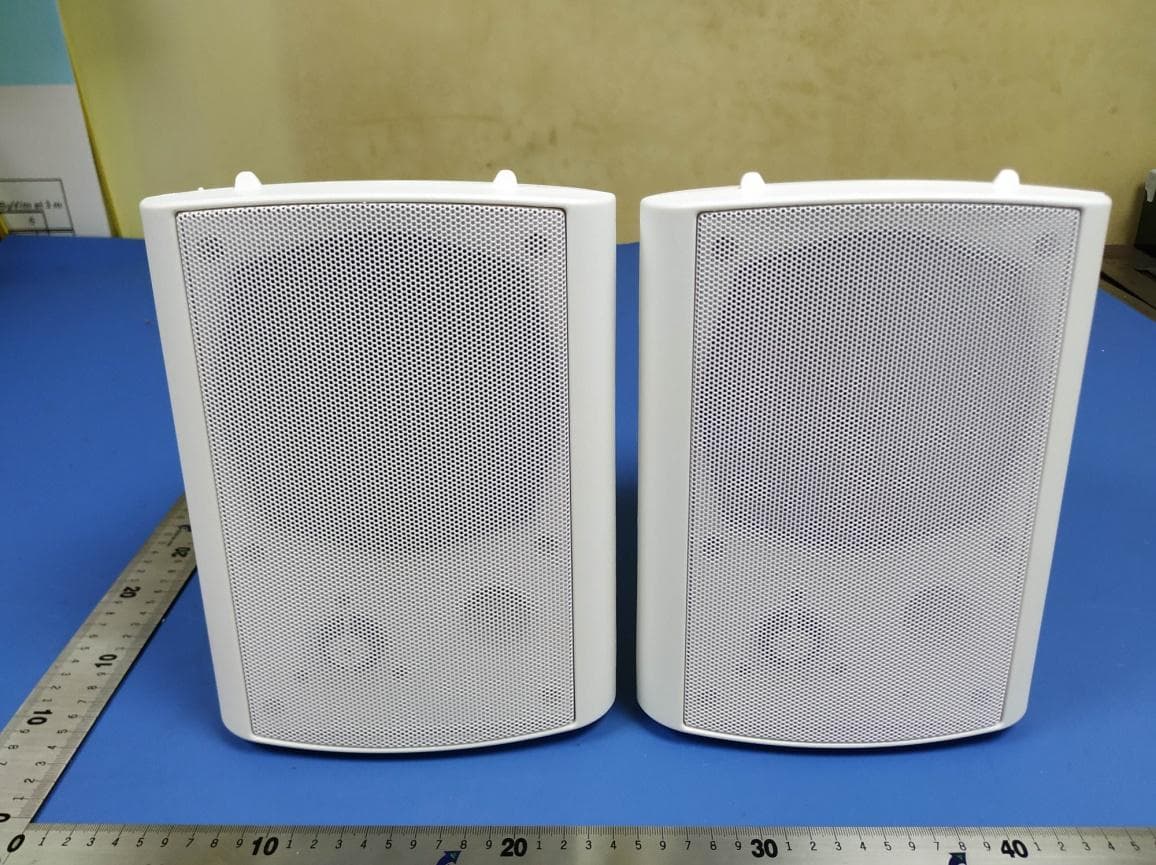
Click to zoom
Application Details
- Equipment Class
- DSS - Part 15 Spread Spectrum Transmitter
- Date of Grant
- Apr 08, 2020
- Application Purpose
- Original Equipment
- Date of Application
- Apr 08, 2020
- Equipment Note
- ACTIVE WEATHERIZED OUTDOOR SPEAKERS
- Frequency Range
- 2402.00000000 - 2480.00000000
- Country
- China
Documents & Files
Document Text
Text extracted from the exhibit documents filed with the FCC. Open a document above to read the original.
Users Manual
Read this material before using this product. Failure to do so can result in serious injury. SAVE THIS MANUAL. ACTIVE WEATHERIZED OUTDOOR SPEAKERS 301-8775 Instruction Manual Page 1 FCC NOTICE Specification Bluetooth Distance: Power Output Frequence Response Impedance Sensitivity Woofer Tweeter Product Dimension (1 Speaker) 39' 30W+30W RMS 80Hz - 20KHz 8Ω 89dB ± 3dB 5.25” 0.75” Silk Dome 9.6”H x 7.2”W x 7.2”D This device complies with part 15 of the FCC Rules. Operation is subject to the following two conditions: (1) This device may not cause harmful interference, and (2) this device must accept any interference received, including interference that may cause undesired operation. Package Contents Product Function Active Speaker Passive Speaker AC/DC Adapter16' Speaker Cable40" AUX-in Cable 1 2 3 4 1: LED INDICATOR 2: DC IN JACK (POWER) 3: ACTIVE SPEAKER OUTPUT 4: ON/OFF SWITCH 5: 3.5MM AUX-IN JACK FrontBack 5 Page 2 These outdoor speakers are manufactured to resist a variety of weather conditions. Snow, rain and sun (not to be submerged under water). For durability / longevity we do recommend removing the speakers from the brackets and placing inside during extended extreme temperatures over 120 degrees Fahrenheit and below 0 degrees Fahrenheit. The most ideal place to install these speakers is under the overhangs as they provide the best protection. Like all speakers, they sound the best when placed no more than eight feet apart from each other, and slightly higher than ear level. When choosing the speaker location - consider the location of the power source. The Active Speaker should be placed near the power source. The Passive Speaker could be placed further away and should be connected to the Active Speaker. Installation If your application requires the speaker to be mounted, please follow these directions. 1. Using the appropriate screws mount the bracket. (Fig.1) 2. Attach the speakers to the brackets using the large plastic knobs supplied.(Fig.2 & 3) Screw the bracket knobs into the cabinet. Point the speaker toward the listening area. Once the direction of the speaker has been determined tighten the bracket knobs securely. Knob 123 Connection 100-240V AC ON/OFF Knob Active SpeakerPassive Speaker Audio Device Page 3 When connecting the speakers, it is very important to observe the correct polarity. This means that the wire attached to the (+), red, or positive terminals on one component must be attached to the (+), red, or positive terminal on the corresponding component speaker output terminals. Similarly, the (-), Black, Negative or ground terminals must connect to the respective (-), Black, Negative, or ground terminals. This is easy to do by locating the color stripes that appears on the included speaker wire. If longer wire run is needed use 16 gauge weatherproof wire up to 50 feet. 1. Insert the weather proof connector from the supplied AC/DC Adaptor to the DC IN Jack on the Active Speaker. Insert the AC/DC adaptor to a wall outlet having AC 100-240V, 50/60Hz. 2. Push the POWER ON/OFF Switch on the rear of Active Speaker to ON position to turn the speaker to Standby mode. The LED Indicator on the Active Speaker will light. 3. Select input source A. If AUX is selected, please connect the Active Speaker to External Audio Device with supplied AUX-in cable into 3.5mm Jack. Then the speakers will play the music in the connected Audio Device. B. If Bluetooth is selected, please activate the Bluetooth of your device and pair the speakers as below. a. Turn on your Bluetooth Device, and open the Bluetooth function. b. Search Bluetooth Device: Ultra Performance. c. Select device “Ultra Performance” for automatic connection. d. There will be a notification sound and the LED indicator will turn to red once the pairing is successful. e. Play the music and control volume via the paired Bluetooth device Notes: When AUX is selected, please disconnect the Bluetooth device firstly, and the LED indicator should be green. Operations Connect Right and Left Channel Set (Red=Positive/Black=Negative) DO NOT RETURN TO STORE For Customer Service: Email: [email protected] Phone: 1-877-898-3958 This device complies with Part 15 of the FCC rules. Operation is subject to the following two conditions: 1) this device may not cause harmful interference, and 2) this device must accept any interference received, including interference that may cause undesired operation. C hanges or modifications not expressly approved by the party responsible for compliance could void your authority to operate the equipment. T his equipment has been tested and found to comply with the limits for a Class B digital device, pursuant to Part 15 of the FCC rules. These limits are designed to provide reasonable protection against harmful interference in a residential installation. This equipment generates, uses and can radiate radio frequency energy and if not installed and used in accordance with the instructions, may cause harmful interference to radio communications. However, there is no guarantee that interference will not occur in a particular installation. If this equipment does cause harmful interference to radio or television reception, which can be determined by turning the equipment off and on, the user is encouraged to try correct the interference by one or more of the following measures: -Reorient the receiving antenna. -I ncrease the separation between the equipment and receiver. -C onnect the equipment into and outlet on a circuit different from that to which the receiver is connected. -C onsult the dealer or an experienced radio/TV technician for help.
External Photos
Model No.: 301-8775
Internal Photos
Model No.: 301-8775
RF Exposure Info
RF Exposure evaluation According to 447498 D01 General RF Exposure Guidance v05 The 1-g and 10-g SAR test exclusion thresholds for 100 MHz to 6 GHz at test separation distances ≤ 50 mm are determined by: [(max. power of channel, including tune-up tolerance, mW)/(min. test separation distance, mm)] ·[√ f(GHz)] ≤ 3.0 for 1-g SAR and ≤ 7.5 for 10-g extremity SAR, where f(GHz) is the RF channel transmit frequency in GHz Power and distance are rounded to the nearest mW and mm before calculation The result is rounded to one decimal place for comparison Worse case is as below: [2441 MHz -2.15 dBm( 0.61 mW)output power] (0.61 mW /5mm) ·[√2.4 41(GHz)]= 0.2 <3.0 for 1-g SAR Then SAR evaluation is not required
Test Report
Report No. : BLA-EMC-202003-A24-01 1 Cover PageFCC Report (Bluetooth) Product Name : ACTIVE WEATHERIZED OUTDOOR SPEAKERS Trade mark : ULTRA PERFORMANCE, SONTAX, MAGNUM, Bridgeland, Ridgeline, Steel Core Model No. : 301-8775 FCC ID : 2AVZD-MND3018775 Report Number : BLA-EMC-202003-A24-01 Date of sample receipt : March 19, 2020 Date of Test : March 19, 2020–March 27, 2019 Date of Issue : March 30, 2020 Test standard : FCC CFR Title 47 Part 15 Subpart C Section 15.247 Test result : PASS Prepared for: Zhejiang Focus-On Import & Export Co., Ltd 40F Intime Centre, 1600 Kijiguan Street Binjiang, Hangzhou, Zhejiang, China Prepared by: BlueAsia of Technical Services(Shenzhen) Co., Ltd. IOT Test Centre of BlueAsia No. 448 Bulong Road, Bantian Street, Longgang District, Shenzhen, China TEL: +86-755-28682673 FAX: +86-755-28682673 Compiled by: Review by: Approved by: Date: March 30, 2020 Report No. : BLA-EMC-202003-A24-01 Page 2 of 50 BlueAsia of Technical Services(Shenzhen) Co., Ltd. IOT Test Centre of BlueAsia, No. 448 Bulong Road, Bantian Street, Longgang District, Shenzhen, China Telephone: TEL: +86-755-28682673 FAX: +86-755-28682673 2 Version Version No. Date Description 00 March 30, 2020 Original Report No. : BLA-EMC-202003-A24-01 Page 3 of 50 BlueAsia of Technical Services(Shenzhen) Co., Ltd. IOT Test Centre of BlueAsia, No. 448 Bulong Road, Bantian Street, Longgang District, Shenzhen, China Telephone: TEL: +86-755-28682673 FAX: +86-755-28682673 3 Contents Page 1 COVER PAGE ...........................................................................................................................................1 2 VERSION ...................................................................................................................................................2 3 CONTENTS ...............................................................................................................................................3 4 TEST SUMMARY ......................................................................................................................................4 5 GENERAL INFORMATION .......................................................................................................................5 5.1 GENERAL DESCRIPTION OF EUT ..........................................................................................................5 5.2 TEST MODE .........................................................................................................................................7 5.3 TEST FACILITY.....................................................................................................................................7 5.4 TEST LOCATION...................................................................................................................................7 5.5 OTHER INFORMATION REQUESTED BY THE CUSTOMER ..........................................................................7 5.6 DESCRIPTION OF SUPPORT UNITS ........................................................................................................7 6 TEST INSTRUMENTS LIST ......................................................................................................................8 7 TEST RESULTS AND MEASUREMENT DATA .....................................................................................10 7.1 ANTENNA REQUIREMENT ....................................................................................................................10 7.2 CONDUCTED EMISSIONS ....................................................................................................................11 7.3 CONDUCTED PEAK OUTPUT POWER ...................................................................................................14 7.4 20DB EMISSION BANDWIDTH ..............................................................................................................17 7.5 CARRIER FREQUENCIES SEPARATION .................................................................................................20 7.6 HOPPING CHANNEL NUMBER .............................................................................................................23 7.7 DWELL TIME ......................................................................................................................................24 7.8 PSEUDORANDOM FREQUENCY HOPPING SEQUENCE ...........................................................................26 7.9 BAND EDGE.......................................................................................................................................27 7.9.1 Conducted Emission Method ......................................................................................................27 7.9.2 Radiated Emission Method .........................................................................................................30 7.10 SPURIOUS EMISSION .........................................................................................................................32 7.10.1 Conducted Emission Method ..................................................................................................32 7.10.2 Radiated Emission Method .....................................................................................................34 8 TEST SETUP PHOTO .............................................................................................................................41 9 EUT CONSTRUCTIONAL DETAILS .......................................................................................................43 Report No. : BLA-EMC-202003-A24-01 Page 4 of 50 BlueAsia of Technical Services(Shenzhen) Co., Ltd. IOT Test Centre of BlueAsia, No. 448 Bulong Road, Bantian Street, Longgang District, Shenzhen, China Telephone: TEL: +86-755-28682673 FAX: +86-755-28682673 4 Test Summary Test Item Section in CFR 47 Result Antenna Requirement 15.203/15.247 (c) Pass AC Power Line Conducted Emission 15.207 Pass Cond…
Text truncated - open the document above for the full version.
Test Setup Photos
Model No.: 301-8775
Contact Information
Applicant
Lei Qin(Sourcing Manager)
Test Firm
BlueAsia of Technical Services (Shenzhen)Blue Zheng
[email protected]+86 755-23059481-815
Technical Specifications
| # | Rule Parts | Frequency Range | Power Output |
|---|---|---|---|
| 1 | 15C | 2.40 GHz - 2.48 GHz | 610.00 µW |