2AW5S-SC9127Counter 2
R-ZERO SYSTEMS, INC.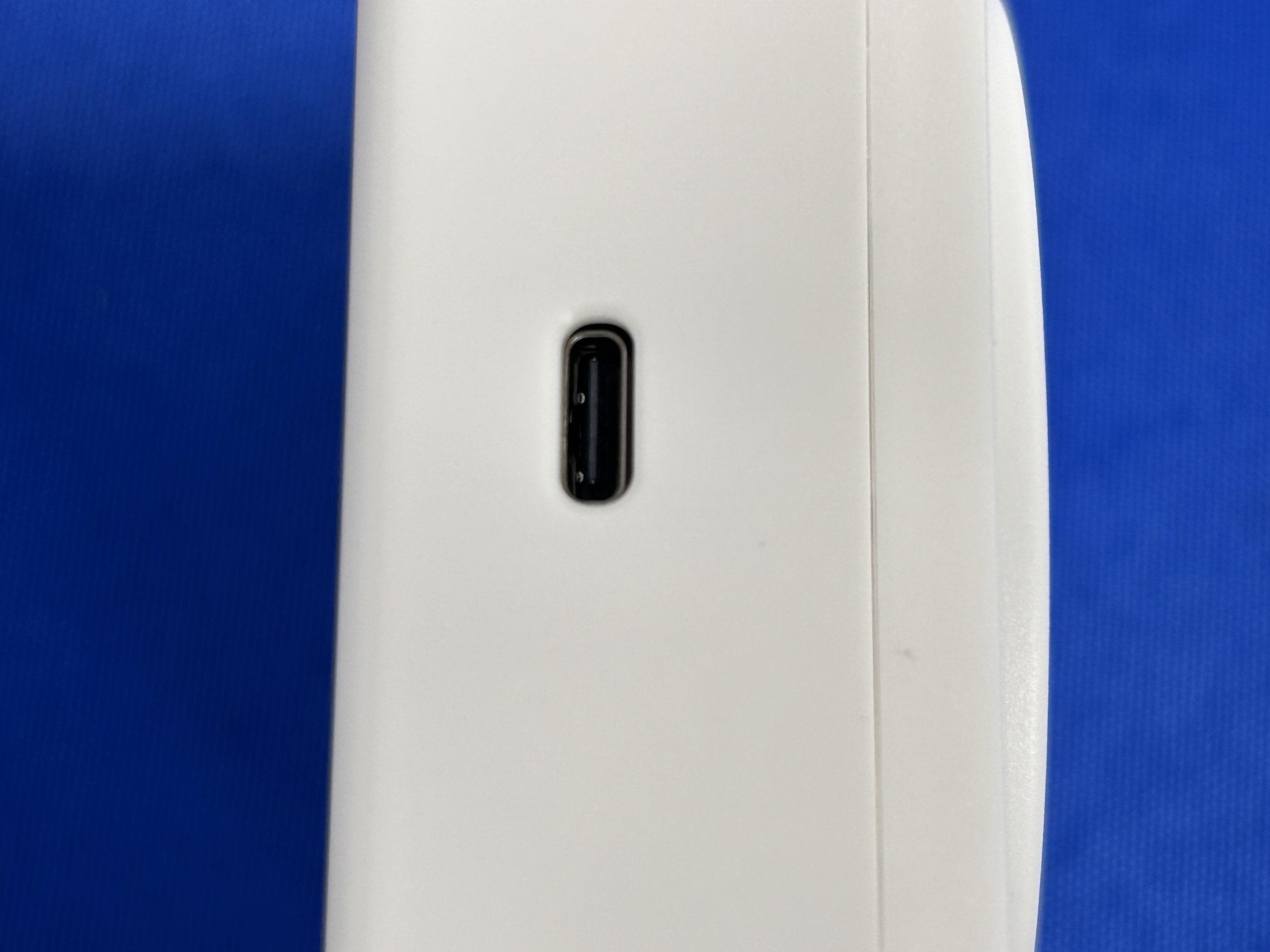
Click to zoom
Application Details
- Equipment Class
- DTS - Digital Transmission System
- Date of Grant
- Aug 28, 2024
- Application Purpose
- Original Equipment
- Date of Application
- Aug 28, 2024
- Equipment Note
- Counter 2
- Frequency Range
- 2402.00000000 - 2480.00000000
- Company
- R-ZERO SYSTEMS, INC.
- Country
- United States
Documents & Files
Document Text
Text extracted from the exhibit documents filed with the FCC. Open a document above to read the original.
Users Manual
©CoWorkr, an R-Zero Subsidiary: Counter V1 Documentation V1.0 R ZERO - Counter Sensor Manual 11 July 2023 2 PURPOSE // Information on how to use R ZERO’sCounter 2 Sensor DEFINITIONS // Counter 2 Sensor (a.k.a. “WorkSpace Counter 2”) R ZERO “WorkSpace Counters 2” are battery powered people counters that use a visible camera and AI for counting humans. Counters are ceiling mounted and may be used in a variety of applications wherein multiple occupants may be present. Counters may also be wired in positioned at thresholds for in/out counting. • Counters are “overhead sensors” that require being attached to the ceiling. • Counters include a specific mechanical attachment that mounts to the sensor location ceiling type. • Counters have an on/off switch but all sensors ship to installers with batteries installed and turned on. • Counters have a Label with an ID. DEVICE SETTINGS & CONFIGURATION // R ZERO Counters have several configurations that turn the device on/off, as well as control the data that they transmit. Otherwise, they simply carry out the instructions provided by the firmware. Above: Left: Front/Rear diagram of Counter components and switches. Right: Power Switch close-up 3 Powering On/Off: Counters have an on/off switch. To power on a Counter, flip the ON/OFF toggle switch to the ON position. To turn off, flip the switch to the OFF position. Switch Configurations: The AI-Confidence threshold can be set by configuring the switches in 4 positions. By setting the threshold to a specific setting, the object detections created by the firmware will be limited to the meet the criteria outlined in the diagram above. FIRMWARE AND FLASHING // R ZERO Counters ship pre-flashed with the latest firmware. For updates to the firmware, the device must be attached to an installer’s computer using a JTAG connector, wherein the firmware revision can be flashed onto the device. Firmware updates are not commonly done on production devices. Over the air update will be possible on the next generation firmware. INSTALLATION // Install Overview Similar to WorkPoints Sensors, our Counter Sensors have specific locations in which they are to be installed. Each device has an ID that must match the location found on the attached floor plans. Counter Sensors also require a specific position on a ceiling, centered over the work area and spaced a proper distance away from other sensors. 4 Use the (included) floor plans to locate each sensor. Sensors are typically ordered numerically so the installer should be able to make a continuous path through the floor plan while installing sensors in the order of the devices in the box. The following steps describe how to install the Counter Sensors based on the ceiling type. 5 Ceiling Type 1: Acoustic Ceiling Tile (ACT) Frame PART ONE Install the Counter Sensor using the drawings below and checklist below as guidelines for specific placement. ❏ Center the sensor on the space. The sensor location on the plan should indicate if the sensor is centered on the room or above a specific area of the room. ❏ Locate the Sensor on the nearest ACT Frame. This may be slightly off-center of the room. ❏ Use the included Frame clip to attach the Counter to the Frame as shown in the next slide. 6 PART TWO - OPTION 1 - Using a Clip Your Sensor should ship with a twist/clamp-on attachment to match your ACT System. Use the location determined using the guidelines on the previous sheet ❏ Attach using Frame Clip (image right): ❏ Squeeze the Clamp onto the T-Bar ❏ Twist the Counter onto the Stem ❏ Orient the Counter with the white lens at the top of the floor plan. Do Not Overtighten 7 PART TWO - OPTION 2 - Using a Magnet If your Sensor shipped with a magnet attachment. This can be used to attach to any surface with strong magnetic properties. Note: Magnets will not attach to aluminum frames. ❏ Use the location determined using the guidelines on the previous sheet 8 ❏ Attach using Magnets: ❏ Locate the position on the metal ACT frame or other metal surface that orients the Sensor with the white lens to the top of the floor plan ❏ Ceiling Type 2: Solid gypsum, metal, wood, etc. PART ONE The drawing below indicates the typical installation into a solid material ceiling. Depending on your specific ceiling type, there may be slight differences. Please ask if you have any questions prior to drilling or damaging any materials. ❏ Locate the mounting position using the drawings and ceiling type 9 ❏ Drill a ½” hole in the surface ❏ Insert the SnapToggle or other Threaded Anchor product included with your shipment ❏ Tighten the Threaded Anchor into place ❏ Gently Twist the Counter into the Anchor ❏ Orient the Sensor to position the white lens closest to the top of the floor plan and parallel to the space’s walls. Do not over tighten. ❏ Ceiling Type 2: Solid gypsum, metal, wood, etc. PART TWO Install the Counter Sensor using the drawings below and checklist below as guidelines for specific placement. 10 ❏ Center the sensor on the space. The sensor location on the plan should indicate if the sensor is centered on the room or above a specific area of the room. ❏ Locate the Sensor on the nearest ACT Frame. This may be slightly off-center of the room. ❏ Use the included Frame clip to attach the Counter to the Frame as shown in the next slide. ❏ T-Bar 11 FREQUENTLY ASKED QUESTIONS // A Counter Sensor is showing offline on our FloorPlan, what can I do? ● If it’s a single Counter Sensor amongst multiple other online Counter Sensors, it’s likely the battery. Remove the Counter Batteries and replace. Please note these takes 3.6V LI AA batteries, not conventional AA. If swapping the battery does not resolve the issue, please contact R ZERO and we’ll send you a replacement. ● If multiple Counter Sensors are offline: ● The sensors may be out of range of the nearest Hub, try moving a Hub closer to test the connection. Sometimes a sensor’s signal may be blocked depending on its installed location. Please reach out to R …
Text truncated - open the document above for the full version.
External Photos
Page1of4FCCID:2AW5S-SC9127 ShenzhenLCSComplianceTestingLaboratoryLtd. Add:101,201BldgA&301BldgC,JujiIndustrialParkYabianxueziwei,ShajingStreet,BaoanDistrict,Shenzhen, 518000,China Tel:+(86)0755-82591330|E-mail:[email protected]|Web:www.lcs-cert.com Scancodetocheckauthenticity ExternalPhotosoftheEUT Fig.1 Fig.2 Page2of4FCCID:2AW5S-SC9127 ShenzhenLCSComplianceTestingLaboratoryLtd. Add:101,201BldgA&301BldgC,JujiIndustrialParkYabianxueziwei,ShajingStreet,BaoanDistrict,Shenzhen, 518000,China Tel:+(86)0755-82591330|E-mail:[email protected]|Web:www.lcs-cert.com Scancodetocheckauthenticity Fig.3 Fig.4 Page3of4FCCID:2AW5S-SC9127 ShenzhenLCSComplianceTestingLaboratoryLtd. Add:101,201BldgA&301BldgC,JujiIndustrialParkYabianxueziwei,ShajingStreet,BaoanDistrict,Shenzhen, 518000,China Tel:+(86)0755-82591330|E-mail:[email protected]|Web:www.lcs-cert.com Scancodetocheckauthenticity Fig.5 Fig.6 Page4of4FCCID:2AW5S-SC9127 ShenzhenLCSComplianceTestingLaboratoryLtd. Add:101,201BldgA&301BldgC,JujiIndustrialParkYabianxueziwei,ShajingStreet,BaoanDistrict,Shenzhen, 518000,China Tel:+(86)0755-82591330|E-mail:[email protected]|Web:www.lcs-cert.com Scancodetocheckauthenticity Fig.7
ID Label/Location Info
Page 1 of 1 FCCID:2AW5S-SC9127IC:28838-SC9127 ShenzhenLCSComplianceTestingLaboratoryLtd. Add:101,201BldgA&301BldgC,JujiIndustrialParkYabianxueziwei,ShajingStreet,BaoanDistrict,Shenzhen, 518000,China Tel:+(86)0755-82591330|E-mail:[email protected]|Web:www.lcs-cert.com Scancodetocheckauthenticity LABELANDLOCATION LabelLocation
Internal Photos
Page1of5FCCID:2AW5S-SC9127 ShenzhenLCSComplianceTestingLaboratoryLtd. Add:101,201BldgA&301BldgC,JujiIndustrialParkYabianxueziwei,ShajingStreet,BaoanDistrict,Shenzhen, 518000,China Tel:+(86)0755-82591330|E-mail:[email protected]|Web:www.lcs-cert.com Scancodetocheckauthenticity InternalPhotosoftheEUT Fig.1 Fig.2 Page2of5FCCID:2AW5S-SC9127 ShenzhenLCSComplianceTestingLaboratoryLtd. Add:101,201BldgA&301BldgC,JujiIndustrialParkYabianxueziwei,ShajingStreet,BaoanDistrict,Shenzhen, 518000,China Tel:+(86)0755-82591330|E-mail:[email protected]|Web:www.lcs-cert.com Scancodetocheckauthenticity Fig.3 Fig.4 Page3of5FCCID:2AW5S-SC9127 ShenzhenLCSComplianceTestingLaboratoryLtd. Add:101,201BldgA&301BldgC,JujiIndustrialParkYabianxueziwei,ShajingStreet,BaoanDistrict,Shenzhen, 518000,China Tel:+(86)0755-82591330|E-mail:[email protected]|Web:www.lcs-cert.com Scancodetocheckauthenticity Fig.5 Fig.6 Page4of5FCCID:2AW5S-SC9127 ShenzhenLCSComplianceTestingLaboratoryLtd. Add:101,201BldgA&301BldgC,JujiIndustrialParkYabianxueziwei,ShajingStreet,BaoanDistrict,Shenzhen, 518000,China Tel:+(86)0755-82591330|E-mail:[email protected]|Web:www.lcs-cert.com Scancodetocheckauthenticity Fig.7 Fig.8 Antenna Page5of5FCCID:2AW5S-SC9127 ShenzhenLCSComplianceTestingLaboratoryLtd. Add:101,201BldgA&301BldgC,JujiIndustrialParkYabianxueziwei,ShajingStreet,BaoanDistrict,Shenzhen, 518000,China Tel:+(86)0755-82591330|E-mail:[email protected]|Web:www.lcs-cert.com Scancodetocheckauthenticity Fig.9
RF Exposure Info
Page1of3FCCID:2AW5S-SC9127 ShenzhenLCSComplianceTestingLaboratoryLtd. Add:101,201BldgA&301BldgC,JujiIndustrialParkYabianxueziwei,ShajingStreet,BaoanDistrict,Shenzhen, 518000,China Tel:+(86)0755-82591330|E-mail:[email protected]|Web:www.lcs-cert.com Scancodetocheckauthenticity FCCRFExposureEvaluation 1.ProductInformation Productname:Counter2 TestModel:SC9127 Ratings:Input:DC5V,24mA LS145003.6VLi-SOCL2Cell HardwareVersion:/ SoftwareVersion:/ BluetoothFrequencyRange:2402MHz~2480MHz ChannelNumber:40channelsforBluetoothV4.2(DTS) ChannelSpacing:2MHzforBluetoothV4.2(DTS) ModulationType:GFSKforBluetoothV4.2(DTS) BluetoothVersion:V4.2 AntennaDescription:PCBAntenna,3.3dBi(Max.) Exposurecategory:Generalpopulation/uncontrolledenvironment EUTType:ProductionUnit DeviceType:PortableDevice 2.EvaluationmethodandLimit AccordingtoKDB447498D01GeneralRFExposureGuidancev06Section4.3.1StandaloneSAR testexclusionconsiderations:“UnlessspecificallyrequiredbythepublishedRFexposureKDB procedures,standalone1-gheadorbodyand10-gextremitySARevaluationforgeneralpopulation exposureconditions,bymeasurementornumericalsimulation,isnotrequiredwhenthe correspondingSARTestExclusionThresholdcondition,listedbelow,issatisfied.Thesetest exclusionconditionsarebasedonsource-basedtime-averagedmaximumconductedoutputpower oftheRFchannelrequiringevaluation,adjustedfortune-uptolerance,andtheminimumtest separationdistancerequiredfortheexposureconditions.22Theminimumtestseparationdistance isdeterminedbythesmallestdistancefromtheantennaandradiatingstructuresoroutersurfaceof thedevice,accordingtothehostformfactor,exposureconditionsandplatformrequirements,toany partofthebodyorextremityofauserorbystander(see5)ofsection4.1).ToqualifyforSARtest exclusion,thetestseparationdistancesappliedmustbefullyexplainedandjustifiedbythe operatingconfigurationsandexposureconditionsofthetransmitterandapplicablehostplatform requirements,typicallyintheSARmeasurementorSARanalysisreport,accordingtotherequired publishedRFexposureKDBprocedures.WhennootherRFexposuretestingorreportingis required,astatementofjustificationandcompliancemustbeincludedintheequipmentapproval,in lieuoftheSARreport,toqualifyfortheSARtestexclusion.Whenrequired,thedevicespecific conditionsdescribedintheotherpublishedRFexposureKDBproceduresmustbesatisfiedbefore applyingtheseSARtestexclusionprovisions;forexample,handheldPTTtwo-wayradios,handsets, laptops&tabletsetc.“ [(max.powerofchannel,includingtune-uptolerance,mW)/(min.testseparationdistance, mm)]·[√f(GHz)]≤3.0for1-gSARand≤7.5for10-gextremitySAR,where: •f(GHz)istheRFchanneltransmitfrequencyinGHz •PoweranddistanceareroundedtothenearestmWandmmbeforecalculation •Theresultisroundedtoonedecimalplaceforcomparison •3.0and7.5arereferredtoasthenumericthresholdsinthestep2below Thetestexclusionsareapplicableonlywhentheminimumtestseparationdistanceis≤50mm andfortransmissionfrequenciesbetween100MHzand6GHz.Whentheminimumtest separationdistanceis<5mm,adistanceof5mmaccordingtof)insection4.1isappliedto Page2of3FCCID:2AW5S-SC9127 ShenzhenLCSComplianceTestingLaboratoryLtd. Add:101,201BldgA&301BldgC,JujiIndustrialParkYabianxueziwei,ShajingStreet,BaoanDistrict,Shenzhen, 518000,China Tel:+(86)0755-82591330|E-mail:[email protected]|Web:www.lcs-cert.com Scancodetocheckauthenticity determineSARtestexclusion. Whenoneofthefollowingtestexclusionconditionsissatisfiedforallcombinationsof simultaneoustransmissionconfigurations,furtherequipmentapprovalisnotrequiredto incorporatetransmittermodulesinhostdevicesthatoperateinthemixedmobileandportablehost platformexposureconditions.ThegranteeisresponsiblefordocumentingthisaccordingtoClassI permissivechangerequirements.AntennasthatqualifyforstandaloneSARtestexclusionmust applytheestimatedstandaloneSARtodeterminesimultaneoustransmissiontestexclusion. a)The[∑of(thehighestmeasuredorestimatedSARforeachstandaloneantennaconfiguration, adjustedformaximumtune-uptolerance)/1.6W/kg]+[∑ofMPEratios]is≤1.0. b)TheSARtopeaklocationseparationratiosofallsimultaneouslytransmittingantennapairs operatinginportabledeviceexposureconditionsareall≤0.04,andthe[∑ofMPEratios]is≤ 1.0. 3.ReferEvaluationMethod ANSIC95.1–1999:IEEEStandardforSafetyLevelswithRespecttoHumanExposuretoRadio FrequencyElectromagneticFields,3kHzto300GHz. FCCKDBpublication447498D01GeneralRFExposureGuidancev06:MobileandPortableDevices RFExposureProceduresandEquipmentAuthorizationPolicies. FCCCFR47part11.1310:Radiofrequencyradiationexposurelimits. FCCCFR47part22.1093:Radiofrequencyradiationexposureevaluation:portabledevices Page3of3FCCID:2AW5S-SC9127 ShenzhenLCSComplianceTestingLaboratoryLtd. Add:101,201BldgA&301BldgC,JujiIndustrialParkYabianxueziwei,ShajingStreet,BaoanDistrict,Shenzhen, 518000,China Tel:+(86)0755-82591330|E-mail:[email protected]|Web:www.lcs-cert.com Scancodetocheckauthenticity 4.ConductedPowerResults [BTLE] ModeChannelFrequency(MHz) PeakConductedOutput Power(dBm) BTLE 024020.34 192440 0.21 392480 -0.29 5.ManufacturingTolerance [BTLE] BTLE(Peak) ChannelChannel0Channel19Channel39 Target(dBm)000 Tolerance±(dB)1.01.01.0 6.EvaluationResults 6.1StandaloneEvaluation [BTLE] Modef(GHz) Antenna Distance (mm) RFoutputpower SARTest Exclusion Threshold SARTest Exclusion dBmmW BTLE2.48051.01.25890.3965<3.0Yes Remark: 1.Outputpowerincludingtuneuptolerance; 2.Whentheminimumtestseparationdistanceis<5mm,adistanceof5mmaccordingtof)insection 4.1isappliedtodetermineSARtestexclusion. 6.2SimultaneousTransmissionforSARExclusion ThesamplesupportoneBTmodular.Noneedconsidersimultaneoustransmission. 7.Conclusion ThemeasurementresultscomplywiththeFCCLimitper47CFR2.1093fortheuncontrolledRF ExposureandSARExclusionThresholdperKDB447498v06. ----------------THEENDOFREPORT---------------
Test Report
Design Note DN0007 SWRU120 Page 1 of 15 2.4 GHz Inverted F Antenna By Audun Andersen Keywords • CC2400 • CC2420 • CC2430 • CC2431 • CC2500 • CC2510 • CC2511 • CC2550 • PCB Antenna • 2.4 GHz • Inverted F Antenna 1 Introduction This document describes a PCB antenna design that can be used with all 2.4 GHz transceivers and transmitters from Texas Instruments. Maximum gain is measured to be +3.3 dB and overall size requirements for this antenna is 25.7 x 7.5 mm. Thus, this is a compact, low cost and high performance antenna. Design Note DN0007 SWRU120 Page 2 of 15 Table of Contents KEYWORDS.............................................................................................................................. 1 1 INTRODUCTION............................................................................................................. 1 2 ABBREVIATIONS........................................................................................................... 2 3 DESCRIPTION OF THE INVERTED F ANTENNA DESIGN ......................................... 3 3.1 IMPLEMENTATION OF THE INVERTED F ANTENNA.......................................................... 3 4 RESULTS........................................................................................................................4 4.1 RADIATION PATTERN.................................................................................................. 4 4.2 REFLECTION............................................................................................................ 11 4.3 BANDWIDTH............................................................................................................. 11 5 CONCLUSION .............................................................................................................. 12 6 REFERENCES .............................................................................................................. 13 7 GENERAL INFORMATION .......................................................................................... 14 7.1 DOCUMENT HISTORY................................................................................................ 14 8 IMPORTANT NOTICE .................................................................................................. 15 2 Abbreviations EM Evaluation Module IFA Inverted F Antenna ISM Industrial, Scientific, Medical PCB Printed Circuit Board Design Note DN0007 SWRU120 Page 3 of 15 3 Description of the Inverted F Antenna Design Since the impedance of the Inverted F Antenna is matched directly to 50 ohm no external matching components are needed. 3.1 Implementation of the Inverted F Antenna It is important to make an exact copy of the antenna dimensions to obtain optimum performance. The easiest approach to implement the antenna in a PCB CAD tool is to import the antenna layout from either a gerber or DXF file. Such files are included in CC2430DB reference design [1]. The gerber file is called “Inverted_F_Antenna.spl” and the DXF file is called “Inverted_F_Antenna.dxf”. If the antenna is implemented on a PCB that is wider than the antenna it is important to avoid placing components or having a ground plane close to the end points of the antenna. If the CAD tool being used doesn’t support import of gerber or DXF files, Figure 1 and Table 1 can be used. Figure 1. IFA Dimensions H1 5.70 mm W2 0.46 mm H2 0.74 mm L1 25.58 mm H3 1.29 mm L2 16.40 mm H4 2.21 mm L3 2.18 mm H5 0.66 mm L4 4.80 mm H6 1.21 mm L5 1.00 mm H7 0.80 mm L6 1.00 mm H8 1.80 mm L7 3.20 mm H9 0.61 mm L8 0.45 mm W1 1.21 mm Table 1. IFA Dimensions Since there is no ground plane beneath the antenna, PCB thickness will have little effect on the performance. The results presented in this design note are based on an antenna implemented on a PCB with 1 mm thickness. Design Note DN0007 SWRU120 Page 4 of 15 4 Results All results presented in this chapter are based on measurements performed with CC2430DB [1]. 4.1 Radiation Pattern Figure 2 shows how to relate all the radiation patterns to the orientation of the antenna. The radiation patterns were measured with CC2430 programmed to 0 dBm output power. XY plane XZ plane YZ plane Figure 2. How to Relate the Antenna to the Radiation Patterns Design Note DN0007 SWRU120 Page 5 of 15 Figure 3. XY Plane Vertical Polarization Design Note DN0007 SWRU120 Page 6 of 15 Figure 4. XY Plane Horizontal Polarization Design Note DN0007 SWRU120 Page 7 of 15 Figure 5. XZ Plane Vertical Polarization Design Note DN0007 SWRU120 Page 8 of 15 Figure 6. XZ Plane Horizontal Polarization Design Note DN0007 SWRU120 Page 9 of 15 Figure 7. YZ Plane Vertical Polarization Design Note DN0007 SWRU120 Page 10 of 15 Figure 8. YZ Plane Horizontal Polarization Design Note DN0007 SWRU120 Page 11 of 15 4.2 Reflection Figure 9. Measured Reflection at the Feed Point of the Antenna Figure 9 show that the IFA ensures less than 10 % reflection of the available power for a bandwidth of more than 300 MHz. A large bandwidth makes the antenna less sensitive to detuning due to plastic encapsulation or other objects in the vicinity of the antenna. 4.3 Bandwidth Another way of measuring the bandwidth after the antenna is implemented on a PCB and connected to a transmitter is to write test software that steps a carrier across the frequency band of interest. By using the “Max hold” function on a spectrum analyzer the variation in output power across frequency can easily be measured. Figure 10 shows how the output power varies on the IFA when the PCB is horizontally oriented and the receiving antenna has horizontal polarization. This measurement was not performed in an anechoic chamber thus the graph shows only the relative variation for the given frequency band. Design Note DN0007 SWRU120 Page 12 of 15 Bandwidth IFA 2.4 2.4835 -60 -50 -40 -30 -20 -10 0 2.22.32.42.52.62.72.8 Frequency [GHz] Relative output power [dB] Output pow er Low er band edge Upper band edge Figure 10. Bandwidth of IFA 5 Conclusion The PCB antenna p…
Text truncated - open the document above for the full version.
Test Report
Page1of23FCCID:2AW5S-SC9127ReportNo.:LCSA06254039EA ShenzhenLCSComplianceTestingLaboratoryLtd. Add:101,201BldgA&301BldgC,JujiIndustrialParkYabianxueziwei,ShajingStreet,BaoanDistrict,Shenzhen, 518000,China Tel:+(86)0755-82591330|E-mail:[email protected]|Web:www.lcs-cert.com Scancodetocheckauthenticity AppendixA RFTestDataforBLE(ConductedMeasurement) ProductName:Counter2 TestModel:SC9127 EnvironmentalConditions Temperature: 23.8C RelativeHumidity: 52.1% ATMPressure: 100.0kPa TestEngineer: JayLuo Supervisedby: NickPeng Page2of23FCCID:2AW5S-SC9127ReportNo.:LCSA06254039EA ShenzhenLCSComplianceTestingLaboratoryLtd. Add:101,201BldgA&301BldgC,JujiIndustrialParkYabianxueziwei,ShajingStreet,BaoanDistrict,Shenzhen, 518000,China Tel:+(86)0755-82591330|E-mail:[email protected]|Web:www.lcs-cert.com Scancodetocheckauthenticity A.1-6dBBandwidth ConditionModeFrequency(MHz)Antenna-6dBBandwidth(MHz)Limit-6dBBandwidth(MHz)Verdict NVNTBLE1M2402Ant10.689>=0.5Pass NVNTBLE1M2440Ant10.706>=0.5Pass NVNTBLE1M2480Ant10.729>=0.5Pass Page3of23FCCID:2AW5S-SC9127ReportNo.:LCSA06254039EA ShenzhenLCSComplianceTestingLaboratoryLtd. Add:101,201BldgA&301BldgC,JujiIndustrialParkYabianxueziwei,ShajingStreet,BaoanDistrict,Shenzhen, 518000,China Tel:+(86)0755-82591330|E-mail:[email protected]|Web:www.lcs-cert.com Scancodetocheckauthenticity TestGraphs -6dBBandwidthNVNTBLE1M2402MHzAnt1 -6dBBandwidthNVNTBLE1M2440MHzAnt1 Page4of23FCCID:2AW5S-SC9127ReportNo.:LCSA06254039EA ShenzhenLCSComplianceTestingLaboratoryLtd. Add:101,201BldgA&301BldgC,JujiIndustrialParkYabianxueziwei,ShajingStreet,BaoanDistrict,Shenzhen, 518000,China Tel:+(86)0755-82591330|E-mail:[email protected]|Web:www.lcs-cert.com Scancodetocheckauthenticity -6dBBandwidthNVNTBLE1M2480MHzAnt1 Page5of23FCCID:2AW5S-SC9127ReportNo.:LCSA06254039EA ShenzhenLCSComplianceTestingLaboratoryLtd. Add:101,201BldgA&301BldgC,JujiIndustrialParkYabianxueziwei,ShajingStreet,BaoanDistrict,Shenzhen, 518000,China Tel:+(86)0755-82591330|E-mail:[email protected]|Web:www.lcs-cert.com Scancodetocheckauthenticity A.2MaximumPeakConductedOutputPower ConditionModeFrequency(MHz)AntennaConductedPower(dBm)Limit(dBm)Verdict NVNTBLE1M2402Ant10.3430Pass NVNTBLE1M2440Ant10.2130Pass NVNTBLE1M2480Ant1-0.2930Pass Page6of23FCCID:2AW5S-SC9127ReportNo.:LCSA06254039EA ShenzhenLCSComplianceTestingLaboratoryLtd. Add:101,201BldgA&301BldgC,JujiIndustrialParkYabianxueziwei,ShajingStreet,BaoanDistrict,Shenzhen, 518000,China Tel:+(86)0755-82591330|E-mail:[email protected]|Web:www.lcs-cert.com Scancodetocheckauthenticity TestGraphs PowerNVNTBLE1M2402MHzAnt1 PowerNVNTBLE1M2440MHzAnt1 Page7of23FCCID:2AW5S-SC9127ReportNo.:LCSA06254039EA ShenzhenLCSComplianceTestingLaboratoryLtd. Add:101,201BldgA&301BldgC,JujiIndustrialParkYabianxueziwei,ShajingStreet,BaoanDistrict,Shenzhen, 518000,China Tel:+(86)0755-82591330|E-mail:[email protected]|Web:www.lcs-cert.com Scancodetocheckauthenticity PowerNVNTBLE1M2480MHzAnt1 Page8of23FCCID:2AW5S-SC9127ReportNo.:LCSA06254039EA ShenzhenLCSComplianceTestingLaboratoryLtd. Add:101,201BldgA&301BldgC,JujiIndustrialParkYabianxueziwei,ShajingStreet,BaoanDistrict,Shenzhen, 518000,China Tel:+(86)0755-82591330|E-mail:[email protected]|Web:www.lcs-cert.com Scancodetocheckauthenticity A.3MaximumPowerSpectralDensityLevel ConditionModeFrequency(MHz)AntennaConductedPSD(dBm/3kHz)Limit(dBm/3kHz)Verdict NVNTBLE1M2402Ant1-13.298Pass NVNTBLE1M2440Ant1-13.678Pass NVNTBLE1M2480Ant1-14.968Pass Page9of23FCCID:2AW5S-SC9127ReportNo.:LCSA06254039EA ShenzhenLCSComplianceTestingLaboratoryLtd. Add:101,201BldgA&301BldgC,JujiIndustrialParkYabianxueziwei,ShajingStreet,BaoanDistrict,Shenzhen, 518000,China Tel:+(86)0755-82591330|E-mail:[email protected]|Web:www.lcs-cert.com Scancodetocheckauthenticity TestGraphs PSDNVNTBLE1M2402MHzAnt1 PSDNVNTBLE1M2440MHzAnt1 Page10of23FCCID:2AW5S-SC9127ReportNo.:LCSA06254039EA ShenzhenLCSComplianceTestingLaboratoryLtd. Add:101,201BldgA&301BldgC,JujiIndustrialParkYabianxueziwei,ShajingStreet,BaoanDistrict,Shenzhen, 518000,China Tel:+(86)0755-82591330|E-mail:[email protected]|Web:www.lcs-cert.com Scancodetocheckauthenticity PSDNVNTBLE1M2480MHzAnt1 Page11of23FCCID:2AW5S-SC9127ReportNo.:LCSA06254039EA ShenzhenLCSComplianceTestingLaboratoryLtd. Add:101,201BldgA&301BldgC,JujiIndustrialParkYabianxueziwei,ShajingStreet,BaoanDistrict,Shenzhen, 518000,China Tel:+(86)0755-82591330|E-mail:[email protected]|Web:www.lcs-cert.com Scancodetocheckauthenticity A.4BandEdge ConditionModeFrequency(MHz)AntennaMaxValue(dBc)Limit(dBc)Verdict NVNTBLE1M2402Ant1-47.25-20Pass NVNTBLE1M2480Ant1-55.03-20Pass Page12of23FCCID:2AW5S-SC9127ReportNo.:LCSA06254039EA ShenzhenLCSComplianceTestingLaboratoryLtd. Add:101,201BldgA&301BldgC,JujiIndustrialParkYabianxueziwei,ShajingStreet,BaoanDistrict,Shenzhen, 518000,China Tel:+(86)0755-82591330|E-mail:[email protected]|Web:www.lcs-cert.com Scancodetocheckauthenticity TestGraphs BandEdgeNVNTBLE1M2402MHzAnt1Ref BandEdgeNVNTBLE1M2402MHzAnt1Emission Page13of23FCCID:2AW5S-SC9127ReportNo.:LCSA06254039EA ShenzhenLCSComplianceTestingLaboratoryLtd. Add:101,201BldgA&301BldgC,JujiIndustrialParkYabianxueziwei,ShajingStreet,BaoanDistrict,Shenzhen, 518000,China Tel:+(86)0755-82591330|E-mail:[email protected]|Web:www.lcs-cert.com Scancodetocheckauthenticity BandEdgeNVNTBLE1M2480MHzAnt1Ref BandEdgeNVNTBLE1M2480MHzAnt1Emission Page14of23FCCID:2AW5S-SC9127ReportNo.:LCSA06254039EA ShenzhenLCSComplianceTestingLaboratoryLtd. Add:101,201BldgA&301BldgC,JujiIndustrialParkYabianxueziwei,ShajingStreet,BaoanDistrict,Shenzhen, 518000,China Tel:+(86)0755-82591330|E-mail:[email protected]|Web:www.lcs-cert.com Scancodetocheckauthenticity A.5ConductedRFSpuriousEmission ConditionModeFrequency(MHz)AntennaMaxValue(dBc)Limit(dBc)Verdict NVNTBLE1M2402Ant1-36.52-20Pass NVNTBLE1M2440Ant1-40.25-20Pass NVNTBLE1M2480Ant1-43.08-20Pass Page15of23FCCID:2AW5S-SC9127ReportNo.:LCSA06254039EA ShenzhenLCSComplianceTestingLaboratoryLtd. Add:101,201BldgA&301BldgC,Juj…
Text truncated - open the document above for the full version.
Test Report
Page 1 of 34 FCCID:2AW5S-SC9127ReportNo.:LCSA06254039EA ShenzhenLCSComplianceTestingLaboratoryLtd. Add:101,201BldgA&301BldgC,JujiIndustrialParkYabianxueziwei,ShajingStreet,BaoanDistrict,Shenzhen, 518000,China Tel:+(86)0755-82591330|E-mail:[email protected]|Web:www.lcs-cert.com Scancodetocheckauthenticity FCCTESTREPORT For R-ZeroSystems,Inc. Counter2 TestModel:SC9127 Preparedfor:R-ZeroSystems,Inc. Address:345W.BearcatDr.Suite100,SouthSaltLakeCityUT84115 Preparedby:ShenzhenLCSComplianceTestingLaboratoryLtd. Address:101,201BldgA&301BldgC,JujiIndustrialParkYabianxueziwei, ShajingStreet,BaoanDistrict,Shenzhen,518000,China Tel:(+86)755-82591330 Fax:(+86)755-82591332 Web:www.LCS-cert.com Mail:[email protected] Dateofreceiptoftestsample:June28,2024 Numberoftestedsamples:2 SampleNo.:A240620048-1,A240620048-2 Serialnumber:Prototype DateofTest:June28,2024~July22,2024 DateofReport:July23,2024 Page 2 of 34 FCCID:2AW5S-SC9127ReportNo.:LCSA06254039EA ShenzhenLCSComplianceTestingLaboratoryLtd. Add:101,201BldgA&301BldgC,JujiIndustrialParkYabianxueziwei,ShajingStreet,BaoanDistrict,Shenzhen, 518000,China Tel:+(86)0755-82591330|E-mail:[email protected]|Web:www.lcs-cert.com Scancodetocheckauthenticity FCCTESTREPORT FCCCFR47PART15C(15.247) ReportReferenceNo......................:LCSA06254039EA DateofIssue.......................................:July23,2024 TestingLaboratoryName..............:ShenzhenLCSComplianceTestingLaboratoryLtd. Address................................................:101,201BldgA&301BldgC,JujiIndustrialParkYabianxueziwei, ShajingStreet,BaoanDistrict,Shenzhen,518000,China TestingLocation/Procedure............:FullapplicationofHarmonisedstandards■ PartialapplicationofHarmonisedstandards□ Otherstandardtestingmethod□ Applicant’sName.............................:R-ZeroSystems,Inc. Address................................................:345W.BearcatDr.Suite100,SouthSaltLakeCityUT84115 TestSpecification Standard..............................................: FCCCFR47PART15C(15.247) TestReportFormNo......................: TRF-4-E-145A/0 TRFOriginator....................................:ShenzhenLCSComplianceTestingLaboratoryLtd. MasterTRF.........................................:Dated2011-03 ShenzhenLCSComplianceTestingLaboratoryLtd.Allrightsreserved. Thispublicationmaybereproducedinwholeorinpartfornon-commercialpurposesaslongasthe ShenzhenLCSComplianceTestingLaboratoryLtd.isacknowledgedascopyrightownerandsourceofthe material.ShenzhenLCSComplianceTestingLaboratoryLtd.takesnoresponsibilityforandwillnot assumeliabilityfordamagesresultingfromthereader'sinterpretationofthereproducedmaterialduetoits placementandcontext. EUTDescription...............................: Counter2 TradeMark..........................................: R-ZeroSystems,Inc. TestModel...........................................: SC9127 Ratings.................................................:Input:DC5V,24mA LS145003.6VLi-SOCL2Cell Result...................................................: Positive Compiledby:Supervisedby:Approvedby: KevinHuang/AdministratorCaryLuo/TechniqueprincipalGavinLiang/Manager Page 3 of 34 FCCID:2AW5S-SC9127ReportNo.:LCSA06254039EA ShenzhenLCSComplianceTestingLaboratoryLtd. Add:101,201BldgA&301BldgC,JujiIndustrialParkYabianxueziwei,Shajin…
Text truncated - open the document above for the full version.
Contact Information
Applicant
Julio Munoz(Head of Hardware Engineer)
Test Firm
Shenzhen LCS Compliance Testing Laboratory Ltd.Gavin Liang
Technical Specifications
| # | Rule Parts | Frequency Range | Power Output |
|---|---|---|---|
| 1 | 15C | 2.40 GHz - 2.48 GHz | 1.10 mW |