2AWBS20085Remote Controller
HOTECK INC.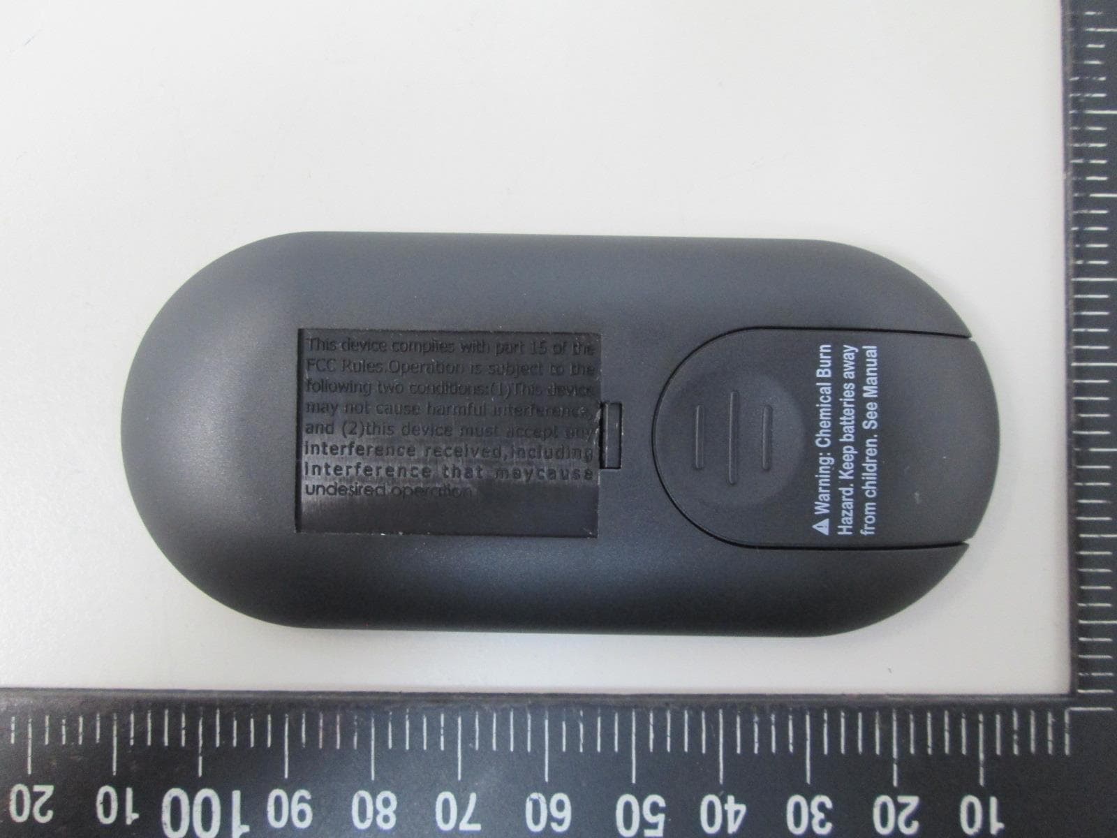
Click to zoom
Application Details
- Equipment Class
- DSC - Part 15 Security/Remote Control Transmitter
- Date of Grant
- Jul 30, 2020
- Application Purpose
- Original Equipment
- Date of Application
- Jul 30, 2020
- Equipment Note
- Remote Controller
- Frequency Range
- 433.90800000 - 433.90800000
- Company
- HOTECK INC.
- Country
- Taiwan
Documents & Files
Document Text
Text extracted from the exhibit documents filed with the FCC. Open a document above to read the original.
Users Manual
6 Speeds Fan Controller HT-01 RL-167 POWER:AC 120V 60 Hz RATING: 100W FOR AC MOTOR FAN 100 W FOR LIGHT Thank you and we are delighted you have chosen the 6 Speed Fan controller for your home please read all instructions carefully before assembly and use. 1 7. This product is for indoor use only. 8. This product requires 120 Vac 60 Hz power supply. 9. This product is to be used only for controlling a ceiling fan with an A.C. (Alternating Current) motor. 10. Do not pull or cut short lead wires. 11. Do not drop or bump the remote controller set. 12. Do not use this remote controller in conjunction with any variable (rheostat) wall controller. 13. Do not use the remote controller transmitter (handset) with any other receiver. 14. Keep battery out of reach of children. 15. This manual is not intended to instruct or assist untrained or unqualified persons to install this remote controller. 16. It is the responsibility of qualified, licensed installer and user to apply common sense and care at all times during installation and operation. INSTALLATION INSTRUCTIONS Make sure electricity is turned off at the main power box before commencing work. Turn off the power by removing fuse or turning off circuit breaker before installing remote controller. 3 SAFETY PRECAUTIONS Please observe the following general safety precautions carefully before and during all phases of handling, installation, removal, operation and maintenance of this product. Failure to comply with these precautions violates safety standards of design, manufacture and intended use of the product. We assumes no liability for customer’s failure to comply with these requirements. SAFETY WARNINGS 1. Read all instructions and safety information. Review assembly diagrams provided before installing your new ceiling fan. 2. This remote controller must be installed according to local authority regulations. 3. This product is not intended for use by persons (including children) with reduced physical, sensory or mental capabilities, or lack of experience and knowledge, unless they have been given supervision or instruction concerning use of the appliance by a person responsible for their safety. 4. Young children should be supervised to ensure that they do not play with the appliance. 5. All electrical works must only be undertaken after disconnection of the power by removing fuses or turning off the circuit breaker, to ensure all pole isolation of the electrical supply. 6. Do not use outdoors where it could be exposed to water or moisture. 2 READ BEFORE INSTALLATION 1. Power supply to input wires of remote controller receiver must be connected through an isolation switch (e.g. wall switch). 2. Install remote controller receiver inside ceiling fan canopy to ensure proper protection. 3. Set ceiling fan speed control rotary switch (if any) to HIGH setting and control switch for light kit (if any) to ON position before operating remote control functions. 4. For ceiling fan with pull chain switches, set pull chain switches accordingly so that ceiling fan speed setting is at HIGH and fan light setting (if any) is at ON position before operating remote control functions. 5. Battery will weaken over time and should be replaced before leaking takes place as this will damage the transmitter. Dispose of used battery properly. 6. If remote controller is to be used for controlling a ceiling fan (i) with a low profile (hugger) design, or (ii) that has a smaller hanging bracket, then you should make sure the hanging bracket will fit remote controller receiver. Otherwise, if the receiver cannot be inserted into the hanging bracket due to dimension limitations or because there is no hanging bracket as may be in the case of a low profile (hugger design) ceiling fan, then the receiver can be enclosed in an Electrical Insulation Box (installation must comply to Australian wiring regulations) and placed in the ceiling. Electrical Insulation Box is not supplied. In this case, remember to draw the antenna / aerial wire away from the insulation box through a small hole. 4 HOW TO INSTALL REMOTE CONTROLLER ID CODE LEARNING Each transmitter (handset) of this remote controller carries a unique Identity Code (ID Code) to facilitate communication between paired devices. The ID Code is set by factory and is not user changeable. The length of ID Code allows up to a million different code combinations, enabling independent control of multiple fans installed within a close proximity. A remote receiver must undergo an “ID code learning” process before it recognises and can communicate with the remote handset. However, you will be required to perform an “ID code learning” process manually under these circumstances: • When you have multiple fans installed within a close proximity and want to control all fans using a same remote transmitter. Note: Each fan requires its own receiver • When your remote controller is not responding (make sure battery is not flat) • After you have replaced a faulty transmitter or receiver with a new one. Otherwise the remote controller will not work. To perform this process manually, follow below steps: INSTRUCTION: Turning on the AC power to the remote receiver, press and hold the transmitter “ FAN ” button for 5 seconds until the receiver beeps to indicate the code learning process had been completed. This operation must be completed within 1 minute after turning on the AC power. 5 FUNCTIONS FAN CONTROL FAN ON/OFF: Press to turning fan on or off SPEED: Press Up or Down key to set 1-6 fan speed . LIGHT SETTING: Before first use, set the slide switch position to "on" side if the light without dimming funtion. set the slide switch position to "DIM" side if the light with dimming funtion. NOTICE: If the light is not dimmable DO NOT slide the switch to right position, It may cause the light to flicker LIGHT CONTROL Press light key to Turing Light On or Off Press and hold light key to dimming light brightness or you can press 4 instant keys to set the bri…
Text truncated - open the document above for the full version.
Cover Letter(s)
SCS-F18: Project and Product Certification Representative Authorization Letter Page 1 of 2 Rev 6.0 775 Montague Expressway Milpitas, CA 95035 Tel: 408-526-1188 Fax: 408-526-1088 Email: [email protected] Project and Product Certification Representative Authorization Letter Reason for Amendment (current / obsolete) Revision History Approved Date From To Initial Release (obsolete) 1.0 1.0 Nov-14-2006 Revised wording (obsolete) 1.0 2.0 Sept–25-2007 Updated company template (obsolete) 2.0 3.0 Jan-31-2012 Updated letter information (obsolete) 3.0 4.0 May-23-2014 Added FCC ID field (obsolete) 4.0 5.0 Sep-16-2014 Updated company name & logo (current) 5.0 6.0 Jun-27-2018 SCS-F18: Project and Product Certification Representative Authorization Letter Page 2 of 2 Rev 6.0 (Jul. 15, 2020) To: BVCPS, INC. 775 Montague Expressway, Milpitas, CA 95035 USA Dear Sir/Madam, Re: Product Certification Representative Authorization Letter We, Intertek Testing Services Taiwan Ltd. hereby authorize Bureau Veritas Consumer Product Services, Inc. to act as a Certification Body for certifying for the following project(s): FCC ID: 2AWBS20085 Product Description: Remote Controller Model: HTT20085A0, HTT20085B0, HTT20085B1, HTT20085B2 Sincerely, Rico Deng/ Supervisor Intertek Testing Services Taiwan Ltd., Hsinchu Laboratory No. 11, Lane 275, Ko-Nan 1 Street, Chia-Tung Li, Shiang-Shan District, Hsinchu City, Taiwan
Cover Letter(s)
HOTECK INC. Date: 2020/7/22 To: BVCPS Inc. 775 Montague Expressway Milpitas, CA 95035 USA RE: New Family Listing Declaration Please review the attached exhibits supporting our request for applying New Family Listing to the FCC ID: 2AWBS20085 for Company Name: HOTECK INC. Product Description: Remote Controller Base model: HTT20085A0 Additional model(s): HTT20085B0,HTT20085B1,HTT20085B2 Should you have any questions, please contact us. Sincerely, Name: Kent Huang Title: Manager Signature:
External Photos
External photo of EUT External photo of EUT External photo of EUT External photo of EUT External photo of EUT
ID Label/Location Info
FCC ID & IC Label Location
Internal Photos
Internal photo of EUT Internal photo of EUT Antenna
Test Report
HOTECK INC. TEST REPORT REPORT NUMBER 200500176TWN-001 ISSUE DATE Jul. 22, 2020 PAGES 21 © 2020 INTERTEK Intertek Report No.: 200500176TWN-001 Page: 1 of 21 This report is for the exclusive use of Intertek's Client and is provided pursuant to the agreement between Intertek and its Client. Intertek's responsibility and liability are limited to the terms and conditions of the agreement. Intertek assumes no liability to any party, other than to the Client in accordance with the agreement, for any loss, expense or damage occasioned by the use of this report. Only the Client is authorized to permit copying or distribution of this report and then only in its entirety. Any use of the Intertek name or one of its marks for the sale or advertisement of the tested material, product or service must first be approved in writing by Intertek. The observations and test results in this report are relevant only to the sample tested. This report by itself does not imply that the material, product, or service is or has ever been under an Intertek certification program. Test Report 0597 Radio Spectrum TEST REPORT Applicant: HOTECK INC. 1F, No. 82, Sancun Rd., Fengyuan Dist., Taichung City 42047 Taiwan Product: Remote Controller Model No.: HTT20085A0, HTT20085B0, HTT20085B1, HTT20085B2 FCC ID: 2AWBS20085 Brand Name: NIL Test Method/ Standard: 47 CFR FCC Part 15.231 Test By: Intertek Testing Services Taiwan Ltd., Hsinchu Laboratory No. 11, Lane 275, Ko-Nan 1 Street, Chia-Tung Li, Shiang-Shan District, Hsinchu City, Taiwan Prepared and Checked by: Approved by: Mark Chang Engineer Durant Wei Engineer Intertek Report No.: 200500176TWN-001 Page: 2 of 21 TEST REPORT Revision History Report No. Issue Date Revision Summary 200500176TWN-001 Jul. 22, 2020 Original report Intertek Report No.: 200500176TWN-001 Page: 3 of 21 TEST REPORT Table of Contents Summary of Test Data ................................................................................................................ 4 1. General Information ............................................................................................................... 5 1.1 Identification of the EUT .................................................................................................. 5 1.2 Additional Information about the EUT ............................................................................. 5 1.3 Antenna description ......................................................................................................... 5 2. Test specifications ................................................................................................................... 6 2.3 Peripherals equipment ..................................................................................................... 6 3. Radiated emission test FCC 15.231 (b) ................................................................................... 7 3.2.1 Radiated emission from 9kHz to 30MHz uses Loop Antenna: ...................................... 7 3.2.2 Radiated emission below 1GHz using Bilog Antenna .................................................... 8 3.2.3 Radiated emission above 1GHz using Horn Antenna .................................................... 8 4. Measured bandwidth FCC 15.231(C) .................................................................................... 17 5. Timing requirement of manual activation operated transmitter ........................................ 18 6. Conducted emission FCC 15.207 .......................................................................................... 19 Appendix A: Test equipment list ............................................................................................... 20 Appendix B: Measurement Uncertainty ................................................................................... 21 Intertek Report No.: 200500176TWN-001 Page: 4 of 21 TEST REPORT Summary of Test Data Test Requirement Applicable Rule Result Radiated Emission test 15.231(b), 15.209 Pass Measured bandwidth 15.231(c) Pass Timing requirement of manually operated transmitter 15.231(a)(1) Pass Conducted Emission test 15.207 N/A Antenna Requirement 15.203 Pass Note: Please note that the test results with statement of conformity, the decision rules which are based on: Safety Testing: the specification, standard or IEC Guide 115. Other Testing: the specification, standard and not taking into account the measurement uncertainty. Intertek Report No.: 200500176TWN-001 Page: 5 of 21 TEST REPORT 1. General Information 1.1 Identification of the EUT Product: Remote Controller Model No.: HTT20085A0 Operating Frequency: 433.908 MHz Channel Number: Single channel Access scheme: DSSS Rated Power: DC 3V from battery Power Cord: N/A Sample receiving date: May 26, 2020 Sample condition: Workable Test Date(s): May 27, 2020 ~ Jun. 16, 2020 1.2 Additional Information about the EUT The customer confirmed the models listed as below were series model to model HTT20085A0 (EUT), the difference between main model and series model are listed as below. Model Number Different HTT20085A0 Black/ With out reversed Key / Dim key HTT20085B0 Black/With reversed Key (Disable)/ Timer key HTT20085B1 White/With reversed Key (Disable)/ Timer key HTT20085B2 Black/With reversed Key(Enable) / Timer key 1.3 Antenna description Antenna Type : Printed antenna Connector Type : Fixed Intertek Report No.: 200500176TWN-001 Page: 6 of 21 TEST REPORT 2. Test specifications 2.1 Test standard The EUT was performed according to the procedures in FCC Part 2.1053 and the requirement in FCC Part 15 Subpart C Section 15.231. 2.2 Operation mode TX mode: Press EUT button to transmit. The signal is maximized through rotation and placement in the three orthogonal axes. X axis Y axis Z axis After verifying three axes, we found the maximum electromagnetic field was occurred at X axis. The final test data was executed under this configuration. 2.3 Peripherals equipment Peripherals Brand Model No. Serial N…
Text truncated - open the document above for the full version.
Test Setup Photos
Radiated Emission Test set-up photo 9kHz~30MHz Radiated Emission Test set-up photo 30MHz~1GHz Radiated Emission Test set-up photo Above 1GHz
Contact Information
Applicant
Kent Huang(Manager)
Test Firm
Intertek Testing Services Taiwan Ltd.Lily Shih
Technical Specifications
| # | Rule Parts | Frequency Range | Power Output |
|---|---|---|---|
| 1 | 15.231 | 433.908 MHz - 433.908 MHz | - |