Text extracted from the exhibit documents filed with the FCC. Open a document above to read the original.
Designed by HiVi Acoustics, Inc. Swans D300 Active Speaker Manual CMIIT ID: 2019DP12468 Due to the reasons in the change of design or others, product information contained here may not be in conformity with product itself. We reserve the right of no prior notice before change. HiVi USA E-mail: [email protected] https://swanspeakers.com HiVi China HiVi Acoustics Technology Co., Ltd. NO.1, South Dongcheng Road, Liangang Industrial Zone, Zhuhai, Guangdong, P.R.China HiVi Acoustics, Inc. 1 IMPORTANT SAFETY INSTRUCTIONS WARNING To reduce the risk of fire or electric shock, do not expose this apparatus to rain or moisture. The lightning flash is intended to alert you to the presence of uninsulated “dangerous voltage” within the product’s enclosure that may be of sufficient magnitude to constitute an electric shock to persons. The exclamation point is intended to alert you to the presence of important operating and maintenance (servicing) instructions in the literature accompanying the appliance. Before connecting or using this apparatus, do read carefully all safety warning and instructions. Please keep this instruction for future reference. This device should be installed or set up in a position that ventilation can be assured. Never put the device in a place that air flow over the ventilation openings might be hindered, such as in a bookshelf or a drawer. This product should be operated only from the type of power source indicated on the back panel of the device. The power cord of this product should be restored in a place that is less possibly be walked on or get pierced, especially its plug, convenience receptacles and the point where power cord exit from the apparatus. Before cleaning this product, make sure the plug is disconnected from the outlet. Proceed with the cleaning in the way that this instruction recommends only. When this product is not in use for a long time, make sure to unplug the power cord from the AC outlet. If below problem happens, send this product to a qualified service personnel for repairing. A. Power cord or power plug is damaged. B. Objects have fallen or liquid has been spilled into this product. C. This product is exposed to rain or other liquid. D. This product functions abnormally or very poorly. E. This product has been dropped or has a damaged enclosure. Never to attempt to repair this product by yourself. Refer all servicing to a qualified servicing personnel. CAUTION To reduce the risk of electric shock, the power plug must be completely inserted into an AC outlet. This product does not contain any parts or components that can be repaired by users themselves. Do not open the enclosure, otherwise it may result in an electric shock. Refer all servicing to a qualified servicing personnel. When you unplug this product from AC outlet, do hold the power plug and pull. Do not pull the power cord. Do not overload AC outlets or the extension cord, as this can lead to risk of fire or electric shock. DO NOT OPEN RISK OF ELECTRIC SHOCK CAUTION Warning 92 Trouble Shooting 1. If there is problem with sound quality. a) Check if all the drivers are working. b Check that audio cables are firmly connected at both ends. 2. If there is no sound from either of the speakers: a Check if the device is on and if a source is playing. b Check if the volume is not on minimum. c Check if there is broken or short circuit with the cable connecting speakers and audio source. ) ) ) ) 3. If there is no sound coming from one of the speakers: a) Check the setting of the audio source. b) Check that all the audio cable are firmly connected at both ends. Break-in is the procedure which can enable the speakers to perform best acoustically. A period ranging from 48-100 hours of usage is recommended before both the amplifier and speaker drivers behave optimally. Alternatively, you can listen 2 or 3 hours every day at a medium volume, and the speakers will be broken-in one month or so. a) Avoid magnetic disturbance. b) Do not place under the sunshine for a long time. c) Do not place in high temperature or moist environment for a long time. d) Do not touch the drivers with your hands. e) Avoid corrosive liquids and gases. a) b) c) d) e) Maintenance Break-in When repairing or replacement of parts is required, make sure the service technician has used the parts/components specified by the manufacturer or parts/components that have the same characteristics as the original parts/components. Unauthorized substitutions may result in risk of fire, electric shock or other hazards. POWER SOURCE Before connecting this product with AC outlet, do check and make sure the electric supply voltage is as same as it is marked on the rear panel of this product. WARNING: It's very dangerous to insert a power plug that has bare wire into an AC outlet. DECLARATION This product does not contain any parts or components that can be repaired by users themselves. If there is any malfunction, refer to this instruction or ask for repair by a qualified service technician. Do not try to repair by yourself, otherwise the manufacturer will not be responsible for any consequences resulted there from. This device complies with Part 15 of the FCC Rules. Operation is subject to the following two conditi ons: (1) This device may not cause harmful interference, and (2) this device must accept any interfere nce received, including interference that may cause undesired operation. NOTE 1: This equipment has be en tested and found to comply with the limits for aClass B digital device, pursuant to Part 15 of the FCC Rules. These limits are designed to provide reasonable protection against harmful interference i n a residential installation. This equipment generates uses and can radiate radiofrequency energy and , if not installed and used in accordance with theinstructions, may cause harmful interference to rad io communications. However,there is no guarantee that interference will not occur in a particular ins tallation. If this equipme…
Text truncated - open the document above for the full version.
Report No.: W EXHIBI EUT View 1 EUT View 2 WTX20X040 T 2 - EUT 1 2 23025W-1 T EXTER RNAL PH HOTOGR APHS Model: FCC Swans D300 Part 15.247 Report No.: W EUT View 3 EUT View 4 WTX20X040 3 4 23025W-1 Model: FCC Swans D300 Part 15.247 Report No.: W EUT View 5 EUT View 6 WTX20X040 5 6 23025W-1 Model: FCC Swans D300 Part 15.247 Report No.: W EUT View 7 EUT View 8 WTX20X040 7 8 23025W-1 Model: FCC Swans D300 Part 15.247 Report No.: W EUT View 9 EUT View 1 WTX20X040 9 10 23025W-1 Model: FCC Swans D300 Part 15.247 Report No.: W EUT View 1 EUT View 1 WTX20X040 11 12 23025W-1 Model: FCC Swans D300 Part 15.247 Report No.: W EUT View 1 WTX20X040 13 23025W-1 Model: FCC Swans D300 Part 15.247
Report No.: W EXHIB Proposed Specificatio n silk-screened Proposed WTX20X040 BIT 1 - P FCC ID La ns: Text is b d onto the EU Label Loca 23025W-1 RODUCT abel Forma black in colo UT or shall be ation on EU T LABEL at r and justifie e affixed at a UT FCC LING ed. Labels ar conspicuous ID Label Lo re printed in location on t cation indelible ink the EUT. Model: FCC k on perman Swans D300 Part 15.247 nent adhesivee
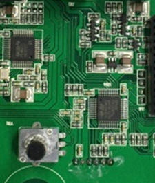
Report No.: W EXHIBI EUT Housi n EUT Housi n WTX20X040 T 3 - EUT ng and Boar ng and Boar 23025W-1 T INTER rd View 1 rd View 2 NAL PHO OTOGRA APHS Model: FCC Swans D300 Part 15.247 Report No.: W EUT Housi n EUT Housi n WTX20X040 ng and Boar ng and Boar 23025W-1 rd View 3 rd View 4 Model: FCC Swans D300 Part 15.247 Report No.: W Solder Boa r Solder Boa r WTX20X040 rd-Compone rd-Compone 23025W-1 ent View 1 ent View 2 Model: FCC Swans D300 Part 15.247
Report No.: W Solder Boa r Solder Boa r WTX20X040 rd-Compone rd-Compone 23025W-1 ent View 3 ent View 4 Model: FCC Swans D300 Part 15.247 Report No.: W Solder Boar d Solder Boa r WTX20X040 d-Componen rd-Compone 23025W-1 nt View 5 ent View 6 Model: FCC Swans D300 Part 15.247 Report No.: W Remote con Remote con WTX20X040 ntrol Solder B ntrol Solder B 23025W-1 Board-Comp Board-Comp ponent View ponent View 1 2 Model: FCC Swans D300 Part 15.247 Report No.: W Antenna Vi WTX20X040 iew 23025W-1 BT Ante enna Model: FCC Swans D300 Part 15.247
1. MAXIMUM PERMISSIBLE EXPOSURE (MPE) 1.1 General Information Client Information Applicant: HiVi Acoustics Technology Co., Ltd. Address of applicant: NO.1, South Dongcheng Road, Liangang Industrial Zone, Zhuhai, Guangdong, P.R.China Manufacturer: HiVi Acoustics Technology Co., Ltd. Address of manufacturer: NO.1, South Dongcheng Road, Liangang Industrial Zone, Zhuhai, Guangdong, P.R.China General Description of EUT: Product Name: Active Speaker Trade Name: Model No.: Swans D300 Adding Model(s): HiVi D300 FCC ID: 2AWE2-D300 Rated Voltage: AC120V~ 60Hz Technical Characteristics of EUT: Bluetooth Version: V5.0 (BR/EDR mode) Frequency Range: 2402-2480MHz RF Output Power: -1.48dBm (Conducted) Data Rate: 1Mbps, 2Mbps, 3Mbps Modulation: GFSK, Pi/4 DQPSK, 8DPSK Quantity of Channels: 79 Channel Separation: 1MHz Type of Antenna: Integral Antenna Gain: 3.89 dBi 1.2 Standard Applicable According to §1.1307(b)(1) and KDB 447498 D01 General RF Exposure Guidance v06, system operating under the provisions of this section shall be operating in a manner that the public is not exposed to radio frequency energy level in excess limit for maximum permissible exposure. (a) Limits for Occupational / Controlled Exposure Frequency range (MHz) Electric Field Strength (E) (V/m) Magnetic Field Strength (H) (A/m) Power Density (S) (mW/cm 2 ) Averaging Times | E | 2 , | H | 2 or S (minutes) 0.3-3.0 614 1.63 (100)* 6 3.0-30 1842/f 4.89/f (900/f)* 6 30-300 61.4 0.163 1.0 6 300-1500 / / F/300 6 1500-100000 / / 5 6 (b) Limits for General Population / Uncontrolled Exposure Frequency range (MHz) Electric Field Strength (E) (V/m) Magnetic Field Strength (H) (A/m) Power Density (S) (mW/cm 2 ) Averaging Times | E | 2 , | H | 2 or S (minutes) 0.3-1.34 614 1.63 (100)* 30 1.34-30 824/f 2.19/f (180/f)* 30 30-300 27.5 0.073 0.2 30 300-1500 / / F/1500 30 1500-100000 / / 1 30 Note: f = frequency in MHz: * = Plane-wave equivalents power density 1.3 MPE Calculation Method S = (30*P*G) / (377*R 2 ) S = power density (in appropriate units, e.g., mw/cm 2 ) P = power input to the antenna (in appropriate units, e.g., mw) G = power gain of the antenna in the direction of interest relative to an isotropic radiator, the power gain factor is normally numeric gain. R = distance to the center of radiation of the antenna (in appropriate units, e.g., cm) 1.4 MPE Calculation Result Maximum Tune-Up output power: -1(dBm) Maximum peak output power at antenna input terminal:0.79(mW) Prediction distance: >20(cm) Prediction frequency: 2480 (MHz) Antenna gain:3.89(dBi) Directional gain (numeric gain): 2.45 The worst case is power density at prediction frequency at 20cm: 0.0004(mw/cm 2 ) MPE limit for general population exposure at prediction frequency: 1 (mw/cm 2 ) Result: Pass
Model: Swans D300 Report No.: WTX20X04023025W-1 Page 1 of 55 FCC Part 15.247 FCC Part 15C Measurement and Test Report For HiVi Acoustics Technology Co., Ltd. NO.1, South Dongcheng Road, Liangang Industrial Zone, Zhuhai, Guangdong, P.R.China FCC ID: 2AWE2-D300 FCC Rule(s): FCC Part 15.247 Product Description: Active Speaker Tested Model: Swans D300 Report No.: WTX20X04023025W-1 Sample Receipt Date: Apr.28, 2020 Tested Date: Apr.28, 2020 to May.22, 2020 Issued Date: May.22, 2020 Tested By: Mike Shi / Engineer Reviewed By: Lion Cai / RF Manager Approved & Authorized By: Silin Chen / Manager Prepared By: Waltek Testing Group (Shenzhen) Co., Ltd. 1/F., Room 101, Building 1, Hongwei Industrial Park, Liuxian 2nd Road, Block 70 Bao'an District, Shenzhen, Guangdong, China Tel.: +86-755-33663308 Fax.: +86-755-33663309 Website: www.semtest.com.cn Note: This test report is limited to the above client company and the product model only. It may not be duplicated without prior permitted by Waltek Testing Group (Shenzhen) Co., Ltd. Model: Swans D300 Report No.: WTX20X04023025W-1 Page 2 of 55 FCC Part 15.247 TABLE OF CONTENTS 1. GENERAL INFORMATION ................................................................................................................................... 4 1.1 PRODUCT DESCRIPTION FOR EQUIPMENT UNDER TEST (EUT) ............................................................................... 4 1.2 TEST STANDARDS ................................................................................................................................................... 5 1.3 TEST METHODOLOGY ............................................................................................................................................. 5 1.4 TEST FACILITY ....................................................................................................................................................... 5 1.5 EUT SETUP AND TEST MODE ................................................................................................................................. 6 1.6 MEASUREMENT UNCERTAINTY .............................................................................................................................. 7 1.7 TEST EQUIPMENT LIST AND DETAILS ..................................................................................................................... 8 2. SUMMARY OF TEST RESULTS ......................................................................................................................... 10 3. RF EXPOSURE ....................................................................................................................................................... 11 3.1 STANDARD APPLICABLE ....................................................................................................................................... 11 3.2 TEST RESULT........................................................................................................................................................ 11 4. ANTENNA REQUIREMENT ................................................................................................................................ 12 4.1 STANDARD APPLICABLE ....................................................................................................................................... 12 4.2 EVALUATION INFORMATION ................................................................................................................................ 12 5. FREQUENCY HOPPING SYSTEM REQUIREMENTS ................................................................................... 13 5.1 STANDARD APPLICABLE ....................................................................................................................................... 13 5.2 FREQUENCY HOPPING SYSTEM............................................................................................................................. 13 5.3 EUT PSEUDORANDOM FREQUENCY HOPPING SEQUENCE .................................................................................... 14 6. QUANTITY OF HOPPING CHANNELS AND CHANNEL SEPARATION ................................................... 15 6.1 STANDARD APPLICABLE ....................................................................................................................................... 15 6.2 TEST PROCEDURE ................................................................................................................................................. 15 6.3 SUMMARY OF TEST RESULTS/PLOTS .................................................................................................................... 15 7. DWELL TIME OF HOPPING CHANNEL .......................................................................................................... 19 7.1 STANDARD APPLICABLE ....................................................................................................................................... 19 7.2 TEST PROCEDURE ................................................................................................................................................. 19 7.3 SUMMARY OF TEST RESULTS/PLOTS .................................................................................................................... 20 8. 20DB BANDWIDTH ............................................................................................................................................... 27 8.1 STANDARD APPLICABLE ....................................................................................................................................... 27 8.2 TEST PROCEDURE ................................................................................................................................................. 27 8.3 SUMMARY OF TEST RESULTS/PLOTS .................................................................................................................... 28 9. RF OUTP…
Text truncated - open the document above for the full version.
Report No.: W EXHIBI Conducted Radiation E WTX20X040 T 4 - TES Emission Te Emission Tes 23025W-1 ST SETUP est Setup st Setup (Belo P PHOTO ow 30MHz) OGRAPH HS Model: FCC Swans D300 Part 15.247 Report No.: W Radiation E Radiation E WTX20X040 Emission Tes Emission Tes 23025W-1 st Setup (30M st Setup (1GH MHz to 1GHz Hz to 18GHz z) z) Model: FCC Swans D300 Part 15.247 Report No.: W Radiation E WTX20X040 Emission Tes 23025W-1 st Setup (Abo ove 18GHz) Model: FCC Swans D300 Part 15.247
| # | Rule Parts | Frequency Range | Power Output |
|---|---|---|---|
| 1 | 15C | 2.40 GHz - 2.48 GHz | 700.00 µW |

High Fidelity Active Speaker
Equipment Class
DSS - Part 15 Spread Spectrum Transmitter