2AWH4-NH3294HTWIRELESS CHARGING CROSSOVER
LACOSTE OPERATIONS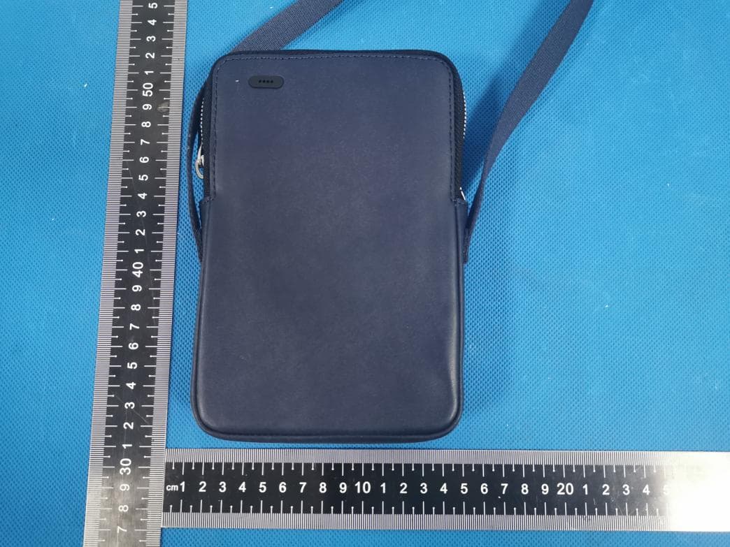
Click to zoom
Application Details
- Equipment Class
- DCD - Part 15 Low Power Transmitter Below 1705 kHz
- Date of Grant
- Jun 04, 2020
- Application Purpose
- Original Equipment
- Date of Application
- Jun 04, 2020
- Equipment Note
- WIRELESS CHARGING CROSSOVER
- Frequency Range
- 0.11100000 - 0.17500000
- Company
- LACOSTE OPERATIONS
- Country
- France
Documents & Files
Document Text
Text extracted from the exhibit documents filed with the FCC. Open a document above to read the original.
Users Manual
LACOSTE - WIRELESS CHARGING CROSSOVER Product model : NH3294HT / NF3280HT Lithium-Ion Polymer Rechargeable Battery 5000mAh 3.7V | USB-C Input: 5V 3A | Wireless Output 5W Manufacturer: Shenzhen Aodehong Electronic Technology Co., Ltd. Address: 5th Floor, Elegant Industrial Park, No. 8 Liuhe Road, Liuyue, Henggang Street, Longgang District, Shenzhen, People’s Republic Of China Importer: LACOSTE OPERATIONS Address: 31-37 Boulevard De Montmorency, 75016 PARIS, FRANCE FCC ID: 2AWH4-NH3294HT FCC Class B Information This equipment has been tested and found to comply with the limits for a Class B digital device, pursuant to Part 15 of the FCC Rules. These limits are designed to provide reasonable protection against harmful interference in a residential installation. This equipment generates, uses and can radiate radio frequency energy and, if not installed and used in accordance with the instructions, may cause harmful interference to radio communications. However, there is no guarantee that interference will not occur in a particular installation. If this equipment does cause harmful interference to radio or television reception, which can be determined by turning the equipment off and on, the user is encouraged to try to correct the interference by one of the following measures: -Reorient or relocate the receiving antenna. -Increase the separation between the equipment and receiver. -Connect the equipment into an outlet on a circuit different from that to which the receiver is connected. -Consult the dealer or an experienced radio/TV technician for help. This device complies with Part 15 of the FCC Rules. Operation is subject to the following two conditions: (1) This device may not cause harmful interference, and (2) this device must accept any interference received, including interference that may cause undesired operation. This device and its antenna(s) must not be co-located or operating in conjunction with any other antenna or transmitter. This device has been evaluated to meet general RF exposure requirement. This device can be used in portable exposure condition without restriction. FCC Caution: Any changes or modifications not expressly approved by the party responsible for compliance could void the user’s authority to operate this equipment. WIRELESS CHARGING CROSSOVER Français English Español Português Italiano Deutsch Pусский 中文 日本語 한국의 3-5 6-8 9-11 12-14 15-17 18-20 21-23 24-26 27-29 30-32 Si vous utilisez le produit pour la première fois, recharger entièrement la batterie avec le câble fourni. Dans l’avion, la batterie ne peut être transportée qu’en cabine Attention : Suivez les informations d’avertissement fournies ci-dessous pour éviter des incidents tels qu’un incendie ou une explosion. -Ne pas exposer le produit à des chocs -Ne pas toucher le chargeur ou le produit avec les mains mouillées pendant le chargement du produit -Ne stockez pas votre produit à proximité ou dans des appareils de chauffage, des micro- ondes, des équipements de cuisson ou des récipients à haute pression -Gardez le produit au sec -N’utilisez pas votre produit en plein air pendant un orage -Le produit doit être utilisé dans des endroits où la température ambiante est comprise entre 0 ° C et 35 ° C -Utilisez le produit en dehors des plages de température recommandées peut l’endommager ou réduire la durée de vie de la batterie 3 1RECHARGER LE TÉLÉPHONE Tapez deux fois sur la plaque LED pour allumer le produit. Placez votre téléphone sur la zone de chargement par induction : centré dans la poche intérieure ou directement sur la face avant du sac Après le chargement, tapez à nouveau deux fois sur la plaque métallique pour éteindre le produit. A défaut le produit s’éteindra automatiquement au bout de 25 secondes. OU 4 PLAQUE LED Indicateur de batterie É TAT Nombre de LEDs 30%60% 100% 12 3 Allumé En chargement Erreur RECHARGER LA BATTERIE DU SAC Le câble fourni vous permet de recharger la batterie du sac en branchant la prise USB à un chargeur secteur et l’ USB-C à l’intérieur du produit 2 5 Fully charge the battery with the cable provided the first time you use the product. The battery must be kept in the cabin during flights. Warning : Follow the instructions below to avoid accidents such as fires or explosions. -Do not expose the product to impact -Do not touch the charger or product with wet hands whilst charging the product -Do not store your product in or near heating appliances, microwaves, cooking equipment or high-pressure containers -Keep the product dry -Do not use your product outdoors in stormy weather -The product must be used in places with a temperature between 0 ° C and 35 ° C -Using the product outside the recommended temperature limits may damage it or affect its battery life 6 1CHARGE THE PHONE Tap the LED plate twice to turn the product on. Place your phone on the wireless charging section: centred in the internal pocket or straight on the front of the bag. After charging, tap the metallic plate twice again to turn the product off. The product will automatically turn off after 25 seconds otherwise. OR 7 LED PLATE Battery indicatorStatus number of LEDs 30%60% 100% 12 3 On Charging Error CHARGE THE BAG BATTERY You can use the cable provided to charge the bag battery by plugging the USB socket into the mains charger and the USB-C inside the product. 2 8 Si utiliza el producto por primera vez, recargue la batería completamente con el cable proporcionado. En el avión, la batería solo se puede transportar en cabina. Atención : Siga las advertencias proporcionadas a continuación para evitar accidentes tales como un incendio o una explosión. -No exponer el producto a choques -No tocar el cargador o el producto con las manos mojadas durante la carga del producto -No guardar su producto cerca de aparatos de calefacción, de microondas, de equipos de cocina o recipientes de alta presión. -Guarde el producto en seco -No utilice su producto al aire libre durante una tormenta -El producto debe utilizarse e…
Text truncated - open the document above for the full version.
External Photos
S20040101003 Model: NH3294HT N20190309V1 Photo 1 Photo 2 S20040101003 Model: NH3294HT N20190309V1 Photo 3 Photo 4 S20040101003 Model: NH3294HT N20190309V1 Photo 5 Photo 6 S20040101003 Model: NH3294HT N20190309V1 Photo 7
ID Label/Location Info
Label's location
RF Exposure Info
FCC ID: 2AWH4-NH3294HT 1.Measuring Standard FCC Part 1(1.1310) and Part 2(2.1091), KDB 680106 D01 RF Exposure Wireless Charging App v03 1.2. Requiments Three different categories of transmitters are defined by the FCC in OET Bulletin 65. These categories are fixed installation, mobile, and portable and are defined as follows: o Fixed Installations: fixed location means that the device, including its antenna, is physically secured at a permanent location and is not able to be easily moved to another location. Additionally, distance to humans from the antenna is maintained to at least 2 meters. o Mobile Devices: a mobile device is defined as a transmitting device designed to be used in other than fixed locations and to be generally used in such a way that a separation distance of at least 20 centimeters is normally maintained between the transmitter's radiating structures and the body of the user or nearby persons. Transmitters designed to be used by consumers or workers that can be easily re-located, such as a wireless modem operating in a laptop computer, are considered mobile devices if they meet the 20 centimeter separation requirement. The FCC rules for evaluating mobile devices for RF compliance are found in 47 CFR §2.1091. o Portable Devices: a portable device is defined as a transmitting device designed to be used so that the radiating structure(s) of the device is/are within 20 centimeters of the body of the user. Portable device requirements are found in Section 2.1093 of the FCC's Rules (47 CFR§2.1093). The FCC also categorizes the use of the device as based upon the user’s awareness and ability to exercise control over his or her exposure. The two categories defined are Occupational/ Controlled Exposure and General Population/Uncontrolled Exposure. These two categories are defined as follows: Occupational/Controlled Exposure: In general, occupational/controlled exposure limits are applicable to situations in which persons are exposed as a consequence of their employment, who have been made fully aware of the potential for exposure and can exercise control over their exposure. This exposure category is also applicable when the exposure is of a transient nature due to incidental passage through a location where the exposure levels may be higher than the general population/uncontrolled limits, but the exposed person is fully aware of the potential for exposure and can exercise control over his or her exposure by leaving the area or by some other appropriate means. Awareness of the potential for RF exposure in a workplace or similar environment can be provided through specific training as part of a RF safety program. If appropriate, warning signs and labels can also be used to establish such awareness by providing prominent information on the risk of potential exposure and instructions on methods to minimize such exposure risks. General Population/Uncontrolled Exposure: The general population / uncontrolled exposure limits are applicable to situations in which the general public may be exposed or in which persons who are exposed as a consequence of their employment may not be made fully aware of the potential for exposure or cannot exercise control over their exposure. Members of the general public would come under this category when exposure is not employment-related; for example, in the case of a wireless transmitter that exposes persons in its vicinity. Warning labels placed on low-power consumer devices such as cellular telephones are not considered sufficient to allow the device to be considered under the occupational/controlled category, and the general population/uncontrolled exposure limits apply to these devices. 1.3 Test configuration 1, The field strength of both E-field and H-field was measured at 15cm using the equipment list above for determining compliance with the MPE requirements of FCC Part 1.1310. 2, The RF power density was measured at Under maximum load test 3, Maximum E-field and H-field measurements were made 15cm from each side of the EUT. Along the side of the EUT and still 15cm away from the edge of the EUT, the field probes were positioned at the location where there is maximum field strength. The maximum E-field and H-field is reported below. 4, This device uses a wireless charging circuit for power transfer operating at the frequency of 111–175kHz. Thus, the 300kHz limits were used: E-field Limit = 614 (V/m); H-field limit = 1.63 (A/m). 1.4 Test Setup 2. Limits 3. MEASURING DEVICE AND TEST EQUIPMENT 2.1For MPE Measurement Equipment Manuf acturer Model No. Serial No. Last calibration Calibrated until Cal. Interval E-Field Probe(100kHz-3GHz) Narda EF0391 Q15221 May 16, 2019 May 15, 2020 1 Year H-Field Probe(300KHz-30MHz) Narda HF3061 Q15835 May 16, 2019 May 15, 2020 1 Year Broadband Field Meter Narda NBM-550 Q201455 May 16, 2019 May 15, 2020 1 Year Load N/A N/A N/A N/A N/A N/A 4. Measuring Results EUT: INFINI-T WIRELESS CHARGING CROSSOVER Model Name. : NH3294HT Temperature: 26 °C Relative Humidity: 54% Pressure: 1010hPa Test Date: 2019-05-06 Test Voltage: DC 5V from adapter AC 120V/60Hz Test Mode : Max Load Low frequency: Table 1. H-Field MPE Data-Top EUT Side Top(V/m) Limits (V/m) Max load 0.033 1.63 Table 2. H-Field MPE Data- Surrounding EUT Side Left(A/m) Right(A/m) Bottom (A/m) Z- Axis(above) (A/m) Limits (A/m) Max load 0.013 0.044 0.052 0.042 1.63 Table 3. E-Field MPE E-Field Measurement (15cm) EUT Side Left(V/m) Right(V/m) Top(V/m) Bottom (V/m) Z- Axis(above) (V/m) Limits (V/m) Max load 2.13 1.93 1.85 1.21 1.01 614 Middle frequency: Table 1. H-Field MPE Data-Top EUT Side Top(V/m) Limits (V/m) Max load 0.032 1.63 Table 2. H-Field MPE Data- Surrounding EUT Side Left(A/m) Right(A/m) Bottom (A/m) Z- Axis(above) (A/m) Limits (A/m) Max load 0.039 0.032 0.027 0.057 1.63 Table 3. E-Field MPE E-Field Measurement (15cm) EUT Side Left(V/m) Right(V/m) Top(V/m) Bottom (V/m) Z- Axis(above) (V/m) Limits (V/m) Max load 2.12 2.03 1.52 1.19 1.15 614 High frequency: T…
Text truncated - open the document above for the full version.
Test Report
Report No.: S20040101003001 Version.1.1 Page 1 of 25 FCC Test Report FCC ID: 2AWH4-NH3294HT Product: WIRELESS CHARGING CROSSOVER Trade Name: LACOSTE Model Number: NH3294HT Family Model: NF3280HT Report No.: S20040101003001 Prepared for LACOSTE OPERATIONS 31-37 BOULEVARD DE MONTMORENCY 75016 PARIS, FRANCE Prepared by Shenzhen NTEK Testing Technology Co., Ltd. 1/F, Building E, Fenda Science Park, Sanwei Community, Xixiang Street, Bao’an District, Shenzhen P.R. China Tel.: +86-0755-61156588 Fax.: +86-0755-61156599 Website: www.ntek.org.cn Report No.: S20040101003001 Version.1.1 Page 2 of 25 TEST RESULT CERTIFICATION Applicant’s name ................. : LACOSTE OPERATIONS Address ................................. : 31-37 BOULEVARD DE MONTMORENCY 75016 PARIS, FRANCE Manufacturer's Name .......... : Shenzhen Aodehong Electronic Technology Co., Ltd. Address ................................. : 5th Floor, Elegant Industrial Park, No. 8 Liuhe Road, Liuyue, Henggang Street, Longgang District, Shenzhen, China Product description Product name............................ : WIRELESS CHARGING CROSSOVER Model and/or type reference : NH3294HT, NF3280HT Standards ............................. : FCC part 15C ANSI C63.10:2013 KDB 680106 D01 RF Exposure Wireless Charging App v03 This device described above has been tested by Shenzhen NTEK Testing Technology Co., Ltd., and the test results show that the equipment under test (EUT) is in compliance with the FCC requirements. And it is applicable only to the tested sample identified in the report. This report shall not be reproduced except in full, without the written approval of Shenzhen NTEK Testing Technology Co., Ltd., this document may be altered or revised by Shenzhen NTEK Testing Technology Co., Ltd., personnel only, and shall be noted in the revision of the document. The test results of this report relate only to the tested sample identified in this report. Date of Test ........................................... : Date (s) of performance of tests ............. : 04 Apr. 2020 ~ 30 Apr. 2020 Date of Issue .......................................... : 08 May. 2020 Test Result.............................................. : Pass Testing Engineer : (Mary Hu) Technical Manager : (Jason Chen) Authorized Signatory : (Sam Chen) Report No.: S20040101003001 Version.1.1 Page 3 of 25 Table of Contents Page 1 . TEST SUMMARY 4 1.1 FACILITIES AND ACCREDITATIONS 5 1.2 LABORATORY ACCREDITATIONS AND LISTINGS 5 1.3 MEASUREMENT UNCERTAINTY 5 2 . GENERAL INFORMATION 7 2.1 GENERAL DESCRIPTION OF EUT 7 2.2 DESCRIPTION OF TEST SETUP 9 2.3 DESCRIPTION TEST PERIPHERAL AND EUT PERIPHERAL 10 2.4 MEASUREMENT INSTRUMENTS LIST 11 3 . EMC EMISSION TEST 12 3.1 CONDUCTED EMISSION MEASUREMENT 12 3.1.1 POWER LINE CONDUCTED EMISSION 12 3.1.2 TEST PROCEDURE 13 3.1.3 TEST SETUP 13 3.1.4 EUT OPERATING CONDITIONS 13 3.1.5 TEST RESULTS 14 3.2 RADIATED EMISSION MEASUREMENT 16 3.2.1 LIMITS OF RADIATED EMISSION MEASUREMENT 16 3.2.2 TEST PROCEDURE 17 3.2.3 TEST SETUP 18 3.2.4 TEST RESULTS 19 4. BANDWIDTH TEST 24 4.1 TEST PROCEDURE 24 4.2 TEST SETUP 24 4.3 TEST RESULT 24 5. ANTENNA APPLICATION 25 5.1 Antenna Requirement 25 5.2 Result 25 Report No.: S20040101003001 Version.1.1 Page 4 of 25 1. TEST SUMMARY Test procedures according to the technical standards: EMC Emission Standard Test Item FCC Rules Limit Judgment Remark FCC part 15C:2018 ANSI C63.10:2013 Conducted Emission §15.207 Class B PASS Radiated Emission §15.209 Class B PASS ANTENNA APPLICATION §15.203 / PASS NOTE: (1) ’N/A’ denotes test is not applicable in this Test Report (2) For client’s request and manual description, the test will not be executed. Report No.: S20040101003001 Version.1.1 Page 5 of 25 1.1 FACILITIES AND ACCREDITATIONS All measurement facilities used to collect the measurement data are located at 1/F, Building E, Fenda Science Park, Sanwei Community, Xixiang Street, Bao’an District, Shenzhen 518126 P.R. China. The sites are constructed in conformance with the requirements of ANSI C63.7, ANSI C63.10 and CISPR Publication 22. 1.2 LABORATORY ACCREDITATIONS AND LISTINGS Site Description CNAS-Lab. : The Laboratory has been assessed and proved to be in compliance with CNAS-CL01:2006 (identical to ISO/IEC 17025:2005) The Certificate Registration Number is L5516. IC-Registration : The Certificate Registration Number is 9270A-1. FCC- Accredited : Test Firm Registration Number: 463705. Designation Number: CN1184 A2LA-Lab. : The Certificate Registration Number is 4298.01 This laboratory is accredited in accordance with the recognized International Standard ISO/IEC 17025:2005 General requirements for the competence of testing and calibration laboratories. This accreditation demonstrates technical competence for a defined scope and the operation of a laboratory quality management system (refer to joint ISO-ILAC-IAF Communiqué dated 8 January 2009). Name of Firm : Shenzhen NTEK Testing Technology Co., Ltd. Site Location : 1/F, Building E, Fenda Science Park, Sanwei Community, Xixiang Street, Bao’an District, Shenzhen 518126 P.R. China. 1.3 MEASUREMENT UNCERTAINTY The reported uncertainty of measurement y ± U, where expended uncertainty U is based on a standard uncertainty multiplied by a coverage factor of k=2, providing a level of confidence of approximately 95 %. A. Conducted Measurement : Test Site Method Measurement Frequency Range U,(dB) NOTE NTEKC01 ANSI 150 KHz ~ 30MHz 3.2 B. Radiated Measurement : Test Site Method Measurement Frequency Range U,(dB) NOTE NTEKA01 ANSI 30MHz ~ 1000MHz 4.7 1GHz ~12.4GHz 5.0 Report No.: S20040101003001 Version.1.1 Page 6 of 25 Revision History Report No. Version Description Issued Date S20040101003001 Rev.01 Initial issue of report 08 May. 2020 Report No.: S20040101003001 Version.1.1 Page 7 of 25 2. GENERAL INFORMATION 2.1 GENERAL DESCRIPTION OF EUT Product Feature and Specification Equipment WIRELESS CHARGING CROSSOVER Trade Name LACOSTE FCC ID 2AWH4-NH3294HT Model No. NH3294HT Family Model NF3280HT Mo…
Text truncated - open the document above for the full version.
Test Setup Photos
FCC ID: 2AWH4-NH3294HT Radiated Measurement Photos AC Conducted Measurement Photos
Test Setup Photos
PHOTOGRAPHS OF TEST SETUP 15 cm surrounding 20 cm above the top
Contact Information
Applicant
Emmanuel Tamalet
Test Firm
Shenzhen NTEK Testing Technology Co., Ltd.Alex Li
[email protected]+86-755-6115-9384
Technical Specifications
| # | Rule Parts | Frequency Range | Power Output |
|---|---|---|---|
| 1 | 15C | 0.111 MHz - 0.175 MHz | - |