2AWI6-G2BCCCherry Gen2 Basic Care (Home Camera)
Cherry Labs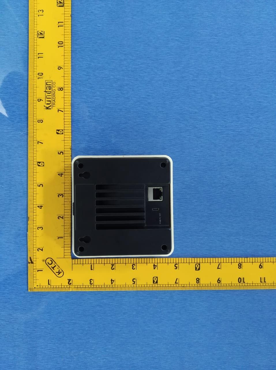
Click to zoom
Application Details
- Equipment Class
- NII - Unlicensed National Information Infrastructure TX
- Date of Grant
- Aug 20, 2020
- Application Purpose
- Original Equipment
- Date of Application
- Jul 29, 2020
- Equipment Note
- Cherry Gen2 Basic Care (Home Camera)
- Frequency Range
- 5745.00000000 - 5825.00000000
- Company
- Cherry Labs
- Country
- United States
Documents & Files
Document Text
Text extracted from the exhibit documents filed with the FCC. Open a document above to read the original.
Users Manual
GEN 2 BASIC CARE User Guide The Home AI that cares for your loved ones. VVDN TECHNOLOGIES PVT LTD | www.vvdntech.com CONFIDENTIAL 1 VVDN_Cherry Gen2 Basic Care_User Manual ©VVDN Technologies Pvt Ltd. 2 Copyright Notice This document is copyright of VVDN Technologies Pvt Ltd, All Rights Reserved. No part of this document, in whole or in part, may be used, reproduced, stored in a retrieval system or transmitted, in any form, or by any means, electronic or otherwise, including photocopying, reprinting, or recording, for any purpose, without the express written permission of VVDN Technologies Pvt Ltd Legal Disclaimer The information contained in this document is subject to change without notice. The information in this document is provided for informational purposes only. VVDN Technologies Pvt Ltd specifically disclaims all warranties, express or limited, including, but not limited, to the implied warranties of merchantability and fitness for a particular purpose, except as provided for in a separate software license agreement. VVDN Technologies VVDN is a technology innovation company providing broad spectrum of embedded design services and ODM capabilities of Networking, Wireless, IOT and Cameras. Headquartered in Gurgaon, India; VVDN combines a passion for client satisfaction, technology innovation, deep industry and business process expertise and a global, collaborative workforce, that embodies the future of work. Being an ISO certified ODM, our main focus is to provide qualitative embedded system solutions. Corporate Office B-22, Infocity 1 Sector-34, Gurgaon-122001, Haryana, India Tel No: +91 124 4284250 US Office Suite# 307, 1735 North First Street, San Jose, California, 95112 E-MAIL [email protected] WEBSITE www.vvdntech.com VVDN_Cherry Gen2 Basic Care_User Manual ©VVDN Technologies Pvt Ltd. 3 Table of Contents 1 About This Document ......................................................................................................... 4 1.1 Intended Audience ................................................................................................................. 4 1.2 Document Conventions ......................................................................................................... 4 2 Overview ............................................................................................................................ 5 3 Accessories ......................................................................................................................... 5 4 Getting Started ................................................................................................................... 6 4.1 Get to know Cherry Cam ........................................................................................................ 6 4.2 Cherry Notification LED Status ............................................................................................... 6 4.3 Installation ............................................................................................................................. 7 5 RTSP Streaming using VLC ................................................................................................... 8 5.1 Steps to pair Cherry cam and stream over VLC .................................................................. 8 6 Product Functional Features .............................................................................................. 11 Table of Figure Figure 1 : Cherry Gen2 Camera ........................................................................................................5 Figure 2 : Cherry Cam Components .................................................................................................6 Figure 3 : Cherry Cam Installation Steps ..........................................................................................7 Figure 4 : Pairing and Reset ..............................................................................................................9 Figure 5 : QR Code Scanning ..........................................................................................................10 Table of Table Table 1 : Document Conventions .....................................................................................................4 Table 2 : Device Accessories ............................................................................................................5 Table 3 : Cherry Notification LED Status ..........................................................................................6 ©VVDN Technologies Pvt Ltd. 4 VVDN_Cherry Gen2 Basic Care_User Manual 1 About This Document This document helps you to understand and operate the Cherry Gen2 Basic Care device. 1.1 Intended Audience The intended audiences for this document are End Users of this product 1.2 Document Conventions The different conventions used in this document are explained in the following table: Document Conventions Convention Description Note Note provides information about important features or instructions. This appears with a background. Table 1: Document Conventions ©VVDN Technologies Pvt Ltd. 5 VVDN_Cherry Gen2 Basic Care_User Manual 2 Overview Cherry Gen2 Basic Care is the AI based IP Camera system, Its AI understands and analyzes what’s going on at Camera and learns people's behaviors to detect accidents and send alerts to the family members and caregivers. Cherry Camera also boasts a unique approach to maintaining people’s privacy, as its computer vision algorithms turn people on video into virtual skeletons while all of the information is processed on-device. Key Features: Smart Detection: Cherry Camera devices have advanced AI that can detect not just basic falls but also complex situations and anomalies, like when a person falls behind an obstacle, changes their gait abruptly, or goes to the bathroom and doesn’t come back. The team developed a unique proprietary training system so Cherry Camera’s AI only needs to see a p…
Text truncated - open the document above for the full version.
Attestation Statements
Cherry Labs 550 Hamilton Avenue, Suite 125 Palo Alto, CA 94301 US [email protected] UNII Declaration Letter We have declared below featured for FCC equipment authorization, device FCC ID: (1) DFS Device -- Master, Client with Radar detection capability , Client without radar detection capability, N/A (2) Active / Passive Scanning , adhoc mode access point capability Frequency Band (MHz) Active Scanning (the device can transmit a probe (beacon)) passive scanning (where the device is can listen only with no probes) Ad Hoc Mode capability Access point capability 2412 – 2462 MHz Yes, No Yes, No Yes, No Yes, No 2422 – 2452 MHz Yes, No Yes, No Yes, No Yes, No 5745 – 5825 MHz Yes, No Yes, No Yes, No Yes, No 5755 – 5795 MHz Yes, No Yes, No Yes, No Yes, No 5180 – 5240 MHz Yes, No Yes, No Yes, No Yes, No 5190 – 5230 MHz Yes, No Yes, No Yes, No Yes, No 5260 – 5320 MHz Yes, No Yes, No Yes, No Yes, No 5270 – 5310 MHz Yes, No Yes, No Yes, No Yes, No 5500 – 5700 MHz Yes, No Yes, No Yes, No Yes, No 5510 – 5670 MHz Yes, No Yes, No Yes, No Yes, No (3) Country code selection ability - Yes , No If no, pls explain how was implemented : use Microsoft network utility (4) Meet 15.202 requirement - pls check below : Yes , No , A master device is defined as a device operating in a mode in which it has the capability to transmit without receiving an enabling signal. In this mode it is able to select a channel and initiate a network by sending enabling signals to other devices A client device is defined as a device operating in a mode in which the transmissions of the device are under control of the master. A device in client mode is not able to initiate a network. (5) For client devices that have software configuration control to operate in different modes (active scanning in some and passive scanning in others) in different bands (devices with multiple equipment classes or those that operate on non-DFS frequencies) or modular devices which configure the modes of operations through software, the application must provide software and operations description on how the software and / or hardware is implemented to ensure that proper operations modes can not be modified by end user or an installer. Apply , No Apply , (If apply , pls help to provide explanation on how it was implement (By hardware or software , and how software was controlled) If you have any questions, please feel free to contact me at the address shown below. Yours sincerely, Signatory Printed Name: Ben Heng Position : Technical Manager
Cover Letter(s)
C5266091_X8_Ed.1 1/1 Letter of Authorization Cherry Labs Company: Cherry Labs Address: 550 Hamilton Ave, Suite 125, Palo Alto, CA 94301,United States Product Name: Cherry Gen2 Basic Care (Home Camera) Model Number: GEN 2 BASIC CARE FCC Identifier: 2AWI6-G2BCC We authorize LGAI Technological Center S.A., Ronda de la Font del Carme, s/n, 08193 Bellaterra, Spain, to act on our behalf on all matters concerning the above named equipment. Any individual within LGAI Technological Center S.A. is authorized to act on our behalf and take action on the application. We declare that authorize LGAI Technological Center S.A., Ronda de la Font del Carme, s/n, 08193 Bellaterra, Spain, is allowed to forward all information related to the approval project to the Federal Communication Commission and to discuss any issues concerning the approval application. Any and all acts carried out by LGAI Technological Center S.A. on our behalf shall have the same effect as acts of our own. Name: Ben Heng Date: 2020/07/30 Title: EVP Operations Signature of applicant:
Cover Letter(s)
C5266091_X10_Ed.2 1/1 Cherry Labs Office of Engineering Technology Federal Communications Commission 7435 Oakland Mills Road Columbia, MD 21046 Date: 2020/07/30 Subject: Request for Confidentiality FCC ID: 2AWI6-G2BCC To Whom It May Concern, Pursuant to the provisions of Sections 0.457 and 0.459 of Commission's rules (47CFR0.457, 0.459), we are requesting the Commission to withhold the following attachment(s) as confidential document from public disclosure. Exhibits Long-Term Confidentiality Short-Term Confidentiality NOTE 2 ID Label/Location No No Attestation Statement No No External Photos No ☐ Block Diagram ☒ ☐ Schematics ☒ ☐ Test Report No No Test Setup Photos No ☐ User’s Manual ☐ NOTE 1 ☐ Internal Photos ☐ NOTE 1 ☐ Parts List / Tune Up ☐ RF Exposure Info No No Operational Description ☒ ☐ Cover Letter(s) No No SDR Software / Security Info No NOT E 1: Long-Term Confidentiality may be permitted under special conditions (See II. LONG-TERM CONFIDENTIALITY, Section 3 of KDB 726920, use last in force) NOTE 2: Short-Term Confidentiality can be requested for a maximum of 180 days from the date of the grant. Abo ve mentioned document contains detailed system and equipment description are considered as proprietary information in operation of the equipment. The public disclosure of above documents might be harmful to our company and would give competitor an unfair advantage in the market. In case of short-term Confidentiality, the applicant requests the exhibits selected above are withheld from public view for a period of ______ days from the date of the Grant of Equipment Authorization and prior to marketing. It is our understanding that all measurement test reports, FCC ID label format and correspondent during certification review process cannot be granted as confidential documents and those information will be available for public review once the grant of equipment authorization is issued. ☒ ☐ C5266091_X10_Ed.2 1/1 Sincerely, Signature: Name: Ben Heng Title: EVP Operations
Cover Letter(s)
Cherry Labs 550 Hamilton Avenue, Suite 125 Palo Alto, CA 94301 US [email protected] FCC Software Configuration Control Declaration Date: Jul. 30, 2020 Federal Communications Commission Authorization and Evaluation Division 7435 Oakla nd Mills Road Columbia, MD 21046 Attn: OET Dept. Product/ Model Number: Cherry Gen2 Basic Care (Home Camera)/ GEN 2 BASIC CARE Regarding FCC Country Code Selection guidelines identified in KDB 594280. “All applications for equipment authorization for transmitters that can have radio parameters, or other technical parameters, reported to the Commission set by software must have an attestation indicating that no third party will have software, or configuration control, to program the device out of compliance of the technical rules under which it has been certified.” We declare that no third party will have software, or configuration control, to program the device out of compliance of the technical rules under which it has been certified. Signature of applicant Name: Ben Heng Title: Technical Manager 1/1
External Photos
EUT WITH THE ACCESSORIES FCC ID: 2AWI6-G2BCC Top View Bottom View Side View 1 Side View 2 Side View 3 Side 4
ID Label/Location Info
Cherry home label Cherry home Label with Product 2AWI6-G2BCC
RF Exposure Info
Cherry Labs, Inc 550 Hamilton Avenue, Suite 125 Palo Alto, CA 94301 US [email protected] Page 1 of 4 SOFTWARE SECURITY DECLARATION FOR U-NII DEVICES Product: Cherry Gen2 Basic care (Home Camera), FCC ID: 2AWI6-G2BCC U-NII Device Security v01r03 SOFTWARE SECURITY DESCRIPTION General Description 1. Describe how any software/firmware updates for elements than can affect the device’s RF parameters will be obtained, downloaded, validated and installed. For software that is accessed through manufacturer’s website or device’s management system, describe the different levels of security as appropriate. The firmware updates are published through the GoPro site. Updates can also be done through the GoPro IOS and Android APPs. Product registration with serial number is required before FW updates are downloaded. 2. Describe the RF parameters that are modified by any software/firmware without any hardware changes. Are these parameters in some way limited such that any other software/firmware changes will not allow the device to exceed the authorized RF characteristics? The RF parameters/limits are stored in a separate part of the non-volatile storage and not updated or changed with the firmware updates. 3. Describe in detail the authentication protocols that are in place to ensure that the source of the RF-related software/firmware is valid. Describe in detail how the RF-related software is protected against modification. There are currently no authentication protocols in place to check for a valid firmware outside of product registration and serial number. 4. Describe in detail any encryption methods used to support the use of legitimate RF- related software/firmware. n/a 5. For a device that can be configured as a master and client (with active or passive scanning), explain how the device ensures compliance for each mode? In particular if the device acts as master in some band of operation and client in another; how is compliance ensured in each band of operation? This device is only a client in 2.4GHZ & 5 GHz operation and does not operate as master. Cherry Labs, Inc 550 Hamilton Avenue, Suite 125 Palo Alto, CA 94301 US [email protected] Page 2 of 4 Third-Party Access Control 1. Explain if any third parties have the capability to operate a U.S.-sold device on any other regulatory domain, frequencies, or in any manner that may allow the device to operate in violation of the device’s authorization if activated in the U.S. Third parties do not have the capability to change radio parameters or country domains. 2. Describe, if the device permits third-party software or firmware installation, what mechanisms are provided by the manufacturer to permit integration of such functions while ensuring that the RF parameters of the device cannot be operated outside its authorization for operation in the U.S. In the description include what controls and/or agreements are in place with providers of third-party functionality to ensure the devices’ underlying RF parameters are unchanged and how the manufacturer verifies the functionality. This device does not permit third-party software or firmware installation and only the permitted person can update the software or firmware via special command. 3. For Certified Transmitter modular devices, describe how the module grantee ensures that host manufacturers fully comply with these software security requirements for U- NII devices. If the module is controlled through driver software loaded in the host, describe how the drivers are controlled and managed such that the modular transmitter RF parameters are not modified outside the grant of authorization. N/A – Transmitter Is integrated into the device and is not a module. USER CONFIGURATIO N GUIDE 1. Describe the user configurations permitted through the UI. If different levels of access are permitted for professional installers, system integrators or end-users, The UI is accessible to anyone (authorized vendor ) using the device. a) What parameters are viewable and configurable by different parties? User can select the working band of the WIFI module: 2.4G or 5GHz. Cherry Labs, Inc 550 Hamilton Avenue, Suite 125 Palo Alto, CA 94301 US [email protected] Page 3 of 4 b) What parameters are accessible or modifiable to the professional installer or system integrators? This device is not subject to professional installation i) Are the parameters in some way limited, so that the installers will not enter parameters that exceed those authorized? N/A ii) What controls exist that the user cannot operate the device outside its authorization in the U.S.? N/A USER CONFIGURATIO N GUIDE (cont.) c) What parameters are accessible or modifiable by the end-user? User can select the working band of the WIFI module: 2.4G or 5GHz. i) Are the parameters in some way limited, so that the installers will not enter parameters that exceed those authorized? The built in regulatory settings cannot be changed by the end-user. ii) What controls exist that the user cannot operate the device outside its authorization in the U.S.? There are no restrictions on operating the device outside of US. d) Is the country code factory set? Can it be changed in the UI? The country code is factory set and can not be changed in the UI e) What are the default parameters when the device is restarted? At each start up the factory configured country code and antenna gain are read from non-volatile memory 2. Can the radio be configured in bridge or mesh mode? If yes, an attestation may be required. Further information is available in KDB Publication 905462 D02. Not supported Cherry Labs, Inc 550 Hamilton Avenue, Suite 125 Palo Alto, CA 94301 US [email protected] Page 4 of 4 3. For a device that can be configured as a master and client (with active or passive scanning), if this is user configurable, describe what controls exist, within the UI, to ensure compliance for each mode. If the device acts as a master in some bands and client in others, how is this configured to en…
Text truncated - open the document above for the full version.
Test Report
AA Electro Magnetic Test Laboratory Private Limited Report No: AAEMT/EMC/200213-03-04 Certificate#5593.01 FCC ID: 2AWI6-G2BCC FCC RADIO TEST REPORT Report Reference No.............................: AAEMT/EMC/200213-03-04 Date of issue..........................................: 2020-06-15 TestingLaboratory.................................: AA Electro Magnetic Test Laboratory Private Limited Plot No 174, Udyog Vihar - Phase 4, Sector 18, Address..................................................: Gurgaon, Haryana, India Applicant’s name...................................: Cherry Labs Address..................................................: 550 Hamilton Ave, Suite 125, Palo Alto, CA 94301,UnitedStates Manufacturer..........................................: VVDN Technologies Pvt. Ltd. 1st-2nd Floor, Plot no- 441, Sector-8,IMT Manesar, Test specification: Gurgaon-122050, INDIA Test item description..............................: Cherry Gen2 Basic Care (Home Camera) Trade Mark............................................: CHERRY HOME Model/Type reference ..........................: GEN 2 BASICCARE Ratings...................................................: DC 5V 2.5A from adapter, AC 120V/60Hz for adapter Prepared By: (Abhinav Kumar) Approved by: (Steven Wu) Reviewedby: (Dr R Lenin Raja) (Authorized Representative) (/ lenin83/) Page 1of78 Plot 174, Udyog Vihar Phase 4, Sector -18, Gurgoan, Haryana,India. Contact:0124-4235350,4145343;e-mail:[email protected];Website: www.aaemtlabs.com An ISO 17025: 2017, Accredited Laboratory ,VCCI (support member – #4053),ISED#: 26046, FCC #137777 CE #800058_00 AA Electro Magnetic Test Laboratory Private Limited Page 2 of 78 Plot 174, Udyog Vihar Phase 4, Sector -18, Gurgoan, Haryana, India. Contact:0124-4235350,4145343;e-mail:[email protected];Website: www.aaemtlabs.com An ISO 17025: 2017, Accredited Laboratory ,VCCI (support member – #4053),ISED#: 26046, FCC #137777 ,CE #800058_00 ReportNo: AAEMT/EMC/200213-03-04 Certificate#5593.01 TABLE OF CONTENTS 1. Summary oftestresults .................................................................................................................... 5 2. Generaltestinformation ................................................................................................................... 6 2.1. Description ofEUT .......................................................................................................................... 6 2.2. AccessoriesofEUT .......................................................................................................................... 7 2.3. Assistant equipment usedfortest ..................................................................................................... 7 3. Equipments List for AllTestItems ................................................................................................... 8 3.1. Block diagram of EUT configurationfortest ................................................................................. 10 3.2. Testenvironmentconditions ........................................................................................................... 10 3.3. Testenvironmentconditions ........................................................................................................... 11 3.4. Measurementuncertainty ............................................................................................................... 11 4. POWER SPECTRALDENSITYTEST ......................................................................................... 12 4.1. Block diagram oftestsetup ............................................................................................................ 12 4.2. Applied procedures/limit .............................................................................................................. 12 4.3. TestProcedure ............................................................................................................................... 13 4.4. TestResult ..................................................................................................................................... 14 5. 26 dB & 99% Emission Bandwidth Block diagram oftestsetup ................................................... 25 5.1. Applied procedures/limit .............................................................................................................. 25 5.2. TestProcedure ............................................................................................................................... 25 5.3. TestResult ..................................................................................................................................... 26 6. MAXIMUM CONDUCTEDOUTPUT POWER ......................................................................... 47 6.1. TestResult ..................................................................................................................................... 48 7. Band Edges Measurement ............................................................................................................ 49 7.1. TestResult ..................................................................................................................................... 50 8. RADIATED EMISSION AND(BANDEDGE)MEASUREMENT .............................................. 56 8.1. Block diagram oftestsetup ............................................................................................................ 56 8.2. Limit .................................................................................................................................................... 57 8.3. TestProcedure ............................................................................................................................... 59 8.4. Testresult(Below30MHz) ............................................................................................................. 61 8.5. Band Edge ..........................…
Text truncated - open the document above for the full version.
Test Setup Photos
AA Electro Magnetic Test Laboratory Private Limited Report No: AAEMT/EMC/200213-03-04 Certificate#5593.01 Page 77 of 78Plot 174, Udyog Vihar Phase 4, Sector -18, Gurgoan, Haryana, India. Contact:0124-4235350,4145343;e-mail:[email protected];Website: www.aaemtlabs.com An ISO 17025: 2017, Accredited Laboratory ,VCCI (support member – #4053),ISED#: 26046, FCC #0029402088 CE #800058_00 11.PHOTOGRAPHS 11.1. RADIATED SPURIOUS EMISSION TEST SETUP Below 1GHz: Above 1GHz: FCC ID:2AWI6-G2BCC AA Electro Magnetic Test Laboratory Private Limited Report No: AAEMT/EMC/200213-03-04 Certificate#5593.01 Page 78 of 78 Plot 174, Udyog Vihar Phase 4, Sector -18, Gurgoan, Haryana, India. Contact:0124-4235350,4145343;e-mail:[email protected];Website: www.aaemtlabs.com An ISO 17025: 2017, Accredited Laboratory ,VCCI (support member – #4053),ISED#: 26046, FCC #0029402088 CE #800058_00 11.2. CONDUCTED EMISSION TEST SETUP 12. APPENDIX-PHOTOGRAPHS OF EUT CONSTRUCTIONAL DETAILS *** Constructional Details is not applicable *** **End of report**
Contact Information
Applicant
Ben Heng
Technical Contact
AA ELECTRO MAGNETIC TEST LABORATORY PRIVATE LIMITEDr. Lenin Raja
Gurgaon · India
Test Firm
AA Electro Magnetic Test LaboratoryJackie Deng
[email protected]911244235350
Technical Specifications
| # | Rule Parts | Frequency Range | Power Output |
|---|---|---|---|
| 2 | 15E | 5.75 GHz - 5.83 GHz | 44.20 mW |