2AWIIMWLTLMATCO TWIN LIGHT WORK LIGHT
JS PRODUCTS INC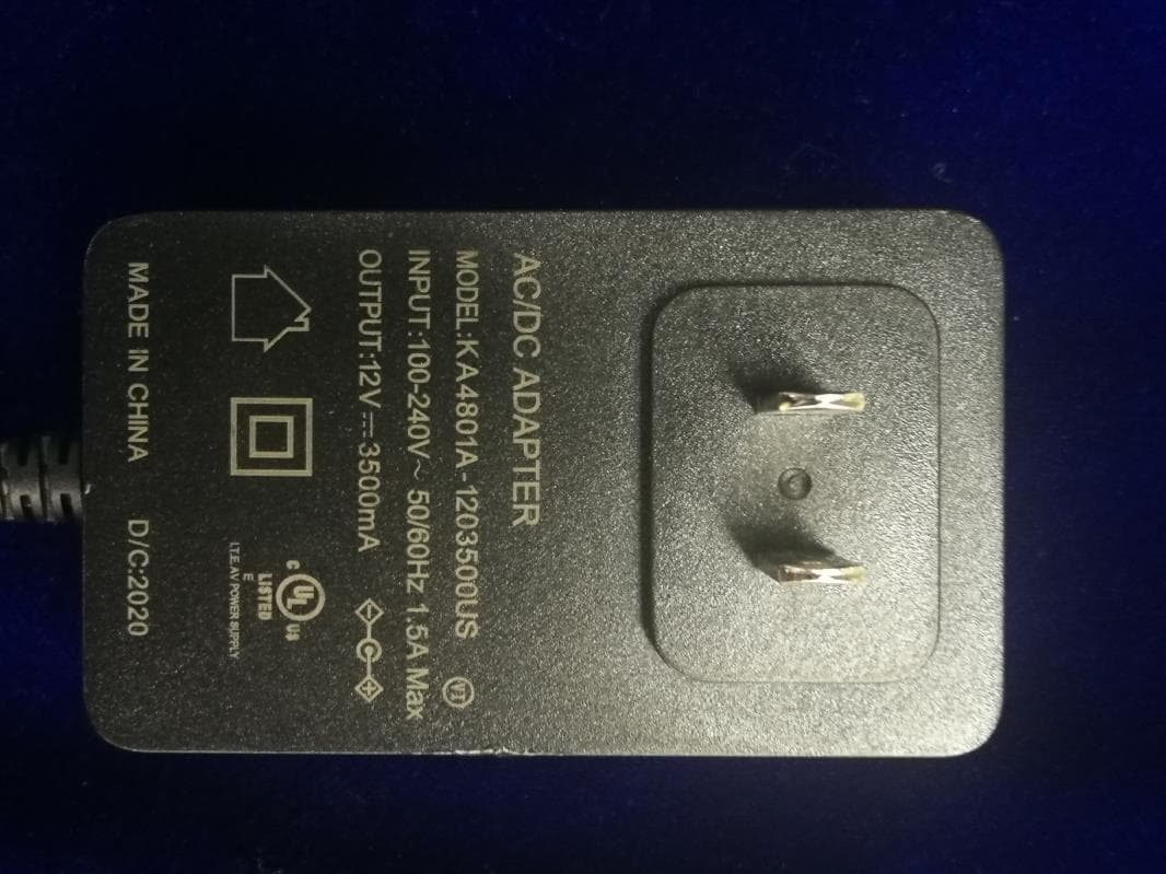
Click to zoom
Application Details
- Equipment Class
- DCD - Part 15 Low Power Transmitter Below 1705 kHz
- Date of Grant
- Sep 13, 2020
- Application Purpose
- Original Equipment
- Date of Application
- Sep 13, 2020
- Equipment Note
- MATCO TWIN LIGHT WORK LIGHT
- Frequency Range
- 0.11000000 - 0.20500000
- Company
- JS PRODUCTS INC
- Country
- United States
Documents & Files
Document Text
Text extracted from the exhibit documents filed with the FCC. Open a document above to read the original.
Users Manual
Mateo Tools I Stow, Ohio 44224 www.matcotools.com 2005069-08 TMATCO TOOLS WIN LIGHT WORK LIGHT WITH INDUCTION CHARGING PAD PLEASE READ CAREFULLY & FOLLOW DIRECTIONS BEFORE USE BEFORE INITIAL USE- CHARGE FULLY BEFORE USE CHARGING INSTRUCTIONS: 1. Lift rubber cover on back of the charging dock, insert 5.5mm plug into jack on charging dock, and insert wall adapter into AC power source. 2. To charge both modules: Place bottom light module onto charging dock with recessed charging contacts facing down. Place top light module onto the bottom light module with flashlight facing up. 3. To charge individual modules: Place either light module onto charging dock with recessed charging contacts facing down. 4. Charge indicator light on side of light module will turn RED when charging. Charge indicator light will turn GREEN when fully charged. Note: Modules should only be attached using magnetic force of built-in magnets. OPERATING INSTRUCTIONS: 1. Depress and release button to tum light on and toggle through lighting modes. 2. Top light module flashlight button modes: High/Low/Off. 3. Top light module work light button modes: White LED HighAVhite LED Low/Red LED On/Red LED Flasher/Off. 4. Bottom light module top button for White LED: High/Low/Off. 5. Bottom light module bottom button for UV LED: On/Off. 6. Depress button and hold for 3 seconds in any mode to turn off light. 7. Qi inductive charging compatible devices can be placed on induction charging pad to recharge. 8. Insert USB plug into front USB ports to charge/power USB devices. 9. Built-in magnets on base and sides of the hexagonal top and bottom module can be used to mount light modules to magnetic surfaces. 10. Carabineer belt clip can be used by pushing the clip over the narrow body portion of the light module and sliding the clip up until secure. REPLACEMENT COMPONEhTTS / ACCESSORIES: FSMWLTL-4 - Charging dock with induction charging pad (dock only) FSMWLTL-5 - AC wall charger adapter (3.5A) GENERAL GUIDELINES AND WARNINGS: • Improper handling of the device may result in fire, personal injury, or property damage. • Never charge device unattended. Do not charge on or near flammable material. Only charge using included wall adapter. • Modules should only be attached using magnetic force of built-in magnets. • If device begins to balloon, swell, or smoke, discontinue using or charging immediately and observe device in a safe place. • Do not short-circuit, crush, incinerate, or disassemble the device. • Do not use if device or charging cable are damaged. • Do not dispose of batteries in trash. Always recycle batteries according to national or local regulations. • The integrated battery should not be exposed to excessive heat such as sunshine, fire, etc. • For optimal battery life, device should be operated and stored between 40°F - 80°F MWLTL FSMWLTL-1 - Top light module FSMWLTL-2 - Bottom light module FSMWLTL-3 - Carabineer belt hook Mateo Tools I Stow, Ohio 44224 www.matcotools.com 2005069-08 WARNING: Cancer and Reproductive Harm. www.P65Warnings.ca.gov The Twin Light Work Light is backed by a 1 Year Warranty. This warranty covers manufacturer defects and workmanship. The warranty excludes misuse or abuse and normal wear and tear. Exclusion is not allowed in some states and may not apply. This warranty gives you specific legal rights, and you may have other rights, which vary from state to state. This device complies with Part 15 of the FCC Rules. Operation is subject to the following two conditions: (1) this device may not cause harmful interference. (2) this device must accept any interference received, including interference that may cause undesired operation. Changes or modifications not expressly approved by the party responsible for compliance could void the user's authority to operate the equipment. This equipment has been tested and found to comply with the limits for a Class B digital device, pursuant to part 15 of the FCC Rules. These limits are designed to provide reasonable protection against harmful interference in a residential installation. This equipment generates uses and can radiate radio frequency energy and, if not installed and used in accordance with the instructions, may cause harmful interference to radio communications. However, there is no guarantee that interference will not occur in a particular installation. If this equipment does cause harmful interference to radio or television reception, which can be determined by turning the equipment off and on, the user is encouraged to try to correct the interference by one or more of the following measures: —Reorient or relocate the receiving antenna. —Increase the separation between the equipment and receiver. —Connect the equipment into an outlet on a circuit different from that to which the receiver is connected. —Consult the dealer or an experienced radio/TV technician for help.
Cover Letter(s)
Declaration We, Name: JS Products, Inc. Address: 6445 Montessouri St Las Vegas NV 89113 United States declare that MWLTL, TL1007 are fully same except for the model name. Declared by: JS Products, Inc. Name: Rich Yang Signature: Date:2020-08-20
Cover Letter(s)
Product name: MATCO TWIN LIGHT WORK LIGHT Type/Model: MWLTL, TL1007 FCC ID 2AWIIMWLTL (1) Power transfer frequency is less than 1 MHz. Answer: The power transfer frequency is 110kHz – 205kHz (2) Output power from each primary coil is less than or equal to 15 watts. Answer: The max output power from each primary coil is 15 watts. (3) The transfer system includes only single primary and secondary coils. This includes charging systems that may have multiple primary coils and clients that are able to detect and allow coupling only between individual pairs of coils. Answer: The product has only single primary and secondary coils (4) Client device is placed directly in contact with the transmitter. Answer: The client device is placed directly in contact with the transmitter. (5) Mobile exposure conditions only (portable exposure conditions are not covered by this exclusion). Answer: Mobile exposure condition is used. (6) The aggregate H-field strengths at 15 cm surrounding the device and 20 cm above the top surface from all simultaneous transmitting coils are demonstrated to be less than 50% of the MPE limit. Answer: The H-field strengths at 15 cm surrounding the device and 20 cm above the top surface from all simultaneous transmitting coils is less than 50% of the MPE limit.
Cover Letter(s)
JS Products, Inc. Authority to Act as Agent Date: Aug 20, 2020 American Certification Body, Inc. 6731 Whittier Avenue Suite C110 McLean, VA 22101 To Whom It May Concern: _____Intertek Testing Service Shanghai______ is authorized to act on our behalf, until otherwise notified, for applications to American Certification Body, Inc. (ACB). We certify that we are not subject to denial of federal benefits, that includes FCC benefits, pursuant to Section 5301 of the Anti-Drug Abuse Act of 1988, 21 U.S.C. 862. Further, no party, as defined in 47 CFR 1.2002 (b), to the application is subject to denial of federal benefits, that includes FCC benefits. We also declare that the information provided to the FCC is true and correct to the best of our knowledge (47 CFR 2.911(d)) and we have been informed of the grantee responsibilities (47 CFR 2.909) with regard to certified equipment. Thank you, Agency Agreement Expiration Date: _____Dec 31, 2021 By: __________________________ _____ Rich Yang ____________ (Signature 1 ) (Print name) Title: ______ ____________________ On behalf of: __ JS Products, Inc.________________ (Company Name) Telephone: _____ ___________________ 1 - Must be signed by applicant contact given for applicant on the FCC site, or by the authorized agent if an appropriate authorized agent letter has been provided. Letters should be placed on appropriate letterhead. VP of Research and Development 702-212-1300
Cover Letter(s)
JS Products, Inc. Request for Confidentiality Date: Aug 20, 2020 Subject: Confidentiality Request for: __FCC ID: 2AWIIMWLTL Pursuant to FCC 47 CFR 0.457(d) and 0.459 and IC RSP-100, Section 9.4, the applicant requests that a part of the subject FCC application be held confidential. Type of Confidentiality Requested Exhibit ☐ Short Term ☒ Permanent Block Diagrams ☐ Short Term External Photos ☐ Short Term ☐ Permanent * 1 Internal Photos ☐ Short Term ☒ Permanent Operation Description/Theory of Operation ☐ Short Term ☐ Permanent Parts List & Placement/BOM ☐ Short Term ☐ Permanent Tune-Up Procedure ☐ Short Term ☒ Permanent Schematics ☐ Short Term Test Setup Photos ☐ Short Term ☐ Permanent * 3 User’s Manual ______ JS Products, Inc. has spent substantial effort in developing this product and it is one of the first of its kind in industry. Having the subject information easily available to "competition" would negate the advantage they have achieved by developing this product. Not protecting the details of the design will result in financial hardship. Permanent Confidentiality: The applicant requests the exhibits listed above as permanently confidential be permanently withheld from public review due to materials that contain trade secrets and proprietary information not customarily released to the public. Short-Term Confidentiality: The applicant requests the exhibits selected above as short term confidential be withheld from public view for a period of ___(specify number of days not to exceed 180) 2 ___ days from the date of the Grant of Equipment Authorization and prior to marketing. This is to avoid premature release of sensitive information prior to marketing or release of the product to the public. Applicant is also aware that they are responsible to notify ACB in the event information regarding the product or the product is made available to the public before the requested period has expired. ACB will then release the documents listed above for public disclosure pursuant to FCC Public Notice DA 04-1705. NOTE for Industry Canada Applications: IC currently only distinguishes Permanent Confidentiality exhibits as shown above. Short Term confidentiality is not considered applicable to IC applications. Sincerely, By: __________________________ ______ Rich Yang __________________ (Signature/Title 3 ) (Print name) 1 - The asterisked items (*) require further information to be provided to ACB before permanent confidentiality will be extended to these exhibits. Please refer to FCC KDB 726920 and the specific Document link for D01 found at: https://apps.fcc.gov/oetcf/kdb/forms/FTSSearchResultPage.cfm?switch=P&id=41731 and review section II, 3) regarding specific information that must accompany these requests. 2 - Please refer to http://acbcert.com/documents/misc-docs/Memo-Short-Term-Vs-Standard-Confidentiality.pdf for complete details. 3 - Must be signed by applicant contact given for applicant on the FCC site, or by the authorized agent if an appropriate authorized agent letter has been provided. Letters should be placed on appropriate letterhead. VP of Research and Development
External Photos
FCC ID: 2AWIIMWLTL Page 1 of 6 External Picture FCC ID: 2AWIIMWLTL Page 2 of 6 FCC ID: 2AWIIMWLTL Page 3 of 6 FCC ID: 2AWIIMWLTL Page 4 of 6 FCC ID: 2AWIIMWLTL Page 5 of 6 FCC ID: 2AWIIMWLTL Page 6 of 6
ID Label/Location Info
Label location label
Internal Photos
FCC ID: 2AWIIMWLTL Page 1 of 12 Internal Picture FCC ID: 2AWIIMWLTL Page 2 of 12 FCC ID: 2AWIIMWLTL Page 3 of 12 FCC ID: 2AWIIMWLTL Page 4 of 12 FCC ID: 2AWIIMWLTL Page 5 of 12 FCC ID: 2AWIIMWLTL Page 6 of 12 FCC ID: 2AWIIMWLTL Page 7 of 12 FCC ID: 2AWIIMWLTL Page 8 of 12 FCC ID: 2AWIIMWLTL Page 9 of 12 FCC ID: 2AWIIMWLTL Page 10 of 12 FCC ID: 2AWIIMWLTL Page 11 of 12 FCC ID: 2AWIIMWLTL Page 12 of 12
RF Exposure Info
JS Products, Inc. MPE ASSESSMENT REPORT Report Type: FCC MPE assessment report Model: MWLTL, TL1007 REPORT NUMBER: 200602724SHA-002 ISSUE DATE: Sep 9, 2020 DOCUMENT CONTROL NUMBER: TTRFFCCMPE-02_V1 © 2018 Intertek Intertek Testing Services Shanghai Building No.86, 1198 Qinzhou Road (North) Caohejing Development Zone Shanghai 200233, China Telephone: 86 21 6127 8200 www.intertek.com TEST REPORT This report is for the exclusive use of Intertek's Client and is provided pursuant to the agreement between Intertek and its Client. Intertek's responsibility and liability are limited to the terms and conditions of the agreement. Intertek assumes no liability to any party, other than to the Client in accordance with the agreement, for any loss, expense or damage occasioned by the use of this report. Only the Client is authorized to permit copying or distribution of this report and then only in its entirety. Any use of the Intertek name or one of its marks for the sale or advertisement of the tested material, product or service must first be approved in writing by Intertek. The observations and test results in this report are relevant only to the sample tested. This report by itself does not imply that the material, product, or service is or has ever been under an Intertek certification program. TTRFFCCMPE-02_V1© 2018 Intertek Page 2 of 10 Report no.: 200602724SHA-002 Applicant: JS Products, Inc. 6445 Montessouri St Las Vegas NV 89113 United States Manufacturer: JS Products, Inc. 6445 Montessouri St Las Vegas NV 89113 United States Manufacturing site: Ningbo Taller Electrical Appliance Co LTD Gongji Road#1, Simen Industrial Zone, Yuyao, Zhejiang China 315470 FCC ID: 2AWIIMWLTL SUMMARY: The equipment complies with the requirements according to the following standard(s) or Specification: FCC PART 1 SECTION 1.1310 PREPARED BY: REVIEWED BY: Project Engineer Teddy Yin Reviewer Daniel Zhao Report No.: 200602724SHA-002 TEST REPORT TTRFFCCMPE-01_V1© 2018 Intertek Page 3 of 10 Revision History Report No. Version Description Issued Date 200602724SHA-002 Rev. 01 Initial issue of report Sep 9, 2020 Report No.: 200602724SHA-002 TEST REPORT TTRFFCCMPE-01_V1© 2018 Intertek Page 4 of 10 Measurement result summary TEST ITEM FCC REFERANCE TEST RESULT NOTE RF Exposure 1.1310 Pass - Notes: 1: NA =Not Applicable 2. Determination of the test conclusion is based on IEC Guide 115 in consideration of measurement uncertainty. 3: Additions, Deviations and Exclusions from Standards: None. Report No.: 200602724SHA-002 TEST REPORT TTRFFCCMPE-01_V1© 2018 Intertek Page 5 of 10 1 GENERAL INFORMATION 1.1 Description of Equipment Under Test (EUT) Product name: MATCO TWIN LIGHT WORK LIGHT Type/Model: MWLTL, TL1007 Description of EUT: EUT is a work light with wireless charge function. Both models are same except for the model name. Rating: Charger: Input: DC 12V, 3.5A Wireless charge output: DC 5V/1A, DC 9V/1.1A, DC 12/1.25A USB output: DC 5V, 2A*2(total 4A) Light: DC 3.7V, 2000mAh*2 Adaptor: Input: 100-240V~, 50/60Hz, 1.5A Max Output: DC 12V, 3.5A Category of EUT: Class B EUT type: Table top Floor standing Software Version: / Hardware Version: / Sample received date: Jul 5, 2020 Date of test: Jul 5~Aug 14, 2020 1.2 Technical Specification Frequency Range: 110kHz – 205kHz Report No.: 200602724SHA-002 TEST REPORT TTRFFCCMPE-01_V1© 2018 Intertek Page 6 of 10 1.3 Description of Test Facility Name: Intertek Testing Services Shanghai Address: Building 86, No. 1198 Qinzhou Road(North), Shanghai 200233, P.R. China Telephone: 86 21 61278200 Telefax: 86 21 54262353 The test facility is recognized, certified, or accredited by these organizations: CNAS Accreditation Lab Registration No. CNAS L0139 FCC Accredited Lab Designation Number: CN1175 IC Registration Lab CAB identifier.: CN0051 VCCI Registration Lab Registration No.: R-14243, G-10845, C-14723, T-12252 A2LA Accreditation Lab Certificate Number: 3309.02 Report No.: 200602724SHA-002 TEST REPORT TTRFFCCMPE-01_V1© 2018 Intertek Page 7 of 10 2 TEST SPECIFICATIONS 2.1 Standards or specification FCC PART 1 SECTION 1.1310 KDB 680106 D01 RF Exposure Wireless Charging App v03 2.2 Mode of operation during the test Within this test report, EUT was tested under all modes and tested under its rating voltage and frequency. Other voltage and frequency are specified if used. The worst data was listed in the report. 2.3 Test peripherals list Item No. Name Band and Model Description 1 Wireless load / 100% power level 2 Wireless load / 50% power level 3 Wireless load / 0% power level 4 Adaptor KA4801A-1203500US Input: 100-240V~, 50/60Hz, 1.5A Max Output: DC 12V, 3.5A 2.4 Record of climatic conditions Test Item Temperature (°C) Relative Humidity (%) Pressure (kPa) RF Exposure 25C 55% RH 101 Report No.: 200602724SHA-002 TEST REPORT TTRFFCCMPE-01_V1© 2018 Intertek Page 8 of 10 2.5 Instrument list Used Equipment Manufacturer Type Internal no. Due date Exposure Level Tester Narda NBM-550 EC 6113 2020-11-20 Field sensor & Field meter Narda EF 0391 EC 6113 2020-12-26 Report No.: 200602724SHA-002 TEST REPORT TTRFFCCMPE-01_V1© 2018 Intertek Page 9 of 10 3 RF Exposure Assessment Test result: Pass 3.1 Assessment Limit 3.2 Assessment Configuration Report No.: 200602724SHA-002 TEST REPORT TTRFFCCMPE-01_V1© 2018 Intertek Page 10 of 10 3.3 Assessment Results Test result of Magnetic Field Strength: Test Position Test distance (cm) Test result (A/m) Limit (A/m) Result (Pass/Fail) A: Right 15 0.0022 1.63 *0.5 Pass B: Left 15 0.0018 1.63 *0.5 Pass C: Front 15 0.0026 1.63 *0.5 Pass D: Back 15 0.0011 1.63 *0.5 Pass E: Top 20 0.0059 1.63 *0.5 Pass Test result of Electric Field Strength: Test Position Test distance (cm) Test result (V/m) Limit (V/m) Result (Pass/Fail) A: Right 15 1.02 614 *0.5 Pass B: Left 15 0.82 614 *0.5 Pass C: Front 15 1.28 614 *0.5 Pass D: Back 15 0.42 614 *0.5 Pass E: Top 20 2.29 614 *0.5 Pass ******************************************* END ************************************
Test Report
JS Products, Inc. RF TEST REPORT Report Type: FCC Part 15C RF report Model: MWLTL, TL1007 REPORT NUMBER: 200602724SHA-001 ISSUE DATE: Sep 9, 2020 DOCUMENT CONTROL NUMBER: TTRFFCCPART15C_V1 © 2018 Intertek Intertek Testing Services Shanghai Building No.86, 1198 Qinzhou Road (North) Caohejing Development Zone Shanghai 200233, China Telephone: 86 21 6127 8200 www.intertek.com TEST REPORT This report is for the exclusive use of Intertek's Client and is provided pursuant to the agreement between Intertek and its Client. Intertek's responsibility and liability are limited to the terms and conditions of the agreement. Intertek assumes no liability to any party, other than to the Client in accordance with the agreement, for any loss, expense or damage occasioned by the use of this report. Only the Client is authorized to permit copying or distribution of this report and then only in its entirety. Any use of the Intertek name or one of its marks for the sale or advertisement of the tested material, product or service must first be approved in writing by Intertek. The observations and test results in this report are relevant only to the sample tested. This report by itself does not imply that the material, product, or service is or has ever been under an Intertek certification program. TTRFFCCPART15C_V1 © 2018 Intertek Page 2 of 19 Report no.: 200602724SHA-001 Applicant: JS Products, Inc. 6445 Montessouri St Las Vegas NV 89113 United States Manufacturer: JS Products, Inc. 6445 Montessouri St Las Vegas NV 89113 United States Manufacturing site: Ningbo Taller Electrical Appliance Co LTD Gongji Road#1, Simen Industrial Zone, Yuyao, Zhejiang China 315470 FCC ID: 2AWIIMWLTL SUMMARY: The equipment complies with the requirements according to the following standard(s) or Specification: 47CFR Part 15 (2019): Radio Frequency Devices (Subpart C) ANSI C63.10 (2013): American National Standard of Procedures for Compliance Testing of Unlicensed Wireless Devices PREPARED BY: REVIEWED BY: Project Engineer Teddy Yin Reviewer Daniel Zhao Report No.: 200602724SHA-001 TEST REPORT TTRFFCCPART15C_V1 © 2018 Intertek Page 3 of 19 Content REVISION HISTORY................................................................................................................................................ 4 MEASUREMENT RESULT SUMMARY ..................................................................................................................... 5 1 GENERAL INFORMATION ............................................................................................................................. 6 1.1 DESCRIPTION OF EQUIPMENT UNDER TEST (EUT) ..................................................................................................... 6 1.2 TECHNICAL SPECIFICATION .................................................................................................................................... 6 1.3 DESCRIPTION OF TEST FACILITY .............................................................................................................................. 7 2 TEST SPECIFICATIONS ................................................................................................................................... 8 2.1 STANDARDS OR SPECIFICATION ............................................................................................................................... 8 2.2 MODE OF OPERATION DURING THE TEST ................................................................................................................... 8 2.3 TEST SOFTWARE LIST ............................................................................................................................................ 8 2.4 TEST PERIPHERALS LIST ......................................................................................................................................... 8 2.5 TEST ENVIRONMENT CONDITION: ............................................................................................................................ 8 2.6 INSTRUMENT LIST ................................................................................................................................................ 9 2.7 MEASUREMENT UNCERTAINTY ............................................................................................................................. 10 3 RADIATED EMISSIONS ............................................................................................................................... 11 3.1 LIMIT .............................................................................................................................................................. 11 3.2 MEASUREMENT PROCEDURE ............................................................................................................................... 11 3.3 TEST CONFIGURATION ........................................................................................................................................ 12 3.4 TEST RESULTS OF RADIATED EMISSIONS ................................................................................................................. 14 4 CONDUCTED EMISSIONS ........................................................................................................................... 16 4.1 LIMIT .............................................................................................................................................................. 16 4.2 TEST CONFIGURATION ........................................................................................................................................ 16 4.3 MEASUREMENT PROCEDURE ............................................................................................................................... 17 4.4 TEST RESULTS OF CONDUCTED EMISSIONS .............................................................................................................. 18 Report No.: 200602724SHA-001 TEST REPORT…
Text truncated - open the document above for the full version.
Test Setup Photos
FCC ID: 2AWIIMWLTL Page 1 of 4 Test Setup FCC ID: 2AWIIMWLTL Page 2 of 4 1. Radiated Emission 30MHz- 1GHz Below 30MHz FCC ID: 2AWIIMWLTL Page 3 of 4 2. Conducted Emission FCC ID: 2AWIIMWLTL Page 4 of 4 3. RF Exposure for FCC
Contact Information
Applicant
Rich Yang(VP of Research and Development)
Technical Contact
Intertek Testing Services ShanghaiTeddy Yin
[email protected]86-21-61215198
Building No.86 · Shanghai · China
Non-Technical Contact
Intertek Testing Services ShanghaiTeddy Yin
[email protected]86-21-61215198
Test Firm
Intertek Testing Services Limited, ShanghaiLeah Xu
[email protected]+86 21 61278200
Technical Specifications
| # | Rule Parts | Frequency Range | Power Output |
|---|---|---|---|
| 1 | 15C | 0.11 MHz - 0.205 MHz | - |