2AWK8IN6000INTRANAV NODE
IntraNav GmbH
Click to zoom
Application Details
- Equipment Class
- UWB - Ultra Wideband Transmitter
- Date of Grant
- Oct 04, 2022
- Application Purpose
- Original Equipment
- Date of Application
- Sep 15, 2022
- Equipment Note
- INTRANAV NODE
- Frequency Range
- 6234.90000000 - 6813.80000000
- Company
- IntraNav GmbH
- Country
- Germany
Documents & Files
Document Text
Text extracted from the exhibit documents filed with the FCC. Open a document above to read the original.
Users Manual
V1.1 Quick start guide for the INTRANAV RTLS NODE (IN6000) INTRANAV RTLS NODE with Wi-Fi (IN6200) ENGLISH Quick Guide INTRANAV NODE 1 INTRANAV RTLS NODE (IN6200) - Quick Guide IntraNav GmbH Frankfurter Str. 27 65760 Eschborn, Germany Email: [email protected]: www. IntraNav.com Registered office of the company: Frankfurt am Main (HRB 92924), responsible for the content: Ersan Günes Management Andreas Radix Ersan Günes Gonzalo Ibarra © Copyright 2021, IntraNav GmbH This work is protected by copyright. Its use outside the narrow limits of copyright law is not permitted without the consent of the publisher and is punishable by law. This applies in particular to reproduction, translation, microfilming and storage and processing in electronic systems. All rights reserved. Revisions 12.12.2021 Ersan Günes [EG] Initial 2 Content 3 Content 1 Legal information ........................................................................... 4 2 Overview ........................................................................................ 7 General ................................................................................................ 7 Scope of delivery and accessories ...................................................... 7 Power supply ....................................................................................... 7 Areas of application ............................................................................ 7 Product dimension .............................................................................. 8 3 Installation, commissioning, maintenance and safety ................... 9 Assembly and operation ................................................................... 9 Connecting the cables and lines ....................................................... 10 Supply voltage ................................................... Ethernet ............................................................................................ 10 Operating the device ......................................................................... 11 Cleaning and maintenance ............................................................... 12 4 Technical data .............................................................................. 13 5Approvals .............................................................................................. 14 EU Declaration of Conformity ........................................................... 14 RoHS .................................................................................................. 14 RED (Radio Equipment Directive) ..................................................... 15 6 Recycling and waste disposal ........................................................ 18 7 Troubleshooting ........................................................................... 19 ................... .............10 V1.0 Legal notice 4 IntraNav GmbHFrankfurter Str. 2765760 Eschborn [email protected] Commerzbank FrankfurtIBAN DE91 5004 0000 0571 9141 00BIC COBADEFFXXX Commercial RegisterLocal Court Frankfurt a. M. HRB 92924 1 Legal notice Warnings These instructions contain information that you must observe for your personal safety and to avoid damage to property. The instructions for your personal safety are highlighted by a warning triangle. Information on damage to property alone is not indicated by a warning triangle. Depending on the hazard level, the warnings are shown in decreasing order as follows. DANGER: means that death or serious injury will occur if the appropriate precautions are not taken. WARNING: means that death or serious injury may occur if the appropriate precautions are not taken. CAUTION: indicates that minor personal injury may occur if proper precautions are not taken. Legal notice .0 5 IntraNav GmbHFrankfurter Str. 2765760 Eschborn [email protected] Commerzbank FrankfurtIBAN DE91 5004 0000 0571 9141 00BIC COBADEFFXXX Commercial RegisterLocal Court Frankfurt a. M. HRB 92924 CAUTION: means that property damage may occur if the appropriate precautions are not taken. If several hazard levels occur, the warning for the highest level is always used. If the warning triangle is used in a warning against personal injury, then a warning against property damage can also be added to the same warning. Qualified personnel The product/system associated with this documentation may only be handled by personnel qualified for the respective task and in compliance with the associated documentation for the respective task, in particular the safety and warning instructions contained therein. Due to their training and experience, qualified personnel are capable of recognizing risks and avoiding possible hazards when handling these products/systems. Intended use of INTRANAV products Consider the following: WARNING: INTRANAV products may only be used for the applications specified in the catalogue and in the associated technical documentation. If third-party products and components are used, they must be recommended or approved by INTRANAV. Faultless and safe operation of the products requires proper transport, storage, assembly, installation, commissioning, operation and maintenance. The permissible ambient conditions must be observed. The instructions in the relevant documentation must be observed. Brands All designations marked with ® are registered trademarks of IntraNav GmbH. The other designations in this document may be trademarks whose V1.0 Legal notice 6 IntraNav GmbHFrankfurter Str. 2765760 Eschborn [email protected] Commerzbank FrankfurtIBAN DE91 5004 0000 0571 9141 00BIC COBADEFFXXX Commercial RegisterLocal Court Frankfurt a. M. HRB 92924 use by third parties for their own purposes may infringe the rights of the owner. Disclaimer We have checked the contents of this publication for conformity with the hardware and software described. Nevertheless, deviations cannot be ruled out, so that we cannot guarant…
Text truncated - open the document above for the full version.
Cover Letter(s)
IntraNav GmbH Address: Frankfurter Str. 27, 65760 Eschborn, Germany Tel.:+49 6196-20471 81 Fax: +49 6196-20471 89 E-mail: [email protected] QA-FR-170-B FCC Authorization Date: 2022-05-20 FEDERAL COMMUNICATIONS COMMISSIONS Authorization and Evaluation Division 7435 Oakland Mills Road Columbia, MD 21046 Subject: Agent Authorization To whom it may concern: We, IntraNav GmbH hereby authorizes Shenzhen Accurate Technology Co., Ltd. to act on its behalf in all matters relating to application for Equipment authorization, including the signing of all documents relating to these matters. All acts carried out by Shenzhen Accurate Technology Co., Ltd.on our behalf shall have the same effect as our own action. We, the undersigned, hereby certify that we are not subject to a denial of federal benefits, that includes FCC benefits, pursuant to Section 5301 of the Anti-Drug Abuse Act of 1988, 21 U.S.C. 862. This authorization is valid until further written notice from the applicant. Sincerely Yours, Signature: Manager Ersan Gunes
Cover Letter(s)
IntraNav GmbH Address: Frankfurter Str. 27, 65760 Eschborn, Germany Tel.:+49 6196-20471 81 Fax: +49 6196-20471 89 E-mail: [email protected] FCC Confidential Authorization Date: 2022-05-20 FEDERAL COMMUNICATIONS COMMISSIONS Authorization and Evaluation Division 7435 Oakland Mills Road Columbia, MD 21046 Subject: Confidentiality Request regarding application for certification of FCC ID: 2AWK8IN6000 In accordance with Sections 0.457 and 0.459 of the Commission’s Rules, IntraNav GmbH, hereby requests long-term confidential treatment of information accompanying this application as outlined below: Block Diagram Schematics Operation Description The above materials contain proprietary and confidential information not customarily released to the public. The public disclosure of these materials provides unjustified benefits to its competitors in the market. Sincerely Yours, Signature Manager Ersan Gunes
External Photos
Shenzhen Accurate Technology Co., Ltd. Project No.: SZNS220413-14011E-RF External Photos Page 1 of 3 External Photos Shenzhen Accurate Technology Co., Ltd. Project No.: SZNS220413-14011E-RF External Photos Page 2 of 3 Shenzhen Accurate Technology Co., Ltd. Project No.: SZNS220413-14011E-RF External Photos Page 3 of 3
ID Label/Location Info
Shenzhen Accurate Technology Co., Ltd. Project No.: SZNS220413-14011E-RF LABEL AND LOCATION Page 1 of 1 FCC ID Label FCC ID Label Location Information The label shown shall be permanently affixed at a conspicuous location on the device and be readily visible to the user at the time purchase (Labeling requirements per 2.925)
Internal Photos
Shenzhen Accurate Technology Co., Ltd. Project No.: SZNS220413-14011E-RF Internal Photos Page 1 of 3 Internal photos Shenzhen Accurate Technology Co., Ltd. Project No.: SZNS220413-14011E-RF Internal Photos Page 2 of 3 Shenzhen Accurate Technology Co., Ltd. Project No.: SZNS220413-14011E-RF Internal Photos Page 3 of 3
RF Exposure Info
Shenzhen Accurate Technology Co., Ltd. Report No.: SZNS220413-14011E-RF-00 Version 61: 2021-11-09 Page 9 of 32 FCC-UWB FCC§1.1310&§2.1093- RF EXPOSURE Applicable Standard RF Exposure for devices that operate above 6GHz (§1.1310) According to subpart 2.1093(d): Portable devices that transmit at frequencies above 6GHz shall be evaluated in terms of the MPE limits specified in table 1 to 47 CFR 1.1310. A minimum separation distance applicable to the operating configurations and exposure conditions of the device shall be used for the evaluation. Measurements and calculations to demonstrate compliance with MPE field strength or power density limits for device operating above 6GHz should be made at a minimum distance of 0.5cm from the radiating source. Limits for General Population/Uncontrolled Exposure Limits for General Population/Uncontrolled Exposure Frequency Range (MHz) Electric Field Strength (V/m) Magnetic Field Strength (A/m) Power Density (mW/cm 2 ) Averaging Time (Minutes) 0.3-1.34 614 1.63 *(100) 30 1.34-30 824/f 2.19/f *(180/f 2 ) 30 30-300 27.5 0.073 0.2 30 300-1500 / / f/1500 30 1500-100,000 / / 1.0 30 f = frequency in MHz * = Plane-wave equivalent power density Result Calculated Formulary: Predication of MPE limit at a given distance S = 2 4R PG π S = power density (in appropriate units, e.g. mW/cm 2 ) P = power input to the antenna (in appropriate units, e.g., mW). G = power gain of the antenna in the direction of interest relative to an isotropic radiator, the power gain factor, is normally numeric gain. R = distance to the center of radiation of the antenna (appropriate units, e.g., cm) Frequency (MHz) Tune up EIRP Evaluation Distance (cm) Power Density (mW/cm 2 ) MPE Limit (mW/cm 2 ) (dBm) (mW) 6489.6 -6.0 0.25 20 0.00005 1 Note: To maintain compliance with the FCC’s RF exposure guidelines, place the equipment at least 20cm from nearby persons. Result: Compliance
Test Report
Note: This report may c ★ ontain data that are not covered by the A2LA accreditation and are marked with an asterisk “ ”. Shenzhen Accurate Technology Co., Ltd. is not responsible for the authenticity of any test data provided by the applicant. Data included from the applicant that may affect test results are marked with an asterisk ’*’. Customer model name, addresses, names, trademarks etc. are not considered data. This report cannot be reproduced except in full, without prior written approval of the Company. Unless otherwise stated the results shown in this test report refer only to the sample(s) tested. This report is valid only with a valid digital signature. The digital signature may be available only under the Adobe software above version 7.0. Shenzhen Accurate Technology Co., Ltd. 1/F., Building A, Changyuan New Material Port, Science & Industry Park, Nanshan District, Shenzhen, Guangdong, P.R. China Tel: +86 755-26503290 Fax: +86 755-26503396 Web: www.atc-lab.com Version61: 2021-11-09 Page 1 of 32 FCC-UWB TESTREPORT Applicant Name : IntraNav GmbH Address : Frankfurter Str. 27, Eschborn, Germany 65760 Report Number: SZNS220413-14011E-RF-00 FCC ID: 2AWK8IN6000 Test Standard (s) FCC PART 15F Sample Description Product Type: INTRANAV NODE Model No.: IN6000/10111013 Multiple Model(s) No.: N/A Trade Mark: Date Received: 2022/04/13 Report Date: 2022/05/26 Test Result: Pass* * In the configuration tested, the EUT complied with the standards above. Prepared and Checked By: Approved By: Ting Lü Candy Li EMC Engineer EMC Engineer Shenzhen Accurate Technology Co., Ltd. Report No.: SZNS220413-14011E-RF-00 Version 61: 2021-11-09 Page 2 of 32 FCC-UWB TABLE OF CONTENTS GENERAL INFORMATION ....................................................................................................................................... 3 PRODUCT DESCRIPTION FOR EQUIPMENT UNDER TEST (EUT) ..................................................................................... 3 OBJECTIVE ................................................................................................................................................................... 3 TEST METHODOLOGY .................................................................................................................................................. 3 MEASUREMENT UNCERTAINTY .................................................................................................................................... 3 TEST FACILITY ............................................................................................................................................................. 4 SYSTEM TEST CONFIGURATION .......................................................................................................................... 5 DESCRIPTION OF TEST CONFIGURATION ...................................................................................................................... 5 EQUIPMENT MODIFICATIONS ....................................................................................................................................... 5 EUT EXERCISE SOFTWARE .......................................................................................................................................... 5 SUMMARY OF TEST RESULTS ............................................................................................................................... 7 TEST EQUIPMENT LIST ........................................................................................................................................... 8 FCC§1.1310&§2.1093- RF EXPOSURE ........................................................................................................................ 9 APPLICABLE STANDARD .............................................................................................................................................. 9 RESULT ........................................................................................................................................................................ 9 FCC §15.517 (A) - GENERAL REQUIREMENT .................................................................................................... 10 APPLICABLE STANDARD ............................................................................................................................................ 10 RESULT ...................................................................................................................................................................... 10 FCC §15.203& §15.517 (A)(3) - ANTENNA REQUIREMENT .............................................................................. 11 FCC §15.207 (A) -AC POWER LINE CONDUCTED EMISSIONS ...................................................................... 12 APPLICABLE STANDARD ............................................................................................................................................ 12 EUT SETUP ................................................................................................................................................................ 12 EMI TEST RECEIVER SETUP ....................................................................................................................................... 12 TEST PROCEDURE ...................................................................................................................................................... 13 TEST RESULTS SUMMARY .......................................................................................................................................... 13 TRANSD FACTOR & MARGIN CALCULATION.............................................................................................................. 13 TEST DATA ................................................................................................................................................................ 1…
Text truncated - open the document above for the full version.
Test Report
Every effort has been made to ensure that the information contained in this document is correct. However the information is provisional and subject to change. All information is provided strictly for informational purposes and is proprietary to DecaWave. DecaWave reserves the right to withdraw, modify, or replace the specification at any time, without notice. No obligation is made by DecaWave regarding the level, scope, or timing of DecaWave's implementation of the functions or features discussed in this specification. The specification is “as is” and DecaWave makes no warranty and disclaims all warranties expressed or implied. DecaWave accepts no liability whether statutory related or implied for any inaccuracy, omission, incompleteness or error of any kind. DecaWave accepts no liability for direct, indirect, consequential or incidental damages or incurred costs relating to any aspect of this information or its use. This information is © DecaWave and may not be copied, reproduced, or issued to any third party except to those with a need-to-know for the purpose noted above. All Rights Reserved. © 2015 DecaWave Ltd. PRODUCT INFORMATION: WB002 Overview of WB002, Ultra-wideband Omni-directional Planar Antenna • Specifically designed for operation with DW1000 based products • Good Omni-directional gain • Maximum gain at 4 GHz ~ 2.2 dBi • Maximum gain at 6.5 GH • Covers full DW1000 operational band (3-8 GHz) • Minimal group delay variation Design Data is free to download from decaWave 1 1 Subject to a non-exclusive licence agreement Key Benefits • Omni-directional • Low/zero cost implementation • Uses low cost FR4 PCB • Can be integrated into existing PCB • Proven design with DW1000 Target Applications • DW1000 based infrastructure (anchors) • DW1000 based tags (moderate size) z ~3.7dBi Every effort has been made to ensure that the information contained in this document is correct. However the information is provisional and subject to change. All information is provided strictly for informational purposes and is proprietary to DecaWave. DecaWave reserves the right to withdraw, modify, or replace the specification at any time, without notice. No obligation is made by DecaWave regarding the level, scope, or timing of DecaWave's implementation of the functions or features discussed in this specification. The specification is “as is” and DecaWave makes no warranty and disclaims all warranties expressed or implied. DecaWave accepts no liability whether statutory related or implied for any inaccuracy, omission, incompleteness or error of any kind. DecaWave accepts no liability for direct, indirect, consequential or incidental damages or incurred costs relating to any aspect of this information or its use. This information is © DecaWave and may not be copied, reproduced, or issued to any third party except to those with a need-to-know for the purpose noted above. All Rights Reserved. © 2015 DecaWave Ltd. PRODUCT INFORMATION: WB002
Test Report
IntraNav GmbH Frankfurter Str.27,65760 Eschborn,Germany Tel: +49 6196-20471 81 Fax: +49 6196-20471 89 Email: [email protected] Date: 2022-05-20 FEDERAL COMMUNICATIONS COMMISSIONS Authorization and Evaluation Division 7435 Oakland Mills Road Columbia, MD 21046 Subject: Compliant to FCC § 15.521 technical requirements for FCC ID: 2AWK8IN6000 (a) UWB devices may not be employed for the operation of toys. Operation onboard an aircraft, a ship or a satellite is prohibited. Reply: Compliant.The final device should not use for toys and device operation onboard an aircraft, a ship or a satellite,only for indoor use. (b) Manufacturers and users are reminded of the provisions of § 15.203 and 15.204. Reply: Compliant, use an antenna permanently attached to the device. Antenna cannot be modifications. (c) Emissions from digital circuitry used to enable the operation of the UWB transmitter shall comply with the limits in § 15.209, rather than the limits specified in this subpart, provided it can be clearly demonstrated that those emissions from the UWB device are due solely to emissions from digital circuitry contained within the transmitter and that the emissions are not intended to be radiated from the transmitter's antenna. Emissions from associated digital devices, as defined in § 15.3(k), e.g., emissions from digital circuitry used to control additional functions or capabilities other than the UWB transmission, are subject to the limits contained in Subpart B of this part. Reply: All radiation spurious emissions are compliant to FCC § 15.209 & 15.517. (d) Within the tables in §§ 15.509, 15.511, 15.513, 15.515, 15.517, and 15.519, the tighter emission limit applies at the band edges. Radiated emission levels at and below 960 MHz are based on measurements employing a CISPR quasi-peak detector. Radiated emission levels above 960 MHz are based on RMS average measurements over a 1 MHz resolution bandwidth. The RMS average measurement is based on the use of a spectrum analyzer with a resolution bandwidth of 1 MHz, an RMS detector, and a 1 millisecond or less averaging time. Unless otherwise stated, if pulse gating is employed where the transmitter is quiescent for intervals that are long compared to the nominal pulse repetition interval, measurements shall be made with the pulse train gated on. Alternative measurement procedures may be considered by the Commission. Reply: According to testing requirements, all radiation spurious emissions are compliant to UWB limits for FCC 15.517, including for the tighter emission limit applies at the band edges. (e) The frequency at which the highest radiated emission occurs, f M , must be contained within the UWB bandwidth. Reply: Compliant. The f M is contained within the UWB bandwidth, such as 10dB bandwidth. (f) Imaging systems may be employed only for the type of information exchange described in their specific definitions contained in § 15.503. The detection of tags or the transfer or data or voice information is not permitted under the standards for imaging systems. Reply: The product is not used for imaging system. (g) When a peak measurement is required, it is acceptable to use a resolution bandwidth other than the 50 MHz specified in this subpart. This resolution bandwidth shall not be lower than 1 MHz or greater than 50 MHz, and the measurement shall be centered on the frequency at which the highest radiated emission occurs, f M. If a resolution bandwidth other than 50 MHz is employed, the peak EIRP limit shall be 20 log (RBW/50) dBm where RBW is the resolution bandwidth in megahertz that is employed. This may be converted to a peak field strength level at 3 meters using E(dBuV/m) = P(dBm EIRP) + 95.2. If RBW is greater than 3 MHz, the application for certification filed with the Commission must contain a detailed description of the test procedure, calibration of the test setup, and the instrumentation employed in the testing. Reply: Compliant. Testing Peak as the requirements for the test procedure, calibration of the test setup, and the instrumentation employed. (h) The highest frequency employed in § 15.33 to determine the frequency range over which radiated measurements are made shall be based on the center frequency, fc, unless a higher frequency is generated within the UWB device. For measuring emission levels, the spectrum shall be investigated from the lowest frequency generated in the UWB transmitter, without going below 9 kHz, up to the frequency range shown in § 15.33(a) or up to fc + 3/(pulse width in seconds), whichever is higher. There is no requirement to measure emissions beyond 40 GHz provided fc is less than 10 GHz; beyond 100 GHz if fc is at or above 10 GHz and below 30 GHz; or beyond 200 GHz if fc is at or above 30 GHz. Reply: Compliant. Testing range compliant to this requirement for this product. And all radiation spurious emissions are compliant to UWB limits for FCC 15.517. (i) The prohibition in § 2.201(f) and 15.5(d) of this chapter against Class B (damped wave) emissions does not apply to UWB devices operating under this subpart. Reply: T his product will not produce Class B emissions (damped wave) (j) Responsible parties are reminded of the other standards and requirements cross referenced in § 15.505, such as a limit on emissions conducted onto the AC power lines. Reply: Compliant. This product is tested and met the limit for AC power lines conducted emission about FCC 15.207(a) Sincerely, Signature: Ersan Gunes Manager
Test Report
IntraNav GmbH FCC ID: 2AWK8IN6000 UWB PAG Review Process Checklists Question 6: What compliance information should be included with an application for certification? Answer 6: In addition to the requirements specified in Sections 2.947, 2.911, 2.1033(b), 15.31, 15.203, and 15.521, the following information is required for the processing of a UWB application for certification: • The UWB application category (e.g., imaging device, indoor system, hand held device), and the applicable rule section (among Sections 15.509 through 15.519). TCB: UWB Application category is indoor use with applicable rule of 15.517. • The lower and upper −10 dB frequencies (f L and f H , respectively) and the frequency of the maximum observed emission level (f M ). Also provide a frequency vs. amplitude plot that graphically depicts these values. TCB: For f M , f L and f H values and plots, please refer to Page 16-17 of test report (SZNS220413- 14011E-RF-00). • The maximum radiated emissions (including narrowband emissions) and the associated frequencies observed in each frequency band identified in the applicable emission limits tables. TCB: For Max radiated emissions, please refer to Page 21-30 of test report (SZNS220413- 14011E-RF-00). • In the event that no emissions are observed in the aforementioned frequency bands, report the minimum sensitivity (noise floor) of the measurement system in these bands (i.e., show that the measurement system is capable of detecting emissions down to the level indicated by the applicable emissions limit). TCB: For Max radiated emissions, please refer to Page 21-30 of test report (SZNS220413- 14011E-RF-00). • If applicable, report all digital circuitry emissions exceeding the applicable UWB limits, and provide a complete description of the process used to justify invoking the exception stated in Section 15.521(c). TCB: N/A, for Max radiated emissions, please refer to Page 21-30 of test report (SZNS220413- 14011E-RF-00). • Frequency vs. amplitude plots depicting the measured fundamental emission, the out-of-band emission domain, and the emissions into the GPS frequency bands. TCB: For Max radiated emissions, please refer to Page 21-30 of test report (SZNS220413- 14011E-RF-00). • Where applicable, indicate the location of required operating labels and/or a manual disable switch. TCB: This device doesn’t have operating labels and or a manual disable switch. • Supporting photographs depicting the measurement system set-up and the device under test. TCB: Please refer to exhibit of test setup photographs. IntraNav GmbH FCC ID: 2AWK8IN6000 UWB PAG Review Process Checklists Checklist for The PAG Review 1. Show that the device mode operation is permissible under the specific Part 15 subpart TCB: This device can be certified under Part 15.517 as indoor USB system. 2. Specify if § 15.250 (15C) is used as alternative to §15.517 or §15.519 (15F) TCB: The UWB radio is activated by BLE establishes a link between handheld key fob and this device. It’s reasonable to apply Part 15F instead of 15.250 based on KDB 393764 D01 Q&A 5#. It’s also be approved by the FCC per KDB 856009. 3. Show that KDB 393764 Q6 is being followed TCB: Please refer to above Q6 response 4. Account for all technical requirements specific to each UWB mode of operation TCB: all technical requirements specific to each UWB mode already accounted. 5. Verify that §15.519 devices do not utilize fixed infrastructure. TCB: The device is indoor use and does not utilize fixed infrastructure. 6. Verify that grant restrictions and notices are in accordance with specific rule part TCB: all restrictions and notices are in accordance with specific rule part. 7. Verify requirements and restrictions for UWB modular approvals TCB: This is the final device, not a module. 8. TCB to include §15.521(a) statement on Grant Restrictions and verify the required device/user manual for all UWB modes of operation TCB: The §15.521(a) statement already include in the grant.
Test Report
IntraNav GmbH FCC ID: 2AWK8IN6000 UWB15F PAG Checklist Per checklist guidance provided during the April 2022 TCB workshop. Please refer to the details below. Common Requirements Technical - Bandwidth: 10 dB BW ≥ 500 MHz, or Fractional BW ≥ .2 10 dB BW measured is 578.9 MHz. Please refer to page 16-17 of test report (SZNS220413- 14011E-RF-00). - Frequency of highest emission occurs within the UWB bandwidth (15.521(e)) Please refer to page 21-30 of test report (SZNS220413-14011E-RF-00). - Digital circuitry are subject limits as specified in 15.521(c). Device meets limits as specified in 15.521(c). - General 15.209 limits apply below 960 MHz Device meets limits as specified in 15.209. Please refer to page 21-22 of test report (SZNS220413-14011E-RF-00)…
Text truncated - open the document above for the full version.
Contact Information
Applicant
Ersan Gunes
Test Firm
Shenzhen Accurate Technology Co., Ltd.Lisa Zhang
[email protected]+86-755-26503290
Technical Specifications
| # | Rule Parts | Frequency Range | Power Output |
|---|---|---|---|
| 1 | 15F | 6.23 GHz - 6.81 GHz | - |
Other Applications from IntraNav GmbH

2AWK8UWB3040
Jan 18, 2023ASSET TAG
Equipment Class
UWB - Ultra Wideband Transmitter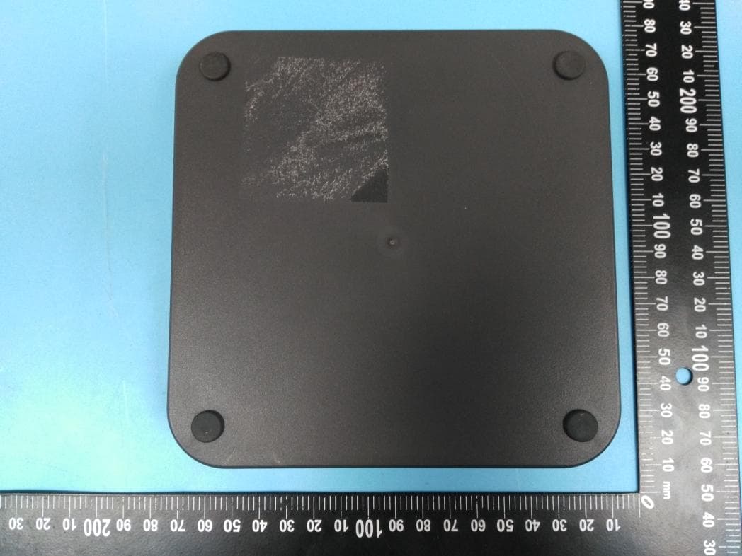
2AWK8IN5000
Sep 21, 2020INTRANAV NODE
Equipment Class
UWB - Ultra Wideband Transmitter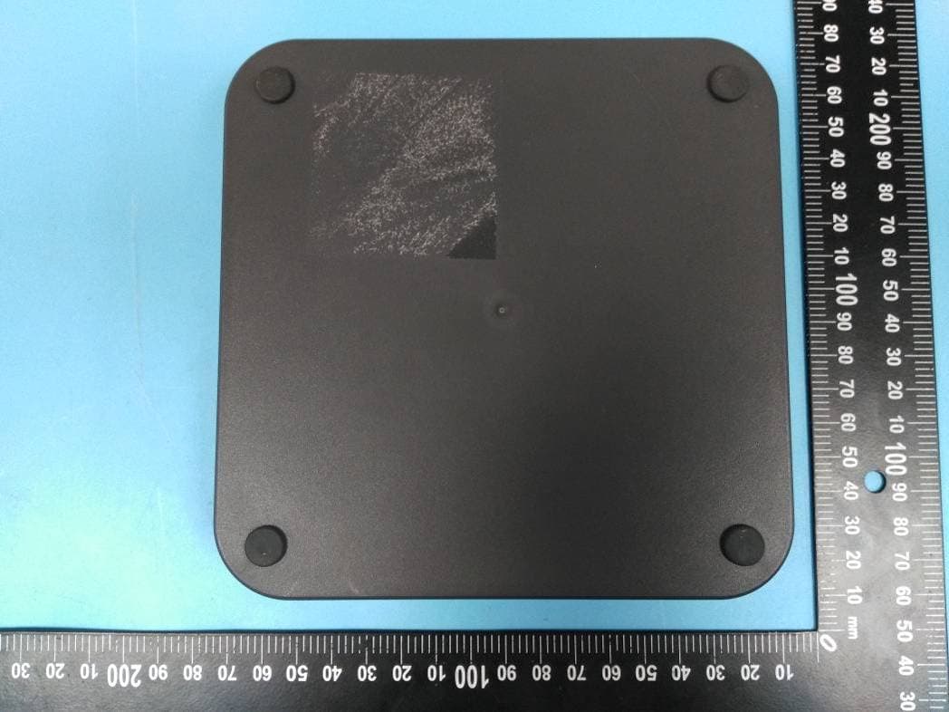
2AWK8IN5200
Aug 23, 2020INTRANAV NODE
Equipment Class
UWB - Ultra Wideband Transmitter