2AWLP-LPD10-11LUME PAD
Leia, Inc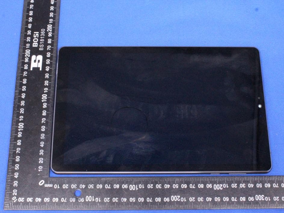
Click to zoom
Application Details
- Equipment Class
- NII - Unlicensed National Information Infrastructure TX
- Date of Grant
- Jul 05, 2020
- Application Purpose
- Original Equipment
- Date of Application
- Jul 05, 2020
- Equipment Note
- LUME PAD
- Frequency Range
- 5745.00000000 - 5825.00000000
- Company
- Leia, Inc
- Country
- United States
Documents & Files
Document Text
Text extracted from the exhibit documents filed with the FCC. Open a document above to read the original.
Users Manual
1 LEIA LUME PAD LPD-10W User Manual Equipment Part Drawing 2 1 Audio Jack 8 Sub Cam 16M 2 TypeC USB 9 Main Cam 16M 3 Light sensing 10 Flash 4 LED indicator 11 Volume up and down 5 Front Cam 8M 12 Power on/off 6 TOF Receiving unit 13 Speeker 7 TOF transmitter unit 14 Mic 15 Touch screen Product feature brief 1.10.8 inch 2k LCD(2560*1600),2D and 4V light field display。 2.Qualcomm 845,Android 10 3.Main Cam 16M,Sub Cam 8M, support TOF 4.Support many sensors,G-Sensor,Magnet sensor,etc 5. MultiMedia:Main Cam-4k video 30fps, 1080P video 30/60fps, 720P video 30/60/120fps;Sub Cam-2k video 30fps, 1080P video 30fps, 720P video 30/60fps 6.Storage:8+128 GB 7.Interface:Audio Jack 3.5mm、TypeC USB Product functions 3 ◆Power on/off ● Power on:In the power off state, press and hold the power key until the system enter into power on animation, will show lock screen in about 30 seconds, slide to unlock ● Power off:In the power on state, long press the power key for 3 seconds, the screen displays the shutdown confirmation interface, select the shutdown option, the system will shut down ◆Battery management and charging At the first time, you should charge the battery to 100% to make sure that it is fully charged and then use. B when the battery power is completely exhausted, please charge for at least 5 minutes and then restart. 【Attention】To ensure the best use of lithium battery, please pay attention to the following: ● do not charge in high temperature environment (such as balcony or direct sunlight). ● the lithium battery does not need to be discharged, nor does it need to run out of power before charging. You can charge when the battery is still charged. ● when the product is not used for a long time, please fully charge it at least once every two weeks to avoid over discharge of the battery which may affect its charging performance. ◆Function icon 4 ◆ APK install supports third-party applications based on Android platform, which can be obtained from the network for installation and use. Trust source needs to be opened in settings ◆ Camera 5 ◆Music 6 ◆ Video playback and picture browsing (Leia player) ◆ File Management Open the file management, you can select files under the corresponding folder according to the storage path, or display and download files according to different file types 7 8 ◆Browser Google Chrome, click the address bar, enter the website address, click go to and then browse the corresponding website information: 9 ◆ Calendar ◆ Calculator 10 ◆Clock 11 ◆ Setting ● WIFI Enter the system and automatically find the WiFi network name, as shown in the figure below, multiple WiFi network names have been found, click the network name and enter the password to connect 12 ● other connect ● Apps¬ifications 13 ●Battery ●Storage 14 ● Privacy ● Location 15 ● Security ● Accounts 16 ●Accessibiliy ● Digital Wellbeing & parental controls 17 ● Google ● System 18 ● About tablet ●Certification About tablet-Certification 19 ●Reset options Note that using the factory default mode will affect some functions and cause data loss ●Software update Before upgrading, please confirm that the tablet has not been installed with an unofficial version, otherwise there is a risk of upgrade failure and unknown problems may be introduced. Before upgrading, please ensure that the battery is above 30%. 20 Do not disconnect the USB cable during the upgrade process 21 ◆Precautions for use In order to give full play to the performance of the new tablet computer and avoid improper operation, please read this operation manual carefully before using this product, thank you. 1. Do not place the tablet computer in hot, cold, dusty, wet and other environments. 2. When using this product, do not let the tablet fall or make the hard object hit the screen, which will cause damage to the screen. The user shall be responsible for the product damage caused by man-made or other force majeure. 3. Try to avoid operating the tablet in a dry environment to prevent static electricity. 4. please charge in the following cases: A when the charging indicator is not green; B. the tablet automatically shuts down or turns on and off; Operation C did not respond. 5. Do not place heavy objects on the tablet, otherwise it will damage the tablet. 6. When the machine is used as a mobile hard disk, the user should export the file according to the correct file management operation method. The company will not be responsible for any loss of the file when the error occurs. 7. Because a small part of the memory space will be used by the software in the tablet computer and the memory capacity of the computer is in different decimal places, the memory capacity displayed in the operating system will be less than the standard value, which is in line with the relevant regulations. 22 8. If the memory changes or is damaged, so that the tablet cannot be used normally, the user can format the tablet on the computer. 9.Laser certification Note: the company reserves the right to improve products. The performance and function of products with different hardware and software versions may have some differences, so the changes will not be notified. FCC Statement Changes or modification not expressly approved by the party responsible 23 for compliance could void the user’s authority to operate the equipment. Note: This equipment has been tested and found to comply with the limits for a Class B digital device, pursuant to part 15 of the FCC Rules. These limits are designed to provide reasonable protection against harmful interference in a residential installation. This equipment generates, uses and can radiate radio frequency energy and, if not installed and used in accordance with the instructions, may cause harmful interference to radio communications. However, there is no guarantee that interference will not occur in a particular installation. If this equipment does cause harmful interference to radio or television reception, which can be determined by turning the equipmen…
Text truncated - open the document above for the full version.
Cover Letter(s)
Leia, Inc FCC Software Configuration Control Declaration Date: July 1, 2020 Federal Communications Commission 7435 Oakland Mills Road Columbia, MD 21046 USA Attn: OET Dept. Product/ Model Number: LUME PAD/ LPD-10W, LPD-11W Regarding FCC Country Code Selection guidelines identified in KDB 594280. “All applications for equipment authorization for transmitters that can have radio parameters, or other technical parameters, reported to the Commission set by software must have an attestation indicating that no third party will have software, or configuration control, to program the device out of compliance of the technical rules under which it has been certified.” We declare that no third party will have software, or configuration control, to program the device out of compliance of the technical rules under which it has been certified. Name: Xiuping XuDate: 2020/07/01 Title: Certification Manager Signature of applicant
Cover Letter(s)
Leia, Inc Of fice of Engineering Technology Federal Communications Commission 7435 Oakland Mills Road Columbia, MD 21046 USA Date: 2020.06.23 Subject; Request for Long Term Confidentiality FCC ID: 2AWLP-LPD10-11 To W hom It May Concern, Pursuant to the provisions of the Commission’s rules Title 47 Sections §0.457 and §0.459, we are requesting the Commission to withhold the following attachment(s) as confidential documents from public disclosure indefinitely. Thes e documents contain detailed system and equipment descriptions and are considered as proprietary information in operation of the equipment. The public disclosure of these documents might be harmful to our company and would give competitors an unfair advantage in the market. Schematic Diagram Block Diagram Parts List Operational Desc ription Tune-up Procedure Software Security Operational Description It is our understanding that all measurement test reports, FCC ID label format and correspondence during the certification review process cannot be granted as confidential documents and this information will be available for public review once the grant of equipment authorization is issued. Si ncerely, Si gnature: Nam e: Xiuping Xu Tit le: Certification Manager
Cover Letter(s)
Leia, Inc 2440 Sand Hill Road, STE 100, Menlo Park, California 94025, United States Statement P roduct: LUME PAD Model: LPD-10W Additional Model: LPD-11W Trademark: N/A We hereby state that All models above are identical in interior structure, electrical circuits and components, and just model names are different for the marketing requirement. Your assistance on this matter is highly appreciated. Y ours sincerely, S ignature: Date: 2020/06/23 N ame: Xiuping Xu Company Name : Leia, Inc Address: 2440 Sand Hill Road, STE 100, Menlo Park, California 94025, United States Tel / Fax: 650 488 6995/650 618 1821 E- Mail: [email protected]
Cover Letter(s)
Leia, Inc Agent Authorization C ompany: Leia, Inc A ddress: 2440 Sand Hill Road, STE 100, Menlo Park, California 94025, United States P roduct Name: LUME PAD M odel Number(s):LPD-10W, LPD-11W P roduct Description: LUME PAD W e authorize MiCOM Labs Inc., 575 Boulder Court, Pleasanton, California 94566, USA, to act on our behalf on all matters concerning the certification of above named equipment. W e declare that MiCOM Labs Inc. is allowed to forward all information related to the approval and certification of equipment to the regulatory agencies as required and to discuss any issues concerning the approval application. Any and all acts carried out by MiCOM Labs on our behalf shall have the same effect as acts of our own. Signature: Date: 2020-06-23 Name: Xiuping Xu Title: Certification Manager Company: Leia, Inc
External Photos
Page 1 of 4 Appendix C: Photographs of EUT Product: LUME PAD Model: LPD-10W External Photos Page 2 of 4 Page 3 of 4 Page 4 of 4
ID Label/Location Info
Label Artwork and Location Model: LPD-10W Label: Size: L*W=108*24mm Location
Internal Photos
Page 1 of 5 Appendix C: Photographs of EUT Product: LUME PAD Model: LPD-10W Internal Photos BT/BLE ANT WIFI ANT 0 WIFI ANT 1 Page 2 of 5 Page 3 of 5 Page 4 of 5 Page 5 of 5
RF Exposure Info
Any reproduction of this document must be done in full. No single part of this document may be reproduced without permission from STS, All Test Data Presented in this report is only applicable to presented Test sample. ShenZhen STS Test Services Co.,Ltd. A 1/F, Building B, Zhuoke Science Park, No.190 Chongqing Road, HepingShequ, Fuyong Sub-District, Bao’an District, Shenzhen, Guang Dong, China TEL: +86-755 3688 6288 FAX: +86-755 3688 6277 E-mail:[email protected] S T L A B S Testing Engineer : (Aaron Bu) Technical Manager : (Jason Lu) Authorized Signatory : (Vita Li) SAR Dipole Performance Measurement Report EUT Type: SAR Validation Dipole and Waveguide Model Name: WAG32 Brand Name: SATIMO Test Conclusion: Pass Test Date: 16 Aug. 2019 Date of Issue: 17 Aug. 2019 ISSUED BY Shenzhen STS Test Services Co., Ltd. 1. Equipment List Kind of Equipment Manufacturer Type No. Serial No. Last Calibration Calibrated Until PC Acer N/A N/A N/A N/A E-Field Probe MVG SSE5 SN 14/16 EP309 2018.12.13 2019.12.12 Dielectric Probe Kit MVG SCLMP SN 32/14 OCPG67 2018.12.01 2019.11.30 Phantom1 MVG SAM SN 32/14 SAM115 N/A N/A Phantom2 MVG SAM SN 32/14 SAM116 N/A N/A Attenuator Agilent 99899 DC-18GHz N/A N/A Directional coupler Narda 4226-20 3305 N/A N/A Network Analyzer Agilent 8753ES US38432810 2019.03.02 2020.03.01 Multi Meter Keithley Multi Meter 2000 4050073 2018.10.13 2019.10.12 Signal Generator Agilent N5182A MY50140530 2018.10.16 2019.10.15 Power Amplifier DESAY ZHL-42W 9638 2018.10.13 2019.10.12 Power Meter R&S NRP 100510 2018.10.26 2019.10.25 Power Sensor R&S NRP-Z11 101919 2018.10.13 2019.10.12 Power Sensor Agilent E9301A MY41497725 2018.10.13 2019.10.12 hygrothermograph MiEO HH660 N/A 2018.10.11 2019.10.10 Thermograph Elitech RC-4 S/N EF7176501537 2018.10.15 2019.10.14 ISSUED BY Shenzhen STS Test Services Co., Ltd. 2. <Justification of the extended calibration> Referring to KDB 865664 D01, if dipoles are verified in return loss<-20dB, (within 20% of prior calibration), and in impedance (within 5 ohm of prior calibration), the annual calibration is not necessary and the calibration interval can be extended. Body 5000 MHz Date of Measurement Return Loss (dB) Delta (%) Impedance Delta(ohm) 2017.08.15 < -13.94 - - - 2018.08.16 -14.41 - - - 2019.08.16 -14.61 - - - The return loss is <-8dB, within 20% of prior calibration; Therefore the verification result should support extended calibration. <Dipole Verification Data> Body 5000MHz
RF Exposure Info
Ref : ACR.348.1.20.SATU.A SHENZHEN STS TEST SERVICES CO., LTD. 1/F., BUILDING B, ZHUOKE SCIENCE PARK, No.190, CHONGQING ROAD,FUYONG STREET BAO’AN DISTRICT,SHENZHEN,GUANGDONG,CHINA MVG COMOSAR DOSIMETRIC E-FIELD PROBE SERIAL NO.: SN 45/15 EPGO281 Calibrated at MVG US 2105 Barrett Park Dr. - Kennesaw, GA 30144 Calibration Date: 04/07/ 2020 Summary: This document presents the method and results from an accredited COMOSAR Dosimetric E-Field Probe calibration performed in MVG USA using the CALISAR / CALIBAIR test bench, for use with a COMOSAR system only. All calibration results are traceable to national metrology institutions. COMOSAR E-Field Probe Calibration Report COMOSAR E-FIELD PROBE CALIBRATION REPORT Ref: ACR.348.1.20.SATU.A Page: 2/10 This document shall not be reproduced, except in full or in part, without the written approval of MVG. The information contained herein is to be used only for the purpose for which it is submitted and is not to be released in whole or part without written approval of MVG. Name Function Date Signature Prepared by : Jérôme LUC Product Manager 04/15/2020 Checked by : Jérôme LUC Product Manager 04/15/2020 Approved by : Kim RUTKOWSKI Quality Manager 04/15/2020 Customer Name Distribution : Shenzhen STS Test Services Co., Ltd. Issue Date Modifications A 04/15/2020Initial release COMOSAR E-FIELD PROBE CALIBRATION REPORT Ref: ACR.348.1.20.SATU.A Page: 3/10 This document shall not be reproduced, except in full or in part, without the written approval of MVG. The information contained herein is to be used only for the purpose for which it is submitted and is not to be released in whole or part without written approval of MVG. TABLE OF CONTENTS 1 Device Under Test ..................................................................................................... 4 2 Product Description ................................................................................................... 4 2.1 General Information _______________________________________________________ 4 3 Measurement Method ................................................................................................ 4 3.1 Linearity ________________________________________________________________ 4 3.2 Sensitivity _______________________________________________________________ 5 3.3 Lower De tection Limit _____________________________________________________ 5 3.4 I sotropy _________________________________________________________________ 5 3.5 Boundar y Effect __________________________________________________________ 5 4 Measure ment Uncertainty .......................................................................................... 5 5 Calibration Measurement Results .............................................................................. 6 5.1 Sensitivity in air __________________________________________________________ 6 5.2 Linearity ________________________________________________________________ 7 5.3 Sensit ivity in liquid ________________________________________________________ 7 5.4 Isotropy _________________________________________________________________ 8 6 List of Equipment .................................................................................................... 10 COMOSAR E-FIELD PROBE CALIBRATION REPORT Ref: ACR.348.1.20.SATU.A Page: 4/10 This document shall not be reproduced, except in full or in part, without the written approval of MVG. The information contained herein is to be used only for the purpose for which it is submitted and is not to be released in whole or part without written approval of MVG. 1 DEVICE UNDER TEST Device Under Test Device Type COMOSAR DOSIMETRIC E FIELD PROBE Manufacturer MVG Model SSE2 Serial Number SN 45/15 EPGO281 Product Condition (new / used) New Frequency Range of Probe 0.45 GHz-6GHz Resistance of Three Dipoles at Connector Dipole 1: R1=0.183 M Dipole 2: R2=0.191 M Dipole 3: R3=0.19 6 M A yearly calibration interval is recommended. 2 PRODUCT DESCRIPTION 2.1 GENERAL INFORMATION MVG’s COMOSAR E field Probes are built in accordance to the IEEE 1528, OET 65 Bulletin C and CEI/IEC 62209 standards. Figure 1 – MVG COMOSAR Dosimetric E field Dipole Probe Length 330 mm Length of Individual Dipoles 2 mm Maximum external diameter 8 mm Probe Tip External Diameter 2.5 mm Distance between dipoles / probe extremity 1 mm 3 MEASUREMENT METHOD The IEEE 1528, OET 65 Bulletin C, CENELEC EN50361 and CEI/IEC 62209 standards provide recommended practices for the probe calibrations, including the performance characteristics of interest and methods by which to assess their affect. All calibrations / measurements performed meet the fore mentioned standards. 3.1 LINEARITY The evaluation of the linearity was done in free space using the waveguide, performing a power sweep to cover the SAR range 0.01W/kg to 100W/kg. COMOSAR E-FIELD PROBE CALIBRATION REPORT Ref: ACR.348.1.20.SATU.A Page: 5/10 This document shall not be reproduced, except in full or in part, without the written approval of MVG. The information contained herein is to be used only for the purpose for which it is submitted and is not to be released in whole or part without written approval of MVG. 3.2 SENSITIVITY The sensitivity factors of the three dipoles were determined using a two step calibration method (air and tissue simulating liquid) using waveguides as outlined in the standards. 3.3 LOWER DETECTION LIMIT The lower detection limit was assessed using the same measurement set up as used for the linearity measurement. The required lower detection limit is 10 mW/kg. 3.4 ISOTROPY The axial isotropy was evaluated by exposing the probe to a reference wave from a standard dipole with the dipole mounted under the flat phantom in the test configuration suggested for system validations and checks. The probe was rotated along its main axis from 0 - 360 degrees in 15 degree steps. The hemispherical isotropy is determined by inserting the probe in a thin plastic box filled with tissue-equivalent l…
Text truncated - open the document above for the full version.
RF Exposure Info
Any reproduction of this document must be done in full. No single part of this document may be reproduced without permission from STS, All Test Data Presented in this report is only applicable to presented Test sample. ShenZhen STS Test Services Co.,Ltd. A 1/F, Building B, Zhuoke Science Park, No.190 Chongqing Road, HepingShequ, Fuyong Sub-District, Bao’an District, Shenzhen, Guang Dong, China TEL: +86-755 3688 6288 FAX: +86-755 3688 6277 E-mail:[email protected] FCC SAR TEST REPORT Report No.: STS2006297H01 Issued for Leia, Inc 2440 Sand Hill Road, STE 100, Menlo Park, California 94025, United States Product Name: LUME PAD Brand Name: N/A Model Name: LPD-10W Series Model: LPD-11W FCC ID: 2AWLP-LPD10-11 Test Standard: ANSI/IEEE Std. C95.1 FCC 47 CFR Part 2 ( 2.1093) IEEE 1528: 2013 Max. Report SAR (1g): Body:0.821 W/kg S T L A B S Page 2 of 43 Report No.: STS2006297H01 Test Report Certification Applicant’s name ................. : Leia, Inc Address ................................. : 2440 Sand Hill Road, STE 100, Menlo Park, California 94025, United States Manufacture's Name ............ : Leia, Inc Address ................................. : 2440 Sand Hill Road, STE 100, Menlo Park, California 94025, United States Product description Product name ........................ : LUME PAD Brand name ......................... : N/A Model name ......................... : LPD-10W Series Model .......................... : LPD-11W Standards ............................. : ANSI/IEEE Std. C95.1-1992 FCC 47 CFR Part 2 ( 2.1093) IEEE 1528: 2013 The device was tested by Shenzhen STS Test Services Co., Ltd. in accordance with the measurement methods and procedures specified in KDB 865664 The test results in this report apply only to the tested sample of the stated device/equipment. Other similar device/equipment will not necessarily produce the same results due to production tolerance and measurement uncertainties. Date of Test ........................................... : Date (s) of performance of tests ............. : 28 May 2020~12 June 2020 Date of Issue .......................................... : 15 June 2020 Test Result.............................................. : Pass Testing Engineer : ( Aaron Bu) Technical Manager : (Jason Lu) Authorized Signatory : (Vita Li) Page 3 of 43 Report No.: STS2006297H01 Table of Contents 1.General Information 5 1.1 EUT Description 5 1.2 Test Environment 6 1.3 Test Factory 6 2. Test Standards and Limits 7 3. SAR Measurement System 8 3.1 Definition Of Specific Absorption Rate (SAR) 8 3.2 SAR System 8 4. Tissue Simulating Liquids 11 4.1 Simulating Liquids Parameter Check 11 5. SAR System Validation 13 5.1 Validation System 13 5.2 Validation Result 13 6. SAR Evaluation Procedures 14 7. EUT Antenna Location Sketch 15 7.1 SAR test exclusion consider table 16 8. EUT Test Position 18 8.1 Define Two Imaginary Lines On The Handset 18 9. Uncertainty 19 9.1 Measurement Uncertainty 19 9.2 System validation Uncertainty 20 10. Conducted Power Measurement 21 10.1 Test Result 21 11. EUT And Test Setup Photo 22 11.1 EUT Photo 22 11.2 Setup Photo 25 12. SAR Result Summary 29 12.1 Body-worn and Hotspot SAR 29 12.2 repeated SAR measurement 31 13. Equipment List 32 Appendix A. System Validation Plots 33 Appendix B. SAR Test Plots 37 Appendix C. Probe Calibration And Dipole Calibration Report 43 Page 4 of 43 Report No.: STS2006297H01 Revision History Rev. Issue Date Report No. Effect Page Contents 00 15 June 2020 STS2006297H01 ALL Initial Issue Note: Format version of the report -V01 Page 5 of 43 Report No.: STS2006297H01 1. General Information Environmental evaluation measurements of specific absorption rate (SAR) distributions in emulated human head and body tissues exposed to radio frequency (RF) radiation from wireless portable devices for compliance with the rules and regulations of the U.S. Federal Communications Commission (FCC). 1.1 EUT Description Product Name LUME PAD Brand Name N/A Model Name LPD-10W Series Model LPD-11W Model Difference All models above are identical in interior structure, electrical circuits and components, and just model names are different for the marketing requirement. AC adapter Adapter Information: Model: A138A-120150U-US4 Input: AC 100-240V, 50/60Hz, 0.5A Output: DC 5V, 3A/DC 9V, 2A/DC 12V, 1.5A Power Supply Rechargeable Li-ion Battery DC 3.85V Device Category Portable Product stage Production unit RF Exposure Environment General Population / Uncontrolled Hardware Version N/A Software Version N/A Frequency Range 5GHz WLAN IEEE 802.11a/n/ac (20MHz): 5180MHz to 5240MHz, 5745MHz to 5825MHz 5GHz WLAN IEEE 802.11n/ac (40MHz): 5190MHz to 5230MHz, 5755MHz to 5795MHz 5GHz WLAN IEEE 802.11ac (80MHz): 5210MHz, 5775MHz Max. Reported SAR(1g): (Limit:1.6W/kg) Band Mode Body Worn and Hotspot(W/kg) NII 5.2G WLAN ANT 0 0.762 NII 5.2G WLAN ANT 1 0.821 NII 5.2G WLAN MIMO(ANT 0+1) 0.795 NII 5.8G WLAN ANT 0 0.807 NII 5.8G WLAN ANT 1 0.791 NII 5.8G WLAN MIMO(ANT 0+1) 0.817 FCC Equipment Class Unlicensed National Information Infrastructure TX (NII) Operating Mode: 802.11a(OFDM): BPSK,QPSK,16-QAM,64-QAM 802.11n(OFDM): BPSK,QPSK,16-QAM,64-QAM 802.11ac(OFDM): BPSK,QPSK,16-QAM,64-QAM,256-QAM Antenna Gain WIFI 5.2G: Antenna 0: 1.75dBi, Antenna 1: 1.47dBi WIFI 5.8G: Antenna 0: 0.8dBi, Antenna 1: 1.0dBi Antenna Specification: WLAN: Internal Antenna Hotspot Mode: Support DTM Mode: Not Support Note: 1. The EUT battery must be fully charged and checked periodically during the test to ascertain uniform power Page 6 of 43 Report No.: STS2006297H01 1.2 Test Environment Ambient conditions in the SAR laboratory: Items Required Temperature (°C) 18-25 Humidity (%RH) 30-70 1.3 Test Factory ShenZhen STS Test Services Co.,Ltd. A 1/F, Building B, Zhuoke Science Park, No.190 Chongqing Road, HepingShequ, Fuyong Sub-District, Bao’an District, Shenzhen, Guang Dong, China FCC test Firm Registration No.: 625569 IC Registration No.: 12108A A2LA Certificate No.: 4338.01 Page 7 of 43 Report No.: STS20062…
Text truncated - open the document above for the full version.
Test Report
Hotline: 400-6611-140 Tel: 86-755-27673339 Fax: 86-755-27673332 http://www.tct-lab.com TEST REPORT FCC ID: 2AWLP-LPD10-11 Product: LUME PAD Model No.: LPD-10W Additional Model No.: LPD-11W Trade Mark: N/A Report No.: TCT200527E010 Issued Date: Jun. 15, 2020 Issued for: Leia, Inc 2440 Sand Hill Road, STE 100, Menlo Park, California 94025, United States Issued By: Shenzhen Tongce Testing Lab. 1B/F., Building 1, Yibaolai Industrial Park, Qiaotou, Fuyong, Baoan District, Shenzhen, Guangdong, China TEL: +86-755-27673339 FAX: +86-755-27673332 Note: This report shall not be reproduced except in full, without the written approval of Shenzhen Tongce Testing Lab. This document may be altered or revised by Shenzhen Tongce Testing Lab. personnel only, and shall be noted in the revision section of the document. The test results in the report only apply to the tested sample. Report No.: TCT200527E010 Page 2 of 104 Hotline: 400-6611-140 Tel: 86-755-27673339 Fax: 86-755-27673332 http://www.tct-lab.com TABLE OF CONTENTS 1. Test Certification ...................................................................................... 3 2. Test Result Summary ............................................................................... 4 3. EUT Description ........................................................................................ 5 4. General Information .................................................................................. 7 4.1. Test environment and mode ................................................................................ 7 4.2. Description of Support Units ............................................................................... 8 5. Facilities and Accreditations ................................................................... 9 5.1. Facilities ................................................................................................................ 9 5.2. Location ................................................................................................................. 9 5.3. Measurement Uncertainty .................................................................................... 9 6. Test Results and Measurement Data ..................................................... 10 6.1. Antenna requirement .......................................................................................... 10 6.2. Conducted Emission .......................................................................................... 11 6.3. Maximum Conducted Output Power ................................................................. 15 6.4. 6dB Emission Bandwidth ................................................................................... 19 6.5. 26dB Bandwidth and 99% Occupied Bandwidth .............................................. 32 6.6. Power Spectral Density ...................................................................................... 55 6.7. Band edge ........................................................................................................... 78 6.8. Unwanted Emission ............................................................................................ 88 6.9. Frequency Stability Measurement ..................................................................... 99 Appendix A: Photographs of Test Setup Appendix B: Photographs of EUT Report No.: TCT200527E010 Page 3 of 104 Hotline: 400-6611-140 Tel: 86-755-27673339 Fax: 86-755-27673332 http://www.tct-lab.com 1. Test Certification Product: LUME PAD Model No.: LPD-10W Additional Model No.: LPD-11W Trade Mark: N/A Applicant: Leia, Inc Address: 2440 Sand Hill Road, STE 100, Menlo Park, California 94025, United States Manufacturer: Leia, Inc Address: 2440 Sand Hill Road, STE 100, Menlo Park, California 94025, United States Date of Test: May 28, 2020 – Jun. 12, 2020 Applicable Standards: FCC CFR Title 47 Part 15 Subpart E Section 15.407: 2016 KDB662911 D01 Multiple Transmitter Output v02r01 KDB789033 D02 General U-NII Test Procedures New Rules v02r01 The above equipment has been tested by Shenzhen Tongce Testing Lab. and found compliance with the requirements set forth in the technical standards mentioned above. The results of testing in this report apply only to the product/system, which was tested. Other similar equipment will not necessarily produce the same results due to production tolerance and measurement uncertainties. Tested By: Date: Jun. 12, 2020 Brews Xu Reviewed By: Date: Jun. 15, 2020 Beryl Zhao Approved By: Date: Jun. 15, 2020 Tomsin Report No.: TCT200527E010 Page 4 of 104 Hotline: 400-6611-140 Tel: 86-755-27673339 Fax: 86-755-27673332 http://www.tct-lab.com 2. Test Result Summary Requirement CFR 47 Section Result Antenna requirement §15.203 PASS AC Power Line Conducted Emission §15.207 PASS Maximum Conducted Output Power §15.407(a) PASS 6dB Emission Bandwidth §15.407(a) PASS 26dB Emission Bandwidth& 99% Occupied Bandwidth §15.407(a) PASS Power Spectral Density §15.407(a) PASS Restricted Bands around fundamental frequency §15.407(a) PASS Radiated Emission §15.407(a) PASS Frequency Stability §15.407(g) PASS Note: 1. PASS: Test item meets the requirement. 2. Fail: Test item does not meet the requirement. 3. N/A: Test case does not apply to the test object. 4. The test result judgment is decided by the limit of test standard. Report No.: TCT200527E010 Page 5 of 104 Hotline: 400-6611-140 Tel: 86-755-27673339 Fax: 86-755-27673332 http://www.tct-lab.com 3. EUT Description Product: LUME PAD Model No.: LPD-10W Additional Model No.: LPD-1…
Text truncated - open the document above for the full version.
Contact Information
Applicant
Xiuping Xu(Certification Manager)
Technical Contact
Test Firm
SHENZHEN TONGCE TESTING LABBeryl Zhao
[email protected]+8675527208735
Technical Specifications
| # | Rule Parts | Frequency Range | Power Output |
|---|---|---|---|
| 2 | 15E | 5.75 GHz - 5.83 GHz | 5.73 mW |