2AWQGX10001MACH6
SICHUAN AEE AVIATION TECHNOLOGY CO., LTD.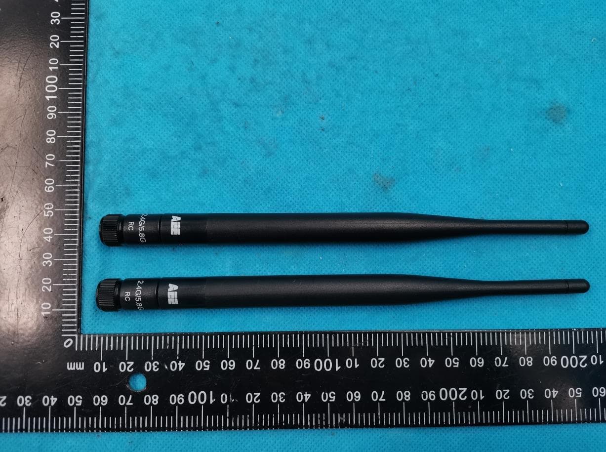
Click to zoom
Application Details
- Equipment Class
- PCB - PCS Licensed Transmitter
- Date of Grant
- Aug 14, 2022
- Application Purpose
- Original Equipment
- Date of Application
- Aug 14, 2022
- Equipment Note
- MACH6
- Frequency Range
- 1720.00000000 - 1770.00000000
- Country
- China
Documents & Files
Document Text
Text extracted from the exhibit documents filed with the FCC. Open a document above to read the original.
Users Manual
V1.0 USER'S MANUAL Before flying this aircraft, please read this manually carefully and completely. Keep it safe for later reference. Pictures only for reference. AEE UNMANNED AIRCRAFT SYSTEM Professional Leading Product name: MACH6 Model Name: Y12 General Manager of AEE Technology Inc. Welcome message from the General Manager of AEE Technology Inc. 6 Table of Contents 1. Introduction...........................................................................................................................................1 1.1 Introduction....................................................................................................................................1 1.2 Safety Precautions........................................................................................................................1 1.3 UAV Preparation...........................................................................................................................3 1.4 Installation of remote controller antenna.....................................................................................11 2. Aircraft ..............................................................................................................................................12 2.1 Overview of aircraft ....................................................................................................................12 2.2 Flight mode ................................................................................................................................12 2.3 Navigation and Status Lights......................................................................................................12 2.4 Auto takeoff/landing ...................................................................................................................13 2.5 One-button route .......................................................................................................................13 2.6 Auto return .................................................................................................................................15 2.7 Radar avoidance function ..........................................................................................................16 2.8 RTK ............................................................................................................................................17 2.9 Point selection flight ...................................................................................................................18 3. Intelligent Battery ..............................................................................................................................18 3.1 Introduction ................................................................................................................................18 3.2 Functions ...................................................................................................................................18 3.3 Use of intelligent battery ............................................................................................................19 3.4 View battery level ......................................................................................................................19 4. Illustration and Functional Introduction of Remote Control and Drone Parts.....................................21 4.1 Illustration and functional introduction of remote control parts and drone parts..........................21 4.2 Illustration of drone parts ............................................................................................................23 5. Remote Control .................................................................................................................................24 5.1 Operation of remote control .......................................................................................................24 5.2 Remote control on/off ................................................................................................................24 5.3 Battery level of remote control ...................................................................................................25 5.4 Drone operation .........................................................................................................................26 5.5 Flight mode switch .....................................................................................................................29 5.6 Illustration and function for main interface of remote control .....................................................30 5.7 Illustration of setting interface ....................................................................................................35 5.8 Illustration of Map interface ........................................................................................................43 5.9 Route mission ............................................................................................................................47 6. Flight ................................................................................................................................................58 6.1 Take-off preparation ..................................................................................................................58 6.2 Requirements of flight environment ..........................................................................................58 6.3 Compass correction ..................................................................................................................58 6.4 Manual on/off ............................................................................................................................59 6.5 Basic flight ................................................................................................................................60 6.6 Usage process of GS software route planning task ....................…
Text truncated - open the document above for the full version.
Users Manual
- 7 - 1.3.5 Attach & removal of gimbal and payload mount 1.3.5.1 Align the two pins (shown in red) of the gimbal with the clamping holder (shown in red) of the gimbal and insert them into it (observe it carefully during installation, to avoid contact with the pin at end of drone); push the gimbal to the clamping position until there’s “click” sound, make sure the gimbal is clamped, and check if it is installed properly, as shown below: 1.3.5.2 Removal of gimbal Removal the cradle head according to the arrow direction. As shown below: While removal the cradle head, hold the cradle head with one hand and removal it with another hand, to avoid falling and damage of cradle head. 2 1 AEE Unmanned Aircraft Syst em - 8 - 1.3.5.3 Installation of payload mount Push in the payload mount according to the arrow direction in diagram until there’s “click” sound, make sure the payload mount is clamped and check if it is installed properly. As shown in figure below: AEE Unmanned Aircraft Syst em 1.3.5.4 Removal of payload mount Removal the payload mount according to the diagram. As shown in figure below: 1 2 1 2 - 9 - Removal of double payload mounts. As shown in figure below: Prompt: While removal the payload mount, hold the unlock button with one hand, hold the payload mount with another hand and move it out slowly according to the direction in diagram, to avoid falling and damage of payload mount during removal. 1.3.6 Installation & removal of smart battery 1.3.6.1 Installation of smart battery Push the battery into the battery warehouse according to the direction in diagram, make sure the battery lock can be fastened and check if the battery is installed properly. As shown in figure below: AEE Unmanned Aircraft Syst em 12 12 34 - 10 - 1.3.6.2 Removal of intelligent battery Open the battery lock and take out the battery, as shown in figure below: Note: If the battery or its lock is not fastened normally, it may lead to poor contact of power supply, affect the flying safety, even flying failure and affect the flying experience. AEE Unmanned Aircraft Syst em 1 2 3 3 - 11 - 1.4 Installation of remote controller antenna As shown in figure below: 1.4.1 Removal of hood As shown in figure below: 1.4.2 Installation and removal of safety buckle and rope of remote control 1.4.2.1 Installation of rope As shown in figure below: AEE Unmanned Aircraft Syst em
Users Manual
- 12 - 1.4.2.2 Removal of rope As shown in figure below: AEE Unmanned Aircraft Syst em 2. Aircraft 2.1 Overview of aircraft The Mach6 aircraft mainly consists of flight control system, communication system, locating system, power system and intelligent flight battery. The functions of all parts will be introduced in details in this chapter. 2.2 Flight mode High Velocity Mode: This mode is the same as the POS HOLD Mode(GPS), the max horizontal flight speed is increased, and the max speed 75.5ft/s. POS HOLD Mode: The drone can suspend based on its sensor and its suspension level and position depend on the satellite locating quality. It is recommended to enter this mode in general operation.Max speed 59.1ft/s. ATTI mode: Please use this mode with caution, for the drone can maintain the height but fail to maintain the horizontal position in this mode and it may have drifting. This mode does not apply to a beginner. 2.3 Navigation and Status Lights The drone includes nose LED indicator and drone status indicator. As shown in figure below: - 13 - AEE Unmanned Aircraft Syst em The nose LED indicator shows the nose direction of drone and the white light will be normally on after the drone is started. The tail LED indicator shows the current status of flight control system. Please refer to the status of flight control system represented by flickering modes. 2.4 Auto takeoff/landing The MACH6 drone supports one-key takeoff and landing. Press “One-key takeoff/landing” button and enter “ ” to set the takeoff height. Steps of use. 1. Enter “ ” in the main interface of remote control and set the takeoff height in “UAV setting interface – Takeoff height”. The default takeoff height is 16.4041995(ft); the min. and max. takeoff height are 16.4041995(ft) and 393.7007874(ft) respectively. 2. Once height setting is done, short press “One-button takeoff/landing” button of remote control, the main interface of remote control will pop up the dialogue box of “Are you sure to enter one-button takeoff?”; the drone will unlock vertical takeoff and suspend at the designated height. 3. Short press again and the main interface of remote control will pop up dialogue box of “Are you sure to land?”; the drone will land vertically and lock the propellers automatically. 2.5 One-button route The MACH6 drone supports one-button auto route mission. Press “One-button route” on remote control or enter the map to set “ ” “Edit route” “Execute route”. Steps of use: Introduction to drone status indicators Normal status Power-on self-test High Velocity Mode POS HOLD Mode ATTI mode Return flight Upgrade firmware Compass calibration: Accelerator calibration: Battery level alarm Warning and fault Battery level alarm Drone and remote control signal is lost During power-on self-test, the tail LED will flicker alternatively in red, yellow, purple and green; it will become red when self-test is passed When GPS signal is sufficiently acquired, the Tail LED will be Green. If GPS signal is not sufficient the LED will be Red. When GPS signal is sufficiently acquired, the Tail LED will be Green. If GPS signal is not sufficient the LED will be Red. The tail LED is normally on in red. The tail light flickers alternatively between purple and green. The blue light flickers quickly during upgrade. Slow flickering from yellow light to green light. When satellite signal is received and locked, the green light will be normally on; otherwise, the red light will be normally on. Calibration mode is entered when blue light is on; the blue light flickers during calibration; when calibration is done, the blue light is normally on; the green light will be normally on when level calibration is done. Battery level alarm Battery level alarm Drone and remote control signal is lost - 14 - AEE Unmanned Aircraft Syst em 2. When upload is done, short press “One-button route” on remote control, or enter map and press “Execute route” in “Edit route”, the main interface of remote control will pop up dialogue box “Are you sure to execute route?”, the drone will unlock automatically and execute the route mission. Once the mission is completed, the drone will return, land and lock the propellers automatically. 1. Firstly, edit a route mission and upload it to the drone. Please refer to “5.9 Route mission”. - 15 - AEE Unmanned Aircraft Syst em 2.6 Auto return The Mach 6 supports Return to Hom (RTH) function. The Home Point is defined point at which the GPS signal is acquired. When the communication signal is lost between the remote and the drone, RTH is initiated automatically. The Mach 6 supports 4 RTH modes, one button return, low battery alert return, mission completion return, and control signal loss return. 2.6.2 Low battery return (auto calculation function will be further added) The low battery return can be set in “ ” and the drone will return automatically in case of low battery. 2.6.1 One-button return Press “One-button return” key on remote control to trigger one-button return. The user may use one- button return function when the drone is beyond the visible range and the nose direction is unknown. Return height: When drone height is lower than 49 ft, the drone will firstly climb to the height of 49ft and then start returning. When drone height is over 49ft, the drone will return directly at the current height. During return, the drone’s flight mode will become “return”; meanwhile, the tail green light and purple light will flicker alternatively. The user can quit the return mode through “Flight mode switch” on the remote control, to control the drone again. Note: 1. It is recommended to enter the middle position (POS HOLD Mode) after flight mode is switched. 2. If the switch is pulled to down position (ATTI Mode), pay close attention to the drone to avoid safety accident. As the default setting, the return when the first-level alarm is triggered, or the drone will land when the second-level alarm is triggered. This function can be changed through user setting,…
Text truncated - open the document above for the full version.
Users Manual
- 29 - AEE Unmanned Aircraft Syst em 5.5 Flight mode switch 5.5.1 Pull this switch to control the flight mode of drone. The switch position is as shown below: 5.5.2 Flight mode status and prompt High Velocity Mode: This mode is the same as the POS HOLD Mode(GPS), the max horizontal flight speed is increased, and the max speed 75.5ft/s. POS HOLD Mode (GPS): 1. GPS satellite searching in progress warning appears when there is SAT are being acquired. 2. SAT signal strength of satellite icon on remote control is <3 Bars, the tail light will become red. When satellite signal strength is ≥3 Bars , the tail light will become green. 3. When all signals are weak (satellite signal is <- Bars, the tail light is red. 4. Max speed 59.1ft/s ATTI mode: 1. The drone can be unlocked until satellite is received. Meanwhile, the screen of remote control will prompt in every 2s: The drone may drift in ATTI mode, please use with caution! 2. The buzzer of remote control has beep sound. Tail light of drone is in red. Note: 1. AEE recommends that pilots should select the flight mode with caution. POS HOLD Mode (GPS) is recommended for the safest flying. 2. The ATTI Mode can be selected by experienced user, to help where GPS is limited to allow the drone to fly higher inorder to get a better GPS signal. After launch, please switch to POS hold or GPS lock when SAT signal allows. Pay close attention to the drone and control it to avoid an accident, for the drone may drift at different directions during hovering as GPS or RTK module fails to have accurate positioning and the height of drone is fixed only by barometer in this mode. It is recommended to switch the drone to POS HOLD Mode (GPS) (Middle) when satellite signal becomes better. Up High Velocity Mode Middle POS HOLD Mode (GPS) Down ATTI Mode - 30 - AEE Unmanned Aircraft Syst em 5.6 Illustration and function for main interface of remote control Return Arrow Main Menu Hide Window Arrow Shortcut Key Map Switch Window Information Bar Switch GPS/RTK Number of Satellites Altitude Flight Mode Remote Control Battery Coordinate of Latitude and Longitude Aircraft Heading Angle Setting Radar Status Aircraft Battery RangeSpeedFlight Clock Overlay Window Display Radar Detection Range Gesture Reference Line - 31 - AEE Unmanned Aircraft Syst em 5.6.1 Shortcut function 5.6.1.1 Camera shortcut Information bar switchOpen and hide “flight clock” and “coordinate of latitude and longitude” SpeedDisplay current flight speed of aircraft AltitudeDisplay current flight height of aircraft RangeDisplay current flight range of aircraft Flight modeDisplay current flight mode of aircraft Aircraft batteryDisplay the remaining battery level of aircraft Remote control batteryDisplay the remaining battery level of remote control SettingEnter the setting interface; for details, please refer to “5.7 Illustration of setting interface” Aircraft heading angleDisplay current flight direction (angle) of aircraft Gesture reference lineDisplay the current flight gesture and angle of aircraft Overlay window View and select other program tasks Main menuReturn to main menu of ground station Return keyPress twice to quit the program task Shortcut key This function key needs to be set manually. There’s no screenshot key by default. Hide window arrow Press it once to switch to map interface; press it again to return to main interface. Gesture reference linePress once to hide the map switch window 4G signal strength and air traffic control status 1. When SIM card is not inserted, the 4G icon and signal strength icon is in grey; 2. When SIM card is inserted, 4G icon will be on and it will indicate the corresponding signal strength; 3. When network and air traffic control platform are connected, it will display the air traffic control status; which means, the information of air traffic control status is reported. Display radar detection range It will display distance prompt when radar is enabled, or hide the distance prompt when radar is disabled. Color prompt: The color includes green, yellow and green; it will show red alert when obstacle occurs within 10m, show yellow prompt when obstacle occurs within 10-20m, or show green prompt when obstacle occurs within 20-40m; meanwhile, the drone will slow down. This function is designed to decelerate the drone and stop it within 10m when it has forward flying at high speed. Radar statusDisplay whether current aircraft has enabled radar Coordinate of latitude and longitude Display the coordinate of latitude and longitude of current aircraft Flight clockStart counting when drone takes off and record the flight period GPS/RTK Number of satellites Display current quantity of satellite and current flight mode of aircraft; for details, please refer to 5.5.2 Flight mode status and prompt - 32 - DAT9BQuickly control the gimbal angle and zoom of the cradle head, as shown in the figure below: DATFShortcut controls for DATF Pitch Angle and Camera controlsas shown in the figure below: AEE Unmanned Aircraft Syst em - 33 - 5.6.1.2 Spotlight shortcut Control the spotlight on/flash/off, control the cradle head pitch, as shown in the figure below: 5.6.1.3 Thunderhorn shortcut Control the Thunderhorn on/off, as shown in the figure below: AEE Unmanned Aircraft Syst em - 34 - DAR6 SUPER THUNDERHORN shortcut, as shown in the figure below: 5.6.1.4 DATE Mapping camera shortcut As shown in the figure below: AEE Unmanned Aircraft Syst em - 35 - AEE Unmanned Aircraft Syst em 5.7 Illustration of setting interface Short press set once to enter the setting interface. 5.7.1 Camera parameters Under the parameter setting options: 1. Relevant parameters of the camera are self-adaptive and unchangeable. 2. Camera: Check if camera is recording. 3. Background: Turn on/off aircraft heading angle and gesture reference line; this function is on by default. 4. Grid view: Turn on/off photography and recording in the main interface, this function is off by default. As shown in figure below: - 36 - AEE Unma…
Text truncated - open the document above for the full version.
Cover Letter(s)
SICHUAN AEE AVIATION TECHNOLOGY CO., LTD. Agent Authorization Com pany: SICHUAN AEE AVIATION TECHNOLOGY CO., LTD. Address: No. 17, section 3, west section of Changjiang North Road,Lingang Economic Development Zone, YibinCity ,SICHUAN,PR.C P roduct Name: MACH6 Model Number(s): X100 Product Description: MACH6 We authorize MiCOM Labs Inc., 575 Boulder Court, Pleasanton, California 94566, USA, to act on our behalf on all matters concerning the certification of above named equipment. We declare that MiCOM Labs Inc. is allowed to forward all information related to the approval and certification of equipment to the regulatory agencies as required and to discuss any issues concerning the approval application. Any and all acts carried out by MiCOM Labs on our behalf shall have the same effect as acts of our own. Signature: Date: 2022-07-12 Name:yinfeng luo Title:Engineer Company:SICHUAN AEE AVIATION TECHNOLOGY CO., LTD.
Cover Letter(s)
SICHUAN AEE AVIATION TECHNOLOGY CO., LTD. Office of Engineering Technology Federal Communications Commission 7435 Oakland Mills Road Columbia, MD 21046 USA Subject; Request for Confidentiality FCC ID: 2AWQGX10001 To Whom It May Concern, Pursuant to the provisions of the Commission’s rules Title 47 Sections §0.457 and §0.459, we are requesting the Commission to withhold the following attachment(s) as confidential documents from public disclosure indefinitely. These documents contain detailed system and equipment descriptions and are considered as proprietary information in operation of the equipment. The public disclosure of these documents might be harmful to our company and would give competitors an unfair advantage in the market. Schematic Diagram Block Diagram Parts List Operational Description Tune-up Procedure SOFTWARE SECURITY REQUIREMENTS FOR U-NII DEVICES In additional to above mentioned documents, in order to comply with the marketing regulations in Title 47 CFR §2.803 and the importation rules in Title 47 CFR §2.1204, while ensuring that business sensitive information remains confidential until the actual marketing of newly authorized devices, we request Short Term Confidentiality of the following attachment(s); External Photos Test Setup Photos Internal Photos User Manual For 45 days, pursuant to Public Notice DA 04-1705. OR For 180 days pursuant to KDB 726920 D01. It is our understanding that all measurement test reports, FCC ID label format and correspondence during the certification review process cannot be granted as confidential documents and this information will be available for public review once the grant of equipment authorization is issued. Signature: Date: 2022-07-12 Name: yinfeng luo Title: Engineer Company: SICHUAN AEE AVIATION TECHNOLOGY CO., LTD.
External Photos
Page 1 of 9 Report No.: STS2201154 APPENDIX-PHOTOGRAPHS OF EUT CONSTRUCTIONAL DETAILS Model: X100 Photo 1 Photo 2 Photo 3 Page 2 of 9 Report No.: STS2201154 Photo 4 Page 3 of 9 Report No.: STS2201154 Photo 5 Photo 6 Page 4 of 9 Report No.: STS2201154 Photo 7 Photo 8 Page 5 of 9 Report No.: STS2201154 Photo 9 Photo 10 Page 6 of 9 Report No.: STS2201154 Photo 11 Photo 12 Photo 13 Page 7 of 9 Report No.: STS2201154 Photo 14 Airplane 2.4G / 5G ANT Page 8 of 9 Report No.: STS2201154 Photo 15 Photo 16 LTE ANT Remote 2.4G / 5G ANT Page 9 of 9 Report No.: STS2201154 Photo 17
ID Label/Location Info
版本 位置 变更内容 变更人/时间 AEE-bp-091-01(REV:1.0) 保存期限:长期 70 mm 27 mm Product name/PMN: MACH6 Model name/HVIN: X100 Version No.: MACH6 V1.0 Manufacturer: Sichuan AEE Aviation Technology Co., Ltd www.aeeusa.com FCC ID:2AWQGX10001 Manufactured in China Location Addr: No. 17, section 3, west section of Changjiang North Road, Lingang Economic Development Zone, YibinCity ,SICHUAN,PR.C
Internal Photos
Page 1 of 15 Report No.: STS2201154 APPENDIX-PHOTOGRAPHS OF EUT CONSTRUCTIONAL DETAILS Model: X100 Photo 1 Photo 2 Photo 3 GPS Module Page 2 of 15 Report No.: STS2201154 Photo 4 Page 3 of 15 Report No.: STS2201154 Photo 5 Photo 6 2.4GHz & 5.8GHz RF Module Page 4 of 15 Report No.: STS2201154 Photo 7 Photo 8 Page 5 of 15 Report No.: STS2201154 Photo 9 Photo 10 Page 6 of 15 Report No.: STS2201154 Photo 11 Photo 12 Page 7 of 15 Report No.: STS2201154 Photo 13 Photo 14 4G LTE Module Page 8 of 15 Report No.: STS2201154 Photo 15 Photo 16 Page 9 of 15 Report No.: STS2201154 Photo 17 Photo 18 RTK Module Page 10 of 15 Report No.: STS2201154 Photo 19 Photo 20 Page 11 of 15 Report No.: STS2201154 Photo 21 Photo 22 Page 12 of 15 Report No.: STS2201154 Photo 23 Photo 24 Page 13 of 15 Report No.: STS2201154 Photo 25 Photo 26 Page 14 of 15 Report No.: STS2201154 Photo 27 Photo 28 Page 15 of 15 Report No.: STS2201154 Photo 29
RF Exposure Info
Any reproduction of this document must be done in full. No single part of this document may be reproduced without permission from STS, all test data presented in this report is only applicable to presented test sample. Shenzhen STS Test Services Co., Ltd. A 1/F, Building B, Zhuoke Science Park, No.190 Chongqing Road, HepingShequ, Fuyong Sub-District, Bao’an District, Shenzhen, Guang Dong, China TEL: +86-755 3688 6288 FAX: +86-755 3688 6277 E-mail:[email protected] RADIO TEST REPORT Report No: STS2201154H01 Issued for SICHUAN AEE AVIATION TECHNOLOGY CO.,LTD. No. 17, section 3, west section of Changjiang North Road,Lingang Economic Development Zone, YibinCity ,SICHUAN,PR.C Product Name: MACH6 Brand Name: AEE Model Name: X100 Series Model: N/A FCC ID: 2AWQGX10001 Test Standard: FCC 47CFR §2.1091 S T L A B S Page 2 of 9 Report No.: STS2201154H01 Test Report Certification Applicant’s Name ................. : SICHUAN AEE AVIATION TECHNOLOGY CO.,LTD. Address ................................. : No. 17, section 3, west section of Changjiang North Road,Lingang Economic Development Zone, YibinCity ,SICHUAN,PR.C Manufacturer's Name .......... : SICHUAN AEE AVIATION TECHNOLOGY CO.,LTD. Address ................................. : No. 17, section 3, west section of Changjiang North Road,Lingang Economic Development Zone, YibinCity ,SICHUAN,PR.C Product Description Product Name ........................ : MACH6 Brand Name ......................... : AEE Model Name .......................... : ... : X100 Series Model .......................... : N/A Standards ............................. : FCC 47CFR §2.1091 447498 D04 Interim General RF Exposure Guidance v01 This report shall not be reproduced except in full, without the written approval of STS, this document only be altered or revised by STS, personal only, and shall be noted in the revision of the document. Date of Test ............................................ : Date of receipt of test item ...................... : 19 Jan. 2022 Date (s) of performance of tests ............. : 19 Jan. 2022 ~ 02 Aug. 2022 Date of Issue ........................................... : 02 Aug. 2022 Test Result ............................................... : Pass Testing Engineer : (Chris Chen) Technical Manager : (Sean she) Authorized Signatory : (Bovey Yang) Page 3 of 9 Report No.: STS2201154H01 TABLE OF CONTENTS 1. GENERAL INFORMATION 5 1.1 GENERAL DESCRIPTION OF THE EUT 5 1.2 TEST FACTORY 5 2. FCC 47CFR §2.1091 REQUIREMENT 6 2.1 TEST STANDARDS 6 2.2 LIMIT 6 2.3 TEST RESULT 9 Page 4 of 9 Report No.: STS2201154H01 Revision History Rev. Issue Date Report No. Effect Page Contents 00 02 Aug. 2022 STS2201154H01 ALL Initial Issue Page 5 of 9 Report No.: STS2201154H01 1. GENERAL INFORMATION 1.1 GENERAL DESCRIPTION OF THE EUT Product Name MACH6 Brand Name AEE Model Name X100 Series Model N/A Model Difference N/A Product Description The EUT is MACH6 Operation Frequency: 2.4G: 2406-2466 MHz 5G: 5740-5830 MHz LTE Band 2:1850~1910MHz LTE Band 4:1710~1755MHz LTE Band 5:824~849MHz LTE Band 12:699~716MHz LTE Band 13:777~787MHz LTE Band 25:1850~1915MHz LTE Band 26:820~849MHz LTE Band 41:2555~2655MHz LTE Band 66:1710~1780MHz Modulation Type: 2.4G/5G: QPSK LTE: QPSK /16QAM Antenna gain: 2.4G: ANT A: 1.5dBi, ANT B: 1.5dBi MIMO: 4.51dBi 5G: ANT A: 2.5dBi, ANT B: 2.5dBi MIMO: 5.51dBi LTE: 5dBi Antenna Designation: 2.4G/5G: External Antenna LTE: Dipole Antenna Adapter Input: AC 100V~240V Output: 25.2V ~26.1V Battery Rated Voltage: 25.2V Capacity: 22000mAh Hardware Version V1.4 Software Version X100_FC_V1.3.8_20211231 1.2 TEST FACTORY SHENZHEN STS TEST SERVICES CO., LTD Add. : A 1/F, Building B, Zhuoke Science Park, No.190 Chongqing Road, HepingShequ, Fuyong Sub-District, Bao’an District, Shenzhen, Guang Dong, China FCC test Firm Registration Number: 625569 IC test Firm Registration Number: 12108A A2LA Certificate No.: 4338.01 Page 6 of 9 Report No.: STS2201154H01 2. FCC 47CFR §2.1091 REQUIREMENT 2.1 TEST STANDARDS Follow the maximum permissible exposure (MPE) limits specified in 447498 D04 Interim General Radio Frequency Exposure Guidelines v01. The gain of the antenna used in the product was extracted from the supplied antenna data sheet and the maximum total power input to the antenna was also measured. Calculate the distance from the product to the MPE limit by the formula. 2.2 LIMIT For single RF sources (i.e., any single fixed RF source, mobile device, or portable device, as defined in paragraph (b)(2) of this section): A single RF source is exempt if: (A) The available maximum time-averaged power is no more than 1 mW, regardless of separation distance. This exemption may not be used in conjunction with other exemption criteria other than those in paragraph (b)(3)(ii)(A) of Part 1.1307. Medical implant devices may only use this exemption and that in paragraph (b)(3)(ii)(A); (B) Or the available maximum time-averaged power or effective radiated power (ERP), whichever is greater, is less than or equal to the threshold Pth (mW) described in…
Text truncated - open the document above for the full version.
Contact Information
Applicant
yinfeng luo(engineer)
Technical Contact
Test Firm
SHENZHEN STS TEST SERVICES CO.,LTD.Bovey Yang
[email protected]+86 755-36886288
Technical Specifications
| # | Rule Parts | Frequency Range | Power Output | Emission | Tolerance |
|---|---|---|---|---|---|
| 2 | 27 | 1.72 GHz - 1.77 GHz | 619.40 mW | 17M9W7D | 0.021 ppm |