2AWRJMDM008ADigital Manifold Gauge
Sungshin Hasco, Ltd.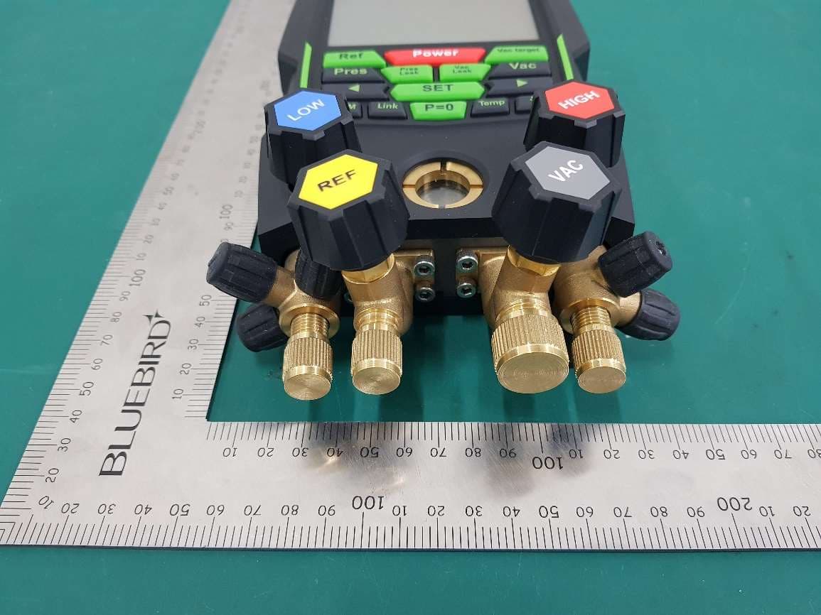
Click to zoom
Application Details
- Equipment Class
- JAB - Part 15 Class B Digital Device
- Date of Grant
- Aug 24, 2020
- Application Purpose
- Original Equipment
- Date of Application
- Aug 24, 2020
- Equipment Note
- Digital Manifold Gauge
- Company
- Sungshin Hasco, Ltd.
- Country
- South Korea
Documents & Files
Document Text
Text extracted from the exhibit documents filed with the FCC. Open a document above to read the original.
Users Manual
FCC Information to User This equipment has been tested and found to comply with the limits for a Class B digital device, pursuant to Part 15 of the FCC Rules. These limits are designed to provide reasonable protection against harmful interference in a residential installation. This equipment generates, uses and can radiate radio frequency energy and, if not installed and used in accordance with the instructions, may cause harmful interference to radio communications. However, there is no guarantee that interference will not occur in a particular installation. If this equipment does cause harmful interference to radio or television reception, which can be determined by turning the equipment off and on, the user is encouraged to try to correct the interference by one of the following measures: Connect the equipment into an outlet on a circuit different from that to which the receiver is con-nected. Consult the dealer or an experienced radio/TV technician for help. Caution Modifications not expressly approved by the party responsible for compliance could void the FCC Compliance Information : This device complies with Part 15 of the FCC Rules. Operation is subject to the following two conditions: (1) This device may not cause harmful interference, and (2) this device must accept any interference received, including interference that may cause undesired operation IMPORTANT NOTE: FCC RF Radiation Exposure Statement: This equipment complies with FCC RF radiation exposure limits set forth for an uncontrolled environment. This equipment should be installed and operated with a minimum distance of 20 centimeters between the radiator and your body. This transmitter must not be co-located or operating in conjunction with any other antenna or transmitter.
Cover Letter(s)
65, Gongdan 7-ro, Jillyang-eup, Gyeongsan-si , Tel: +82-53-853-8826 Gyeongbuk-do, Republic of Korea, 38465 Emai: [email protected] July 31, 2020 Federal Communications Commission 445 12 th Street SW Washington, DC 20554 Subject: Limited Agency Agreement Sungshin Hasco, Ltd. FCC ID: 2AWRJMDM008A To Whom It May Concern: We, Sungshin Hasco, Ltd., hereby authorized Intertek Testing Services to act as our A gent for the purpose of preparing application for FCC ID number 2AWRJMDM008A under all applicable parts of the FCC rules and regulations. The effective date of this limited agency agreement is July 31, 2020. The Limited Agency Agreement expires on October 31, 2020, unless sooner terminated or extended by written notice to Intertek Testing Services and the Federal Communications Commission. This is to advise that we are in full compliance with the Anti-Drug Abuse Act. The applicant is not subject to a denial of federal benefits pursuant to Section 5301 of the Anti-Drug Act of 1988, 21 U.S.C. 862, and no party to the application is subject to a denial of federal benefits pursuant to that section. If you have any questions or comments, please do not hesitate to contact me. Sincerely, [Signature] Kyong Seob, Shin Senior Manager
External Photos
Photographs of EUT Front Rear Right Left Top Bottom
Internal Photos
Photographs of EUT Main Board_Front Main Board_Rear Sub Board_Front Sub Board_Rear Approved Bluetooth Module(BMD-300) Overview
Test Report
Report No.: 200500063SEL-EMC1 Copyright © 2017 Intertek Page 2 of 16 TRF No. FCC15B_A / Version: 24 Apr 2017 SECTION 1 CONTENTS SECTION 2 EMC Results Conclusion (with Justification) ......................................................................................... 3 SECTION 3 Test environment and conditions ...................................................................................................... 3 SECTION 4 EUT Information .............................................................................................................................. 4 SECTION 5 TEST CONFIGURATION, Operation mode and SET-UP .......................................................................... 5 SECTION 6 EMISSION ........................................................................................................................................ 6 SECTION 7 Appendix I ..................................................................................................................................... 12 Photographs of Test Configurations ....................................................................................... 12 SECTION 8 Appendix II .................................................................................................................................... 15 Photographs of EUT .............................................................................................................. 15 Report No.: 200500063SEL-EMC1 Copyright © 2017 Intertek Page 3 of 16 TRF No. FCC15B_A / Version: 24 Apr 2017 SECTION 2 EMC RESULTS CONCLUSION (WITH JUSTIFICATION) We tested the Digital Manifold Gauge, Model: MDM008A, to determine if it was in compliance with the relevant US standard as marked on the test report. We found that the unit met the requirement of FCC Part 15 Subpart B, ICES-003 Issue 6 standards when tested as received. Test Items Applied Standards Results Comply Not Comply N/A See Note Disturbance Voltage FCC Part 15 Subpart B Radiated disturbance (Below 1 GHz) FCC Part 15 Subpart B Radiated disturbance (Above 1 GHz) FCC Part 15 Subpart B Note 1) When determining the test conclusion, the Measurement Uncertainty of test has been considered. Measurement Uncertainty Conducted Emission 150 kHz – 30 MHz U = 3.3 [dB] (Confidence level approximately 95 %, k = 2) Radiated Emissions 9 kHz – 30 MHz U = 4.5 [dB] 30 MHz – 1 000 MHz Horizontal: U = 4.3 [dB] Vertical: U = 4.5 [dB] 1 GHz – 6 GHz Horizontal: U = 5.6 [dB] Vertical: U = 5.4 [dB] 6 GHz – 18 GHz Horizontal: U = 5.8 [dB] Vertical: U = 5.8 [dB] (Confidence level approximately 95 %, k = 2) SECTION 3 TEST ENVIRONMENT AND CONDITIONS Test Environment Test Item Test Site Test date (MM-DD) Temp (°C) Humidity (% R.H.) Pressure (kPa) Disturbance Voltage Shielded Room #2 - - - - Radiated disturbance (Below 1 GHz) 10 m chamber 06-29 23.2 ± 0.5 38.7 ± 0.5 Radiated disturbance (Above 1 GHz) 10 m chamber 06-29 23.3 ± 0.5 38.8 ± 0.5 Report No.: 200500063SEL-EMC1 Copyright © 2017 Intertek Page 4 of 16 TRF No. FCC15B_A / Version: 24 Apr 2017 SECTION 4 EUT INFORMATION Equipment Under Test (EUT): Digital Manifold Gauge Model: MDM008A Variant Model: - Serial No.: - Rated Voltage: DC 6 V Tested Voltage: DC 6 V Maximum clock frequency: 2 480 MHz Variant model information: - Report No.: 200500063SEL-EMC1 Copyright © 2017 Intertek Page 5 of 16 TRF No. FCC15B_A / Version: 24 Apr 2017 SECTION 5 TEST CONFIGURATION, OPERATION MODE AND SET-UP Test Ancillary Equipment Equipment Model No. Serial No. Manufacturer ETC. Digital Manifold Gauge MDM008A - Sungshin Hasco, Ltd EUT Temperature Sensor Clamp X 2 - - Sungshin Hasco, Ltd EUT Smart Phone SM-G981N R3CN5066PCV Samsung Electronics Co., Ltd. - Used cable description Start END CABLE Name I/O Port Name I/O Port Length (m) Shield With Ferrite Digital Manifold Gauge (EUT) K-TYPE X 2 Temperature Sensor Clamp X 2 (EUT) K-TYPE 1.2 Unshielded No - Smart Phone - - - - Test Operation Mode - Operating Mode: A states that connect the smartphone and Bluetooth to run the “Microdam” app to check operation. Test Setup Report No.: 200500063SEL-EMC1 Copyright © 2017 Intertek Page 6 of 16 TRF No. FCC15B_A / Version: 24 Apr 2017 SECTION 6 EMISSION Radiated disturbance test Test Method and Summary Test standard: FCC Part 15 Subpart B Used Test Equipment Control No. Equipment Manufacturer Model No. Serial No. Next Cal. Cal Int. EMC002 EMI Test Receiver R & S ESU26 100590 2021.01.02 1Y EMC025 Biconilog (Type7) ETS-Lindgren 3142E 00203547 2021.02.25 2Y EMC074 AMP R & S SCU-01D 1904843 2021.06.22 1Y Operating Environment Test Voltage: DC 6 V Test Setup and Procedure The EUT along with its peripherals were placed on a non-conducted table with a height of 0.8 m in height table above the reference ground plane. Rotate the EUT from 0° to 360° and position the receiving antenna at heights from 1 m to 4 m above the reference ground plane continuously to determine associated with higher emission levels and record them. The measurement was made in both the vertical and horizontal polarization, and the maximum value is presented in the report. For measurements above 1 GHz, place the measurement antenna away from each area of the EUT determined to be a source of emissions at the specified measurement distance, while keeping the measurement antenna aimed at the source of emissions at each frequency of significant emissions, with polarization oriented for maximum response. The measurement antenna may have to be higher or lower than the EUT, depending on the radiation pattern of the emission and staying aimed at the emission source for receiving the maximum signal. The final measurement antenna elevation shall be that which maximizes the emissions. Report No.: 200500063SEL-EMC1 Copyright © 2017 Intertek Page 7 of 16 TRF No. FCC15B_A / Version: 24 Apr 2017 Limits - The test frequency range of Radiated Disturbance measurements are listed below. Highest frequency generated or used in the device or on which the device operates or tunes (M…
Text truncated - open the document above for the full version.
Test Setup Photos
Test Setup Photo Photographs of Test Configurations N/A Disturbance Voltage Test N/A Disturbance Voltage Test Radiated disturbance (30 MHz ~ 1 GHz) Radiated disturbance (30 MHz ~ 1 GHz) Radiated disturbance (Above 1 GHz) Radiated disturbance (Above 1 GHz)
Contact Information
Applicant
Kyong Seob Shin(head of department)
Technical Contact
Intertek ETL SEMKO Korea Ltd.Bran Ko
[email protected]+82 31 8069 3761
Intertek building, 3, Gongdan-ro 160beon-gil, Gunp · Gyeonggi-do · South Korea
Non-Technical Contact
Intertek ETL SEMKO Korea Ltd.Bran Ko
[email protected]+82 31 8069 3761
Test Firm
Intertek ETL SEMKO Korea Ltd.Ko Bran
Technical Specifications
| # | Rule Parts | Frequency Range | Power Output |
|---|---|---|---|
| 1 | 15B | - | - |
Other Applications from Sungshin Hasco, Ltd.
2AWRJ-MDM009A
May 18, 2023Digital Manifold Gauge
Equipment Class
DTS - Digital Transmission System